ML Accessories Knightsbridge DC010 Manual

INSTALLATION & MAINTENANCE MANUAL
DC010 / DC012 / DC013 / DC014 / DC015 / DC016
DCBPB / DCBPW / DCRB / DCRW /

These instructions should be read carefully and retained after installation by the
end user for future reference and maintenance.
These instructions should be used to aid installation of the following products:
DC010 / DC012 / DC013 / DC014 / DC015 / DC016 / DCBPB / DCBPW / DCRB /
DCRW
GENERAL INSTRUCTIONS
SAFETY
• Avoid positioning the bell push on metal door frames as this may affect the signal
• Avoid positioning above or near heat sources such as radiators, or in damp areas such as
kitchens and bathrooms
• Avoid mounting PIR sensor near a heat source or area where there is frequent movement
to avoid nuisance triggering
• Please note the IP (Ingress Protection) rating of the bell push when deciding the location
for installation
• The bell push is IP55 rated
• The PIR sensor and receivers are IP20 rated for internal use only
LAYOUT
34.2mm
88mm
23mm
26mm
70.5mm
81mm
81.5mm 56mm
26.2mm
81mm
81.5mm 81.5mm
81mm
81.5mm
81mm
81.5mm
Push Button P+
Door Chime B6 Door Chime B9 Door Chime B12 Door Chime B15 UK Plug Door Chime
Door Chime B5 Battery Powered Door Chime
52.16mm
112.4mm 42mm
Indoor PIR HP04D
Outdoor PIR FS03D
105mm
82mm 62mm
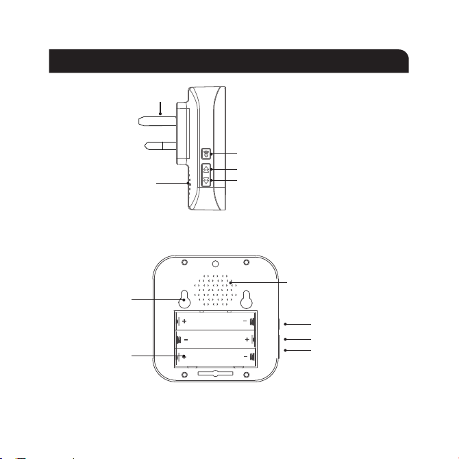
AC plug
Speaker
Volume control button
Previous melody button
Next melody button
Battery operated receiver
Plug-in receiver
Volume control button
Previous melody button
Next melody button
Speaker
Fixing holes
Battery
compartment
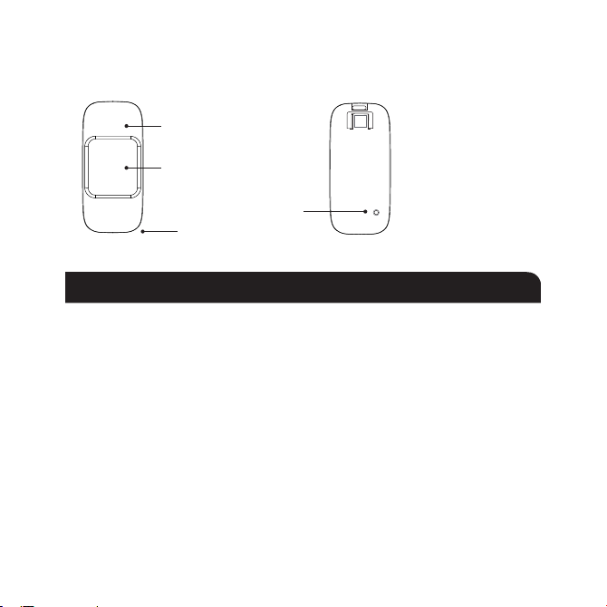
LED indicator
Motion detector
Front cover screw
PIR motion sensor
34.2mm
88mm
23mm
26mm
70.5mm
81mm
81.5mm 56mm
26.2mm
81mm
81.5mm 81.5mm
81mm
81.5mm
81mm
81.5mm
Push Button P+
Door Chime B6 Door Chime B9 Door Chime B12 Door Chime B15 UK Plug Door Chime
Door Chime B5 Battery Powered Door Chime
52.16mm
112.4mm 42mm
Indoor PIR HP04D
Outdoor PIR FS03D
105mm
82mm 62mm
Test button
BATTERY INSTALLATION
Bell push
• Using the screwdriver provided, insert into the hole between the button cover and
base of the bell push and tilt downwards to open the cover
• Insert the 12V 23A Alkaline battery (included)
• Replace cover
PIR sensor
• Unfasten the screw from the top of the sensor, and remove the cover
• Insert 2 x AA batteries (not included)
• Replace cover

Receiver
• Press the two holding clips on the battery cover on the rear of the receiver and pull open
• Insert 3 x AAA batteries (not included)
• Replace cover
Mounting bell push
• When using screws and wall plugs provided to attach to a surface, open the bell push
and pierce the two fixing holes on the baseplate of the bell push
• Mark the location of the fixing holes and drill ensuring not to infringe with any gas/water
pipes or electrical cables
• Screw the baseplate to the wall and re-attach the cover
• To attach using the double-sided adhesive pad, ensure the surface is clean and dry
• Peel back one side of the pad and attach to the rear of the bell push then peel back the
rear of the pad and attach to the desired surface
Mounting PIR sensor
• Using the bracket as a template, mark the location of the fixing holes and drill ensuring
not to infringe with any gas/water pipes or electrical cables
• Screw the bracket to the wall using the screws and wall plugs provided
• Attach the ball bracket to the rear of the sensor, then attach to the bracket mounted to
the surface
• Adjust the bracket to change the detection distance and angle of the sensor
• It is recommended to mount the detector 2.0~2.2m from the ground to cover maxima
detection area

Mounting battery operated receiver
• Measure the distance between the fixing centres on the rear of the receiver and mark the
location for, and drill the fixing holes ensuring not to infringe with any gas/water pipes or
electrical cables
• Using the screws and wall plugs provided insert the screws leaving the head of the screw
exposed
• Attach the receiver to the two exposed screw heads
Pairing
• Select the desired melody using the next / previous melody buttons
• Hold and press the volume control button for about 5s until a “ding-dong” is heard and
the LED indicator starts flashing: you are now in pairing mode
• Press the bell push or activate the PIR sensor within 5 seconds
• Press the bell push or activate the PIR, the selected melody should sound to confirm
pairing is successful - if not repeat the pairing process
• Extra receivers and bell pushes can be added by following the same pairing procedure

GENERAL
These products should be recycled in the correct manner when they reach the end of their
life. Check local authorities for where facilities exist.
Clean with a soft dry cloth only, do not use aggressive cleaning products or solvents which
may damage the product.
Remove batteries if the product is to be unused for a long period
WARRANTY
These products have a warranty of 1 year from date of purchase. Failure to install this
product in accordance with the current edition of the IEE Wiring Regulations (BS7671),
improper use, or removal of the batch code will invalidate the warranty. If this product
should fail within its warranty period, it should be returned to the place of purchase for a
free of charge replacement. ML Accessories does not accept responsibility for any installation
costs associated with the replacement product. Your statutory rights are not affected. ML
Accessories reserve the right to alter product specification without prior notice.
AKJUL22_V2
137
SUPPLIED BY:
(UK) MANUFACTURER
ML ACCESSORIES LTD, UNIT E CHILTERN PARK, BOSCOMBE ROAD, DUNSTABLE LU5 4LT,
WWW.MLACCESSORIES.CO.UK
(EU) AUTHORISED REPRESENTATIVE
SLV LIGHTING GROUP, DAIMLERSTRASSE 21-23,
52531 ÜBACH-PALENBERG, GERMANY
EMAIL: EPREL@GROUP.SLV.COM

Manufacturers Declaration of Conformity
For ML Accessories (Knightsbridge)
Electrical products in accordance with CE marking
ML Accessories Ltd. Declare that all products have been designed, manufactured, and tested in
accordance with the requirements of the relevant legislation
CE marking legislation
In Accordance with the following Directives:
2014/35/EU Low Voltage Directive
2014/30/EU EMC Directive
2014/53/EU Radio Equipment Directive
Including Legislation
1907/2006 REACH
2015/863 RoHS
2021/341 ERP
Safety Standards
Full individual declarations and specific safety standards applicable to relevant product series can be found on
our website www.mlaccessories.co.uk
We hereby declare that the equipment named above has been designed to comply with the relevant
sections of the above referenced specifications. The product complies with all essential requirements of
the directives.
Scott Brewer Catherine Connolly
Technical Manager CEO
ML Accessories Ltd. Unit E Chiltern Park, Boscombe Road, Dunstable. Bedfordshire, LU5 4LT
This declaration becomes invalid if technical or operational modifications are introduced without ML Accessories Ltd. written consent.

Manufacturers Declaration of Conformity
For ML Accessories (Knightsbridge)
Electrical products in accordance with UKCA marking
ML Accessories Ltd. declare that all products have been designed, manufactured, and tested in
accordance with the requirements of the relevant legislation
UKCA marking legislation
UK SI 2016 No. 1091 Electro Magnetic Compatibility Regulations 2016
UK SI 2016 No. 1101 The Electrical Equipment (Safety) Regulations 2016
UK SI 2012 No. 3032 Restriction of the use of Certain Hazardous Substances in Electrical and
Electronic Equipment Regulations 2012
UK SI 2017 No. 1206 Radio Equipment regulations 2017
UK SI 2021 No. 1095 The Ecodesign for Energy-Related Products and Energy
Information (Lighting Products) Regulations 2021
Included Legislation
UK SI 2008 No. 2852 UK REACH
UK SI 2013 No. 3113 WEEE
Safety Standards
Full individual declarations and specific safety standards applicable to relevant product series can be found on
our website www.mlaccessories.co.uk
We hereby declare that the equipment named above has been designed to comply with the relevant
sections of the above referenced specifications. The products comply with all essential requirements of
the directives.
Scott Brewer Catherine Connolly
Head of Technical CEO
ML Accessories Ltd. Unit E Chiltern Park, Boscombe Road, Dunstable. Bedfordshire, LU5 4LT
This declaration becomes invalid if technical or operational modifications are introduced without ML Accessories Ltd. written consent.
This manual suits for next models
9
Table of contents
Popular Receiver manuals by other brands


Pioneer
Pioneer MVH-S329BT owner's manual

PCB Piezotronics
PCB Piezotronics 010F05 Installation and operating manual

Sky Master
Sky Master DXS 23 operating instructions

A-Neuvideo
A-Neuvideo ANI-HDR-200 instruction manual

Digital Stream
Digital Stream DEXUS DST-HD1100E User instructions

Securitytronix
Securitytronix ST-CCTV-VBAC16 installation manual