MMF KSI 80VC-20 User manual

kManfred Weber
Metra Mess- und Frequenztechnik in Radebeul
D-01445 Radebeul Meissner Str. 58 Internet: www.MMF.de
P one +49-351-836 2191 Fax +49-351-836 2940 Email: Info@MMF.de
Instruction Manual
Vibration Velocity Sensor / Transmitter KSI 8 VC / KSI 82VB
1.Purpose
The vibration velocity transducers KSI 80VC / KSI 82VB are intended for continuous monitoring of
rotating machinery for trending or shutdo n based on standard ISO 10816. The rugged, double shielded
and electrically insulated design allo s applications under harsh environmental conditions. The sensors
provide a filtered and rectified output signal hich is compatible ith 4-20 mA current loop standard.
Hence it can be directly connected to standard equipment such as PLCs, panel meters or current relays.
Additional equipment for sensor supply and signal conditioning is not necessary.
The frequency ranges are 1.5 to 1000 Hz ith model KSI 80VC and 10 to 1000 Hz ith model
KSI 82VB.
Both types are available in t o versions each ith 20 mm/s nominal range (models KSI 80VC-20 /
KSI 82VB-20) and ith 40 mm/s nominal range (models KSI 80VC-40 / KSI 82VB-40).
The sensors require no calibration.
2.Function
In spite of their small dimensions models KSI 80VC and KSI 82VB feature a complex signal conditioning
circuit. The main components are sho n in Figure 1.
`
P ie z o
In t e g r a t.
T P 1 k H z R M S 4 -2 0 m A
H P 1 ,5 /1 0 H z
RL
US
V
K S I 8 x V B
4
3
2
Figure 1: Block diagram and external connections
The sensing element is a precise piezoceramic ring-shear system. It measures vibration acceleration. The
acceleration signal is amplified follo ed by an integrator for vibration velocity. The signal is high pass
filtered at 1.5 Hz (KSI 80VC) or 10 Hz (KSI 82VB) and lo pass filtered at 1000 Hz ith 2 pole filters.
The frequency band of model KSI 82VB from 10 to 1000 Hz is usually sufficient for vibrations caused by
unbalance. It is also recommended in standard ISO 10816-1. In some applications ith slo running
machinery it may be necessary to measure from 1.5 to 1000 Hz ith model KSI 82VB.
A true RMS rectifier and a 4-20 mA current loop converter make the signal ready for long distance
transmission.
With the KSI 80VC / KSI 82VB no separate po er supply is required. The sensor is loop po ered.

3.Mounting and Connection
Mounting
An important condition for accurate vibration measurement is the selection of suitable measuring points on
the structure. For this purpose it can be helpful to consult a specialist ith experience in machine
monitoring.
In general, it is advisable to measure vibration as near as possible to its source. This ill minimize
distortion of the measured signal by transmitting mechanical components. Suitable measuring points are
rigid components, for instance the housing of bearings or gearboxes. Not recommended for vibration
measurement are light eight, flexible and soft components.
The standard ISO 10816-1 gives some recommendations for suitable measuring points.
The KSI 80VC / KSI 82VB can be mounted using an M8 stud bolt hich is scre ed into the
tapped hole of the sensor base. The sensor can also be mounted by a magnetic base Model
208 (M8) or Model 008 (M5) ith the adapter Model 044.
A perfect vibration transmission from the measuring object to the sensor is crucial for precise
results. Rough, scratched or too small measuring points may cause errors. Cast or varnish
surfaces are unsuited.
It is recommended to prepare the measuring point by epoxy cementing a polished steel plate
Model 229 ith M8 stud. A thin layer of silicon grease ill also improve vibration
transmission.
Connection
!
Please read the follow ng carefully. Connect on fa lures may cause malfunct on or even
damage to the sensor.
Models KSI 80VC / KSI 82VB are connected via a aterproof four pin M12 connector model Binder 713.
The follo ing optional connection accessories are available from Metra:
Model 080G/W: Straight (G) or angled (W) plug of Binder 713 series ith scre terminals for simple
connection to existing cables, protection grade IP67
Model 084G/W: 5 m shielded cable ith 4 ires, ith straight (G) or angled (W) plug Binder 713 and
pigtail ends; protection grade IP67
The pin assignment is as follo s:
Vie at socket Pin Assignment
12
3
4
1:
2:
3:
4:
No connection
+ current loop
- current loop
case
!
If the test object has no connect on to earth potent al, connect p n 4 to earth or another
reference potent al to ensure proper sh eld ng.
Make sure that the cable is not routed alongside AC po er lines. It must cross AC po er lines at right
angles. The cable should also be routed a ay from potential sources of EMI, e.g. motors, frequency
converters, generators, transformers or radio transmitters.
The sensor cable should be anchored to reduce stress at the connector. When securing the cable, leave
enough slack to allo free movement of the sensor.
The sensor output is connected via pin 2 and 3. Any t o conductor cable can be used. At long distances
and high EMI, ho ever, it is recommended to use shielded t o conductor cables. The cable shield should
be tied to earth potential only at one side to avoid ground loops.
The 4-20 mA loop is po ered from a filtered DC voltage source US as sho n in Figure 1. The load resistor
RL is in series ith the sensor. The load resistor RL and the voltage source US are often part of the read-out
or processing equipment. The KSI 80VC / KSI 82VB requires for normal operation a minimum voltage
KSI 80V
KSI 82V
M8
Epoxy

drop of 12 VDC across its terminals. Figure 2 sho s the permissible limits for the load resistor RL against
the loop supply voltage US.
15
18
21
24
27
0
100
200
300
400
500
Rmax(25mA)
Rmin(25°C)
12
30
Us / V
Rmin(85°C)
Figure 2: Permissible range for the load resistor against loop supply voltage
!
Please make sure that the loop supply voltage US s free of r pple. To suppress nterference, t
s recommended to connect the negat ve term nal of the voltage source to earth potent al.
A commercially available DC/DC converter (24 V : 24 V) may be used to regenerate a noisy 24 V supply.
The 4-20 mA output is protected against reverse iring.
4.What to Do if the Sensor Does Not Work
Problem: The output is above 4 mA although the sensor is not exposed to vibration or the output is rong.
Check the quality of your loop supply. If there is AC ripple, use a separate 24 VDC supply or
regenerate the supply voltage by a DC/DC converter.
In case of strong AC components at machine ground, particularly in the presence of frequency
converters, interference ithin the sensor circuit may occur. This problem can be solved by isolated
mounting using the isolating flange Model 206.
Check the voltage drop at the loop terminals of the sensor. If it is less than 12 VDC, the sensor circuit
may oscillate or the output may be clipped. If applicable, increase the loop supply voltage or lo er the
load resistance.
If the problem should persist in spite of these measures, please contact the manufacturer.
5.Optionally Available Accessories
080G/W: Plug Binder 713 straight (G) or angled (W) ith scre terminals
084G/W: 5 m cable ith plug Binder 713 straight (G) or angled (W) and pigtail ends
043: Stud bolt M8 x 16
229: Adhesive mounting pad M8
208: Magnetic base ith M8 stud
M12DIS: LCD module for vibration velocity display, 4-20 mA input, ith backlight

6.Technical Data
KSI 80VC-20 KSI 80VC-40 KSI 82VB-20 KSI 82VB-40
Output: RMS of vibration velocity, 4-20 mA
Measuring range (vMIN .. vMAX): 0.2 .. 25 mm/s 0.4 .. 50 mm/s 0.2 .. 25 mm/s 0.4 .. 50 mm/s
Nominal value at 20 mA: 20 mm/s 40 mm/s 20 mm/s 40 mm/s
Sensitivity: 0,8 mA/mms-1 0,4 mA/mms-1 0,8 mA/mms-1 0,4 mA/mms-1
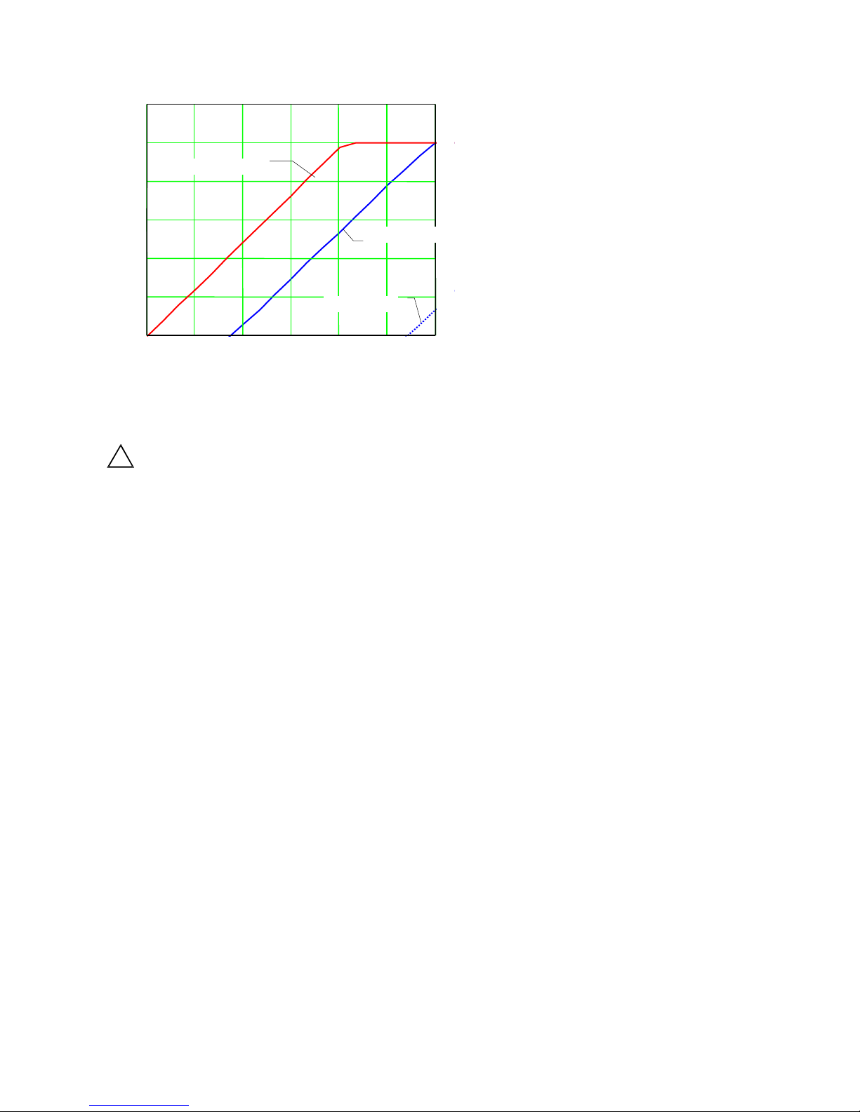
Frequency range (-3 dB): 1.5 .. 1000 Hz 10 .. 1000 Hz
Frequency range (-10 %): 3 .. 650 Hz 20 .. 650 Hz
Non-linearity (vMIN .. vMAX, 25 °C): ± 3 %
Residual noise: ± 0.01 mm/s ± 0.005 mm/s
Output ripple: f > 5 Hz
f = 3 Hz
f = 1,5 Hz
< 1 %
2 %
6 %
Settling time to 1 % tolerance: 10 s 2 s
Destruction shock limit: ± 4000 g
Transverse sensitivity: < 5 %
Loop supply voltage: 12 .. 30 V
Maximum linear output current: 25 mA
Maximum output current at overload: < 35 mA
Operating temperature range: - 40 .. 85 °C
Temperature coefficient of sensitivity: ± 0.05 %/K
Temperature drift of zero point: + 0.9 µms-1/K
Protection grade: IP67
Case material: Stainless steel
Weight ithout cable: 66 g
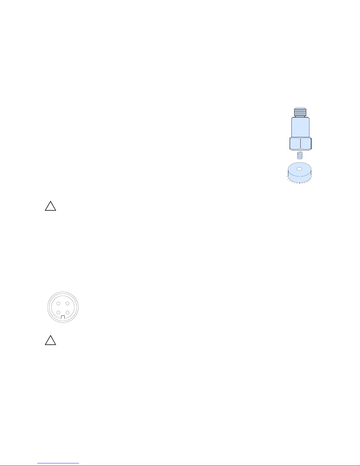
Mounting: M8 tapped hole in base
Warranty
Metra arrants for a period of
24 months
That its products ill free from defects in material and
orkmanship and shall conform to the specifications
current at the time of shipment. The arranty period
starts ith the date of invoice.
The invoice must be presented as proof of purchase.
The arranty period ends after 24 months.
Repairs do not extend the arranty period.
The limited arranty only covers defects hich arise
as a result of normal use according to the instruction
manual.
Metra's obligations under this arranty do not apply in
cases of improper or inadequate maintenance or
modification and operation outside the product's
specifications
Shipment to Metra ill be paid by the customer.
The repaired or replaced product ill be sent back to
the customer at Metra's expense.
Declaration of Conformity
According to EMC Directive 2014/30/EC
Product: Vibration Velocity Transmitters
Type: KSI80VC / KSI82VB
It is hereby certified that the above mentioned
product complies ith the demands pursuant to
the follo ing standards:
DIN EN 61326-1: 2013
DIN EN 61010-1: 2011
DIN 45669-1: 2010
The producer is responsible for this declaration
Metra Mess- und Frequenztechnik
in Radebeul e.K.
Meißner Str. 58, D-01445 Radebeul
declared by
Michael Weber
Radebeul, 3rd March 2016
May/16
This manual suits for next models
3
Table of contents