Mo-vis Twister Pro User manual

moving forward together
Twister Pro
Twister Pro (D36) 1500 mm Black/Red/Green
(P030-11/12/13) - Twister Pro (D36) 300 mm Black/Red/
Green (P030-21/22/23)
Installation manual
Edition 1, August 2021

Contents
Contents About this manual .............................................................................. 3
Installation manual ................................................................... 3
mo-vis bv ................................................................................... 3
Important information ........................................................................ 4
Warranty ............................................................................................ 5
Repair and replacement ............................................................ 5
Amendments ............................................................................. 5
Disclaimer and limitations of remedies .................................... 6
Voiding of warranties ................................................................ 6
Technical support ................................................................................ 7
Warning labels .................................................................................... 8
Limited liability ................................................................................... 9
Operation ......................................................................................... 10
Normally open switch ............................................................. 10
Safety button .......................................................................... 10
1

Installation ....................................................................................... 12
Installation Plan ...................................................................... 12
Installation .............................................................................. 13
Adjusting the dip switch .......................................................... 14
External configuration ....................................................................... 16
Curtiss-Wright R-net parameters ............................................ 16
Dynamic Controls parameters ................................................. 17
Maintenance .................................................................................... 19
Monthly inspection ................................................................. 19
Technical data ................................................................................... 20
Product description & code .................................................... 20
Specifications .......................................................................... 20
2

About this manual
Installation manual
This manual contains useful and important information about your device.
Please read it carefully before use and store safely for future reference.
Our team will be happy to answer your questions.
mo-vis bv
Biebuyckstraat 15D . 9850 Deinze . Belgium
3
Twister Pro Installation manual 3

Important information
CAUTION: Incorrect use or installation may lead to risk of injury to
the user and damage to the wheelchair or other property. In order to
reduce these risks, you should carefully read this installation manual,
paying particular attention to the safety instructions and warning texts.
NOTICE: Only install this product on a wheelchair where the wheelchair
manufacturer allows the installation of third party parts.
4
4 Twister Pro Installation manual

Warranty
mo-vis bv warrants the product to be free from defects in material and
workmanship for a period of 2 years under proper use, care and service. The
dealer should never keep mo-vis products in stock for a period more than 6
months prior to delivery to the end-user. mo-vis' warranty will never exceed a
period of 2 years and 6 months after shipment.
All warranties do not extend beyond the initial purchaser from an authorized
mo-vis dealer or mo-vis itself.
Repair and replacement
For warranty service, contact your dealer (or us if bought directly). In the
event of a defect in material or workmanship, the dealer or customer must
obtain a Return Merchandise Authorization (RMA) number from us. The
product must be shipped to a service centre designated by mo-vis. mo-vis will
repair or, at mo-vis’ option, replace any product covered by the warranty.
Amendments
No person is authorized to alter, extend or waive the warranties of mo-vis.
5
Twister Pro Installation manual 5

Disclaimer and limitations of remedies
The express warranties set forth in this agreement are in lieu of all other
warranties of merchantability or fitness of purpose. In no event shall mo-
vis be liable for any direct, indirect, incidental or consequential damages
resulting from any defect in this product.
Warranty of parts subject to “normal wear and tear” (e.g. joystick handles,
pads, …) are not covered in the warranty except as it applies to defects in
material or construction.
Voiding of warranties
The foregoing warranties are contingent upon the proper installation, use,
maintenance and care of the product. The warranty will be void if the product
has been installed or used improperly, or if it has been repaired or any part
replaced by persons other than mo-vis or an authorized dealer. This product
is considered as a non-serviceable part.
The addition of equipment or features that are not manufactured or
recommended by mo-vis could affect the intended function of the mo-vis
product and may invalidate the warranty.
6
6 Twister Pro Installation manual


Warning labels
Please read this manual, the safety instructions and warning texts carefully,
in order to reduce the risks associated to the device. Our products are safe
under normal and reasonably foreseeable operating conditions.
NOTE: This symbol indicates general notes and information.
CAUTION: This symbol indicates caution for a hazardous situation that,
if not avoided, could result in minor or moderate injury.
WARNING: This symbol indicates a warning for a hazardous situation
that, if not avoided, could result in death or serious injury.
8
8 Twister Pro Installation manual

Limited liability
mo-vis accepts no liability for personal injury or damage to property
that may arise from the failure of the user or other persons to follow the
recommendations, warnings and instructions in this manual.
CAUTION: Carry out only the service and maintenance activities
specified in this manual, as long as you comply with the demands
stated in this manual for a specific action. In case of doubt, contact mo-
vis.
WARNING: The device should always be tested without any person
sitting in the wheelchair after every alteration of the physical
installation or adjustment of the parameters.
9
Twister Pro Installation manual 9

Operation
Normally open switch
The Twister Pro can be used as a standard normally open switch: it will
activate when pressed down. Simply plug in the Twister Pro into a 3.5 mm
female jack on a switch-adapted device, joystick or computer.
To activate the Twister Pro, simply press anywhere on the top of the
activation surface. You will feel and hear an audible 'click'.
NOTE: The Twister Pro is by default delivered and set as a normally
open switch.
Safety button
The Twister Pro can also be configured using a dip switch on the bottom, so
that it functions as a safety button.
10
10 Twister Pro Installation manual
NOTE: The safety feature can detect if the switch is disconnected or
if the cable is in short circuit. This provides additional safety to the
device!
NOTE: This feature allows to be compliant with the ISO 7176:14-2008
§7.2.3.4 Leakage Current Test.
NOTE: This functionality is only possible when the host system
supports this.
11
Twister Pro Installation manual 11

Installation
CAUTION: Before you start with the installation:
• Please check the packaging and verify that all items are included.
• Make sure that you have all the necessary documentation and
knowledge to install this device.
• Check the condition of the device.
Installation Plan
Set up an installation plan before beginning the installation. Based on the
users' needs and capabilities, this plan should take into account:
• Where which part of the device should be placed.
• How the device will be operated.
• A robust and reliable positioning. Hard or sudden movements of the
wheelchair may not disorganize the installation.
WARNING: Protect the device against bumps. Mind damaging the
unit and wiring. Make sure that cabling is mounted in such a way that
excessive wear and tear is avoided.
12
12 Twister Pro Installation manual

WARNING: Make sure that loose parts of the cable are out of reach to
avoid strangulation or other injuries.
CAUTION: Long periods of repetitive motion using the product may be
associated with nerve, tendon or muscle injury in your hands, wrists,
arms, shoulders, neck or back. See a qualified health professional for
pain, numbness, weakness, swelling, burning, cramping or stiffness.
CAUTION: Do not pull or wrap the cable around the device.
Installation
1 Define the position of the device. Make sure that it is easily accessible to
the user.
2 The device should be mounted on a flat surface. It should be mounted
securely with consideration for minimal risk of jamming or blocking
(access to) the device.
NOTE: Use the delivered screws for surfaces with a thickness of up
to 2 mm. If you use a thicker surface, be aware that the depth of
the insert is 3 mm max.
3 The connector jack should stay clean and needs to be inserted
completely into the device.
13
Twister Pro Installation manual 13
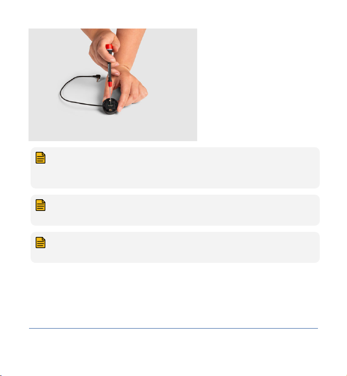
Adjusting the dip switch
Adjust the dip switch by following these steps:
1 Disconnect the switch.
2 Remove the rubber insert on the bottom of the device.
3 Configure the dip switch by using a small screwdriver (see positions
below).
4 Reapply the rubber insert.
CAUTION: If the rubber insert is not fitted correctly or even at all,
this can compromise the waterproofness of the device.
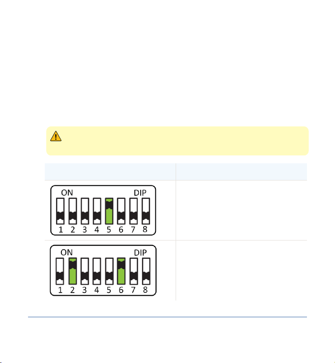
POSITION FUNCTIONALITY
Default position: compatible with
default systems which require a
normally open connection.
R-net resistor values: Compatible
with Curtiss-Wright specifications
for the CJSM II and Omni II.
14
14 Twister Pro Installation manual


External configuration
In order for the safety switch functionality to work, some parameters of the
wheelchair electronics need to be set correctly:
•Curtiss-Wright R-net parameters on page 16
•Dynamic Controls parameters on page 17
Curtiss-Wright R-net parameters
For more information, please refer to the Curtiss-Wright manual SK77981-14
| R-net Technical Manual | Chapter 7 - Controls.
External Profile Jack Detect
Controls > Global > External Profile Jack Detect
VALUE DESCRIPTION
Off The Twister Pro will function as a normally open switch.
On The Twister Pro will be able to detect both open-
and short-circuits in the wiring. If such conditions are
detected, the function associated with the External Pro-
file Switch Jack will be disabled and a warning will be
displayed on the screen.
16
16 Twister Pro Installation manual

NOTE: Controls > External Profile Jack Function > Actuator Switches
should be set to No for the button to be able to detect open- and short
circuits.
External On/Off Jack Detect
Controls > Global > External On/Off Jack Detect
VALUE DESCRIPTION
Off The Twister Pro will function as a normally open switch.
On The Twister Pro will be able to detect both open- and
short-circuits in the switch itself or its wiring. If such
conditions are detected, a trip will occur.
Limp The Twister Pro will be able to detect both open- and
short-circuits in the switch itself or its wiring. If such
conditions are detected, the system will still allow Drive
but at a reduced speed and will issue a visual and audi-
tive warning.
Dynamic Controls parameters
For more information, please refer to the GBK54036 LiNX Systems Installation
Manual.
17
Twister Pro Installation manual 17

LiNX control inputs recognize a number of distinct resistor bands. For each
band, a different action can be selected (e.g. driving, actuator motions,
profile and function navigation and lighting).
Control inputs can be configured to monitor for errors, such as short circuit,
invalid open circuit, missing or unreliable states.
mo-vis has chosen resistor bands 1 and 10: the Twister Pro can perform
monitoring function in these bands, when the dip switch is set to the right
values (see Installation on page 12 ).
NOTE: This setting is only accessible with a LiNX Access Key DLX-
HKEY-02.
Chair Set-up > Modules > Rem XXX > Left/Right Jack Socket Tip > Advanced
> Monitored
VALUE DESCRIPTION
Off The Twister Pro will function as a normally open switch.
On The Twister Pro will be able to detect both open- and
short-circuits in the wiring. The error is indicated to the
user and logged in the system.
18
18 Twister Pro Installation manual

Maintenance
The device is maintenance-free. Under regular circumstances of use, the
device and different parts do not require additional maintenance. Please
refer to the User Manual of the device for cleaning instructions.
WARNING: As dust and dirt could lead to reduced functionality, all
parts of the device should be cleaned on a regular basis (monthly) or
whenever needed.
Monthly inspection
Monthly, or whenever needed, check whether:
• All bolts and screws are still firmly tightened.
• There is no damage to any wiring.
• There is no excessive wear to any of the parts.
19
Twister Pro Installation manual 19
Other manuals for Twister Pro
1
This manual suits for next models
6
Table of contents
Other Mo-vis Switch manuals


Popular Switch manuals by other brands


CyberData
CyberData 10807 Operation guide

D-Link
D-Link Web Smart DES-1210-28P Specifications

TRU Components
TRU Components 2144015 operating instructions

Potter
Potter VSR-F instructions

NETGEAR
NETGEAR M4300 Intelligent Edge Series Hardware installation guide

Siemens
Siemens SIRIUS 3SE2903-1AE20 Original operating instructions


