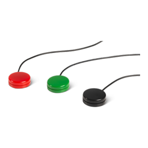
Mo-vis P014-40 Guide

User & Installation Manual
EN
Multi Switch
Control multiple outputs with one input
Multi Switch (P014-40)
Multi Switch Proximity sensors (P014-41)

2
Contact & Product
mo-Vis bvba
Biebuyckstraat 15 D
9850 Nevele - Belgium
Website: www.mo-vis.com
E-mail: contact@mo-vis.com
Telephone: +32 9 335 28 60
Hand Warmer User & Installation manual
Produced and published by mo-Vis bvba, Belgium
Edition October 2016
Manual item: D-P014-40-70-00

Multi Switch 3
Contents
Contact & Product-----------------------------------------------------------------------2
mo-Vis bvba------------------------------------------------------------------------2
Hand Warmer User & Installation manual ---------------------------------2
Contents -----------------------------------------------------------------------------------3
Important information about this Manual ----------------------------------------5
Support, scrapping and spare parts -------------------------------------------------7
Warranty-----------------------------------------------------------------------------------8
Safety precautions -------------------------------------------------------------------- 11
Design and function of the Multi Switch----------------------------------------- 15
Parts and accessories---------------------------------------------------------- 17
Technical description of the Multi Switch -------------------------------- 20
Technical description of the Multi Switch Proximity sensors-------- 22
mo-Vis Configurator software----------------------------------------------- 24
Installation instructions -------------------------------------------------------------- 26
Preparations --------------------------------------------------------------------- 27
Installation of the Multi Switch --------------------------------------------- 28
Usage ------------------------------------------------------------------------------------- 30
First time use -------------------------------------------------------------------- 31
User adjustments--------------------------------------------------------------- 32
Operation modes ---------------------------------------------------------------------- 33
Select Modes -------------------------------------------------------------------- 33
Momentary/Timed or Switched -------------------------------------------- 35

4
Lock Mode ----------------------------------------------------------------------- 35
Calibration Mode --------------------------------------------------------------- 36
Troubleshooting ----------------------------------------------------------------------- 37
Error codes----------------------------------------------------------------------- 39
Maintenance---------------------------------------------------------------------------- 42
Parameter settings -------------------------------------------------------------------- 43
Technical data -------------------------------------------------------------------------- 48

Multi Switch 5
Important information about this Manual
Congratulations for choosing a mo-Vis product! If you would like to
learn more about mo-Vis and its products, we invite you to visit our
website: www.mo-vis.com.
Before you install or begin using this product, it is important that
you read and understand the content of these installation and
operating instructions, the safety instructions in particular.
The installation instructions will guide you as an installer through
the options and possibilities with the mo-Vis product. The mo-Vis
product should be adjusted with the mo-Vis Configurator software.
The operating instructions are primarily intended to acquaint you
with the functions and characteristics of the mo-Vis product and
how you can use it in the best manner possible. They also contain
important safety and maintenance information, as well as describe
possible problems that can arise during use.
Always keep the operating instructions handy in connection with
your device, since the need for important information can arise
concerning its use, safety and maintenance.
All information, pictures, illustrations and specifications are based
on the product information that was available at the time of
printing. Pictures and illustrations shown in these instructions are
representative examples and are not intended to be exact
depictions of the various parts of the product.

6
We reserve the right to make changes to the product without prior
notice.
Ordering documentation
You can download additional copies of this User & Installation
manual on the mo-Vis website: www.mo-vis.com.

Multi Switch 7
Support, scrapping and spare parts
Technical support
In case of technical problems, we advise you to contact your dealer.
If the dealer is not available, or unknown, please contact mo-Vis
Always state the device serial number when contacting mo-Vis. This
ensures you are provided with the correct information.
Spare parts and accessories
Spare parts and accessories must be ordered by the dealer at mo-
Vis bvba.
Scrapping & recycling
For scrapping, adhere to your local waste legislation.
Dispose of obsolete electronic parts responsibly in accordance with
local recycling regulations.

8
Warranty
mo-Vis bvba warrants the Multi Switch and Multi Switch Proximity
Set to be free from defects in material and workmanship for a
period of 2 years under proper use, care and service.
All warranties only cover parts and do not extend beyond the initial
purchaser from an authorized mo-Vis dealer.
Start of the warranty period
Each warranty shall begin on the date the product is first delivered
to the customer.
Repair and replacement
For warranty service, we advise you to contact the dealer from
whom the product was purchased. In the event of a defect in
material or workmanship, the dealer must obtain a return
authorisation (RA) number from mo-Vis and the product must be
shipped to a service centre designated by mo-Vis. mo-Vis will repair
or, at mo-Vis’ option, replace any product covered by the warranty.
Disclaimer and Limitations of Remedies
The express warranties set forth in this agreement are in lieu of all
other warranties of merchantability or fitness of purpose. In no
event shall mo-Vis be liable for any direct, indirect, incidental or
consequential damages resulting from any defect in this product.

Multi Switch 9
Warranty of parts subject to “normal wear and tear” (e.g. pads,
joystick balls, batteries …) are not covered in the warranty except as
it applies to defects in material or construction.
Amendments
No person is authorised to alter, extend or waive the warranties of
mo-Vis.
Voiding of warranties
The foregoing warranties are contingent upon the proper
installation, use, maintenance and care of the product. The
warranty will be void if the product has been installed or used
improperly, or if it has been repaired or any part replaced by
persons other than mo-Vis or an authorised dealer. The Multi
Switch unit and Multi Switch proximity sensors are considered as
non-serviceable parts.
The addition of equipment or features that are not manufactured
or recommended by mo-Vis could affect the intended function of
the mo-Vis product and may invalidate the warranty.

10
Understanding usage
The health care professional (authorised installer) is responsible for
understanding the intended use of the mo-Vis equipment, the
specifications and its programming parameters. mo-Vis cannot be
held responsible for damage caused by incorrect installation or
incorrect use of the product. Misuse, mishandling or storage is not
covered by this warranty.

Multi Switch 11
Safety precautions
General
Multi Switch is intended to control multiple devices/technical aids
with one input device (switch).
Incorrect use or installation may lead to risk of injury to the user
and damage to the connected device or other property.
In order to reduce these risks, you should carefully read this
instruction manual, paying particular attention to the safety
instructions and warning texts.
Any unauthorised use of the product may lead to increased risk of
accident. Carefully follow the recommendations in this manual in
order to prevent accidents from use.
The Multi Switch unit and Multi Switch proximity sensors are non-
serviceable parts.
In case of doubt for alterations and adjustments, always contact a
qualified service engineer.
Warning labels
This manual contains the following warning labels, which are
intended to draw attention to situations that could lead to
unwanted problems, e.g. personal injury or damage to properties.

12
CAUTION!
Please use caution where the symbol appears.
WARNING!
Please use extreme caution where the symbol appears. Failure to
observe warnings can lead to personal injury or property damage.
CAUTION!
Limited liability
mo-Vis accepts no liability for personal injury or damage to
property that may arise from the failure of the user or other
persons to follow the recommendations, warnings and
instructions in this manual.
CAUTION!
EMC Requirements
The electronics of the Multi Switch can be affected by external
electromagnetic fields (for example from mobile telephones).
Similarly, the electronics of the Multi Switch themselves can also
emit electromagnetic fields that can affect the immediate
surroundings (for example certain alarm systems in businesses).

Multi Switch 13
The limit values for Electromagnetic Compatibility (EMC) with
respect to this type of devices are set in the harmonised standards
for the EU in the Medical Devices Directive, No. 93/42/EEC.
The Multi Switch unit and Multi Switch proximity sensors comply
with these limit values.
WARNING!
Assembly
Multi Switch should only be installed or adjusted by a qualified
service engineer or someone with adequate knowledge to
perform the adjustment in an expert manner.
Maintenance and service
Carry out only the service and maintenance activities specified in
this manual, as long as you comply with the demands stated in
this manual for a specific action. All other service, alterations to
and interventions on the Multi Switch unit and Multi Switch
proximity sensors must be carried out by a qualified service
engineer or someone with adequate knowledge to perform the
adjustment in an expert manner. In case of doubt, contact a
qualified service engineer or mo-Vis.
Use only spare parts or accessories approved or recommended by
mo-Vis. All other use could lead to changes which might impair
the function and safety of the product. It could also lead to the
warranty becoming void.

14
CAUTION!
Testing
Multi Switch should always be tested in a safe surrounding after
the physical installation of the Multi Switch unit and/or a Multi
Switch proximity sensor or adjustment of the parameters.

Multi Switch 15
Design and function of the Multi Switch
Purpose
The Multi Switch unit main functionality is to allow the use of a
single input device to control up to four outputs. This offers more
operating options to the user by only using a single input.
The Multi Switch proximity sensors are to be used as an input
device, where no force or clicking is required, compared to a regular
button. This increases the comfort of the user and its ability to
control the input device.
General
The Multi Switch unit is USB-powered, and contains its own control
electronics.
One 3.5 mm stereo input jack allow to connect a mechanical
switch or a mo-Vis proximity sensor as input device.
Two 3.5 mm stereo jacks allow to connect up to four separate
outputs.
Every output channel has its own LED that indicates its status
and activity.
Every activity of the user may be accompanied by an auditive
signal, adding additional control for the user.
With the mo-Vis Configurator software, all parameters of the
input and outputs can be fully adjusted.

16
The Multi Switch Proximity sensors consists of two different
proximity sensors.
The small 12 mm sensor allows installation on a very limited
space.
The regular 24 mm sensor offers a more sensitive activation,
thanks to a larger sensor surface.
The sensitivity of both sensors is fully adjustable with the
mo-Vis Configurator software.

Multi Switch 17
Parts and accessories
Multi Switch
A Multi Switch (P014-40) consists of the following parts:
Product description
Product code
Multi Switch unit
P012-40
USB connection lead
A to B micro (100 cm)
PMCAB-00031
Multi Switch manual, with
Serial number sticker
D-P014-40-
70

18
Multi Switch Proximity sensors
The Multi Switch Proximity sensors set (P014-41) consists of the
following parts:
Product description
Product
code
Multi Switch proximity
sensor 12 mm
P014-20
Multi Switch proximity
sensor 24 mm
P014-23
Optional: Splitter cable
To connect multiple output devices,
a 3.5 mm stereo jack splitter to
3.5 mm mono jack cable is
required.
Contact your dealer or mo-Vis for
ordering.

Multi Switch 19
USB power supply
The device is equipped with a micro USB connection.
When the device is connected to an USB power source (e.g. USB
charger, power bank, laptop, tablet,…) the device will be powered
and operational.
The Multi Switch only requires a minimal amount of energy. As
most standard power sources are not designed to deliver minimal
current over a longer period of time, proper functioning is not
guaranteed with any power source.
Contact your dealer or mo-Vis for more information and assistance
on choosing the right power source, e.g. power bank.

20
Technical description of the Multi Switch
Input
The input is a stereo 3.5 mm jack (red). It accepts two types of
switches.
Type
Connection
Input
Mechanical
Switch connected
between Tip and
Sleeve, Ring
continuous
connected to
Sleeve.
Use a switch
equipped with a
mono jack 3.5 mm.
Proximity
Tip is the sensing
input, Ring is the
Shield (Sleeve is
open).
Use the special
proximity sensors
supplied by mo-Vis.
Outputs
The outputs are potential free and fully isolated from the rest of the
Multi Switch.
The four outputs are arranged as two groups of two. Each group is
connected to a stereo 3.5 mm jack.
The first output of the group is connected to the TIP.
This manual suits for next models
1
Table of contents
Other Mo-vis Switch manuals
Popular Switch manuals by other brands
NETGEAR
NETGEAR GS748T - ProSafe Smart Switch installation guide

Dish Network
Dish Network Dish Pro 34 installation guide

Signady
Signady SCU91T user manual

Rose electronics
Rose electronics UltraMatrix AV DVI Installation and operation manual
Philips
Philips SWV2052W/10 instruction sheet

THOMSON
THOMSON Grass Valley Triton TTN-HDS-1616 installation manual
