Mo-vis Stealth Products Twister User manual

OWNERS MANUAL
Twister
Stealth’s mo-Vis Series Mechanical Normal
Open Switch
Alternative Drive Controls

i
Customer Satisfaction 1.0
Stealth Products strives for 100% customer satisfaction. Your complete
satisfaction is important. Please contact us with feedback or suggested
changes that will help improve the quality and usability of our products.
You may reach us at:
General
The Twister switch is a single mechanical open switch intended to act as an
additional activation site along with the Multi Joystick and All-Round Joystick.
Read and understand all instructions prior to the use of the product. Failure to
adhere to instructions and warnings in this document may result in property
damage, injury, or death. Product misuse due to failure of the following
instructions will void the warranty.
Immediately discontinue use if any function is compromised, parts are missing,
loose, or shows signs of excessive wear. Consult with your supplier for repair,
adjustment, or replacement.
If this document contains information you do not understand, or there are
concerns about safety or operation, contact your supplier.
MDSS GmbH
Schiffgraben 41
30175 Hannover, Germany
Stealth Products, LLC
104 John Kelly Drive, Burnet, TX 78611
Phone: (512) 715-9995 Toll Free: 1(800) 965-9229
Fax: (512) 715-9954 Toll Free: 1(800) 806-1225

ii
Important Information 2.0
Important Information!
All persons responsible for fitting, adjustment, and daily use of the devices
discussed in these instructions must be familiar with and understand all safety
aspects of the devices mentioned. In order for our products to be used
successfully, you must:
Read and understand all instrucons and warnings.
Maintain our products according to our instrucons on care and maintenance.
Devices should be installed and adjusted by a trained technician.
Supplier Reference
Supplier:
Telephone:
Address:
Purchase Date:
Model:

Introduction 3.0
iii
Before you install or begin using this product, it is important that you read and
understand the content of these installation and operating instructions.
The installation instructions will guide you through the options and possibilities
with the Stealth mo-Vis Series Twister.
Instructions are written with the expressed intent of use with standard
configurations. They also contain important safety and maintenance
information, as well as describe possible problems that can arise during use.
For further assistance, or more advanced applications, please contact your
supplier or Stealth Products at (512) 715-9995 or toll free at 1 (800) 965-9229.
Always keep the operating instructions in a safe place so they may be
referenced as necessary.
All information, pictures, illustrations, and specifications are based on the
product information that was available at the time of printing. Pictures and
illustrations shown in these instructions are representative examples and are
not intended to be exact depictions of the various parts of the product.
Ordering Documentation
You can download additional copies of this user manual on the Stealth website:
https://stlpro.site/stealth-docs
and search: mo-Vis Twister Owners Manual in the search bar at the top of the
page.
iii

iv
Warranty 4.0
Our products are designed, manufactured, and produced to the highest of
standards. If any defect in material or workmanship is found, Stealth Products
will repair or replace the product at our discretion. Any implied warranty,
including the implied warranties of merchantability and fitness for a particular
purpose, shall not extend beyond the duration of this warranty. Stealth
Products, LLC does not warrant damage due to, but not limited to:
Misuse, abuse, or misapplicaon of products.
Modicaon of product without wrien approval from Stealth Products, LLC.
Any alteraon or lack of serial number, where applicable, will automacally void this
warranty.
Stealth Products, LLC is liable for replacement parts only.
Stealth Products, LLC is not liable for any incurred labor costs.
No person is authorized to alter, extend, or waive the warranties of Stealth
Products, LLC.
Stealth Products warrants against failure due to defective materials or
workmanship:
Covers: 2 years
Hardware: 5 years
Electronics: 3 years
In Case of Product Failure
In the event of product failure covered by our warranty, please follow the
procedures outlined below:
1. Call Stealth at +1 (512) 715-9995 or toll free +1-800-965-9229.
2. Request the Returns Department or obtain an RA from the Returns Department and follow
department or documentaon instrucons.

v
Table Of Contents 5.0
1.0 Customer Satisfaction..............................................................................i
2.0 Important Information ...........................................................................ii
3.0 Introduction ............................................................................................iii
4.0 Warranty ..................................................................................................iv
5.0 Table Of Contents...................................................................................v
6.0 Warning Labels ........................................................................................1
6.1 Warning Labels........................................................................................................1
6.2 Limited Liability.......................................................................................................1
6.3 Testing ........................................................................................................................1
7.0 Design and Function ..............................................................................2
7.1 Intended Use............................................................................................................2
7.2 Features......................................................................................................................2
8.0 Parts And Accessories .............................................................................3
8.1 Available Twister Switches..................................................................................3
8.2 Specifications ..........................................................................................................4
9.0 Installation Instructions..........................................................................5
9.1 Preparation ...............................................................................................................5
9.2 Installation Plan.......................................................................................................5
9.3 Twister On Bent Tube ...........................................................................................6
9.4 Twister Basic.............................................................................................................6
9.5 Satellite Twister .......................................................................................................7
9.6 Twister Dome Switch............................................................................................8
10.0 Functioning ..........................................................................................10
10.1 Operating The Twister .................................................................................... 10
10.2 Twister Safety .....................................................................................................10
10.3 Safe Driving......................................................................................................... 10

vi
Table Of Contents 5.0
11.0 Testing...................................................................................................11
11.1 Check Twister................................................................................................... 11
11.2 Operational Test ............................................................................................. 11
11.3 Test Drive...........................................................................................................11
11.4 Stop Test............................................................................................................ 11
12.0 First Time Use.......................................................................................12
12.1 Dealer Assistance ........................................................................................... 12
12.2 User Testing........................................………………………….…………...……....12
12.3 Conditions Of Use.......................................................................................... 12
13.0 Maintenance.........................................................................................13
13.1 Cleaning .............................................................................................................13
13.2 Monthly ..............................................................................................................13

1
Warning Labels 6.0
Warning Labels 6.1
Warnings are included for the safety of the user, client, operator and property. Please
read and understand what the signal words SAFETY, NOTICE, CAUTION, WARNING
and DANGER mean, how they could affect the user, those around the user, and property.
Limited Liability 6.2
Stealth Products, LLC accepts no liability for personal injury or damage to property that
may arise from the failure of the user or other persons to follow the recommendations,
warnings, and instructions in this manual.
Stealth Products does not hold responsibility of final integration of final assembly of
product to end user. Stealth Products is not liable for user death or injury.
Testing 6.3
Initial setup and driving should be done in an open area free of obstacles until the user is
fully capable of driving safely.
The Twister should always be tested without any person sitting in the wheelchair until
every alteration of the physical installation or adjustment of the joystick it is connected to
is complete.
NOTICE
Identifies important information not related to injury, but
possible property damage.
SAFETY
Indicates steps or instructions for safe practices, reminders of
safe procedures, or important safety equipment that may be
necessary.
CAUTION Identifies a potential situation which (if not avoided) will
result in minor to moderate injury,and property damage.
WARN ING Identifies a potential situation which (if not avoided) will
result in severe injury, death,and property damage.
DANGER Identifies an imminent situation which (if not avoided) will
result in severe injury, death,and property damage.

2
Design And Function 7.0
Intended Use 7.1
The Twister is a small, durable, and reliable single switch which requires only
the slightest touch on its surface for activation. Up to two switches can be
plugged into either the interface of the mo-Vis joysticks (can be plugged into
the interface ONLY of the Micro), or the inputs on the joysticks (Multi and
All-Round only) and used as a power switch for on/off, or mode functions.
Features 7.2
The Twister switch:
Is available in four dierent styles:
-Twister Basic Buon
-Twister on Bent Tube
-Satellite Twister (Compable with All-Round Joysck only)
-Twister Dome Switch
Requires minimal force (30g, .067 lbf)
Has a small surface diameter:
- .67in (17mm)
- .5mm distance to acvaon
1/8” (3.5mm) mono jack plug
3
Parts And Accessories 8.0
Available Twister Switches 8.1
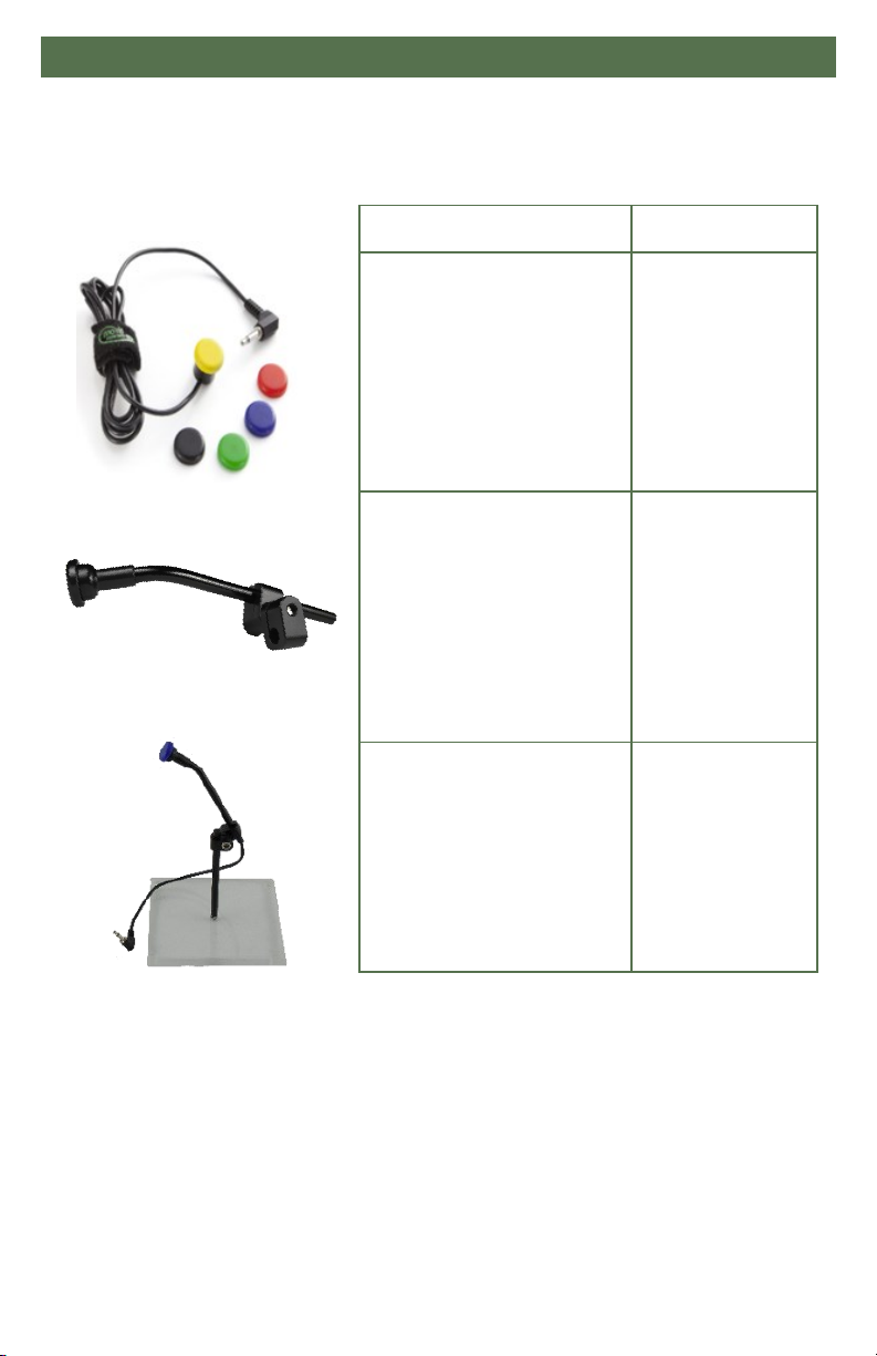
Product Description Part Number
Twister Basic Cable
(available in 5 colors)
Yellow (IDM-24)
Black (IDM-25)
Red (IDM-26)
Blue (IDM-27)
Green (IDM-28)
Twister on Bent Tube, Long
Cable (1500mm)
Red (IDM-34)
Black (IDM-35)
Yellow (IDM-36)
Blue (IDM-37)
Green (IDM-38)
Twister on Bent Tube, Short
Cable (300mm)
Black (IDM-41)
Red (IDM-42)
Yellow (IDM-43)
Blue (IDM-44)
Green (IDM-45)

4
Parts And Accessories 8.0
Specifications 8.2
Product Description Part Number
Satellite Twister
(Compatible with All-Round
Joystick only)
Red (IDM-17)
Black (IDM-18)
Yellow (IDM-19)
Blue (IDM-20)
Green (IDM-21)
Twister Dome Switch
Red (IDM-53)
Black (IDM-54)
Blue (IDM-55)
Green (IDM-56)
Yellow (IDM-57)
Action Description
Switch Type Mechanical, Normal Open
Connection Type Wired
Activation Type Pressure
Activation Surface Diameter .67in (17mm)
Travel Before Activation .02in (.5mm)
Activating Force 30g (.067 lbf)
Feedback Auditory Click, Tactile
Plug Size 1/8” (3.5mm) mono jack
Cable Length 59.05in (1500mm)

5
Installation Instructions 9.0
Preparations 9.1
Only a qualified service technician may install the Twister switch.
Use the proper tools to install and adjust the Twister switch. The use of
improper tools may cause damage to the device.
Installation Plan 9.2
Set up an installation plan before beginning the installation. This plan should
take into account:
Where the Twister switch should be placed on the chair.
What funcons you would like for this switch to do.
The posioning of the basic twister switch. Do not place any of the Twister switches
where they may be obstructed from performing the funcon they were intended for.
CAUTION
Any connection must always be secured with all delivered screws. Only use the
screws provided in the package.
WARNING All wheelchair electronics must be switched off.
WAR NING
An incorrect programming of the wheelchair electronics may cause damage to
the devices or injury to the user.

6
Installation Instructions 9.0
Twister On Bent Tube 9.3
Diameter of Twister rod-6mm (.236in)
Length of Twister rod-100mm (3.94in)
Each Bent Tube is provided with a Quick-to-Mount clamp that splits in 2 parts in
order to allow the cable to run through the switch. It can be mounted on a 6mm rod.
Compable with any joysck but cannot be mounted onto the All Round Joysck.
1. Slide Q2M Clamp onto and 6mm rod (compable with Power Chin Boom, C-Rod or S-Rod).
2. Adjust the height of the twister switch by sliding it along the split clamp provided.
3. When the switch is at the desired height, use a 3mm T-Handle to ghten the clamps on the
tube.
4. Plug into the power or mode inputs on the joysck.
Twister Basic 9.4
The Twister is mounted on a plate of metal/plasc with 2 screws. A regular Phillips
Screwdriver is required to mount screws.
2 Types of screws delivered:
-Diameter 2.2mm (0.087 in)
Length 6.5mm (0.266in) for sheet thickness 0.5mm (0.02 in) to 2mm (0.079 in)
-Diameter 2.2mm (0.087 in)
Length 9.5mm ( 0.374in) for sheet thickness 3mm ( 0.118 in) to 4.5mm ( 0.177 in)
The screws are self-tapping metal screws (A2 stainless steel).
Compable with any joysck.
7
Installation Instructions 9.0
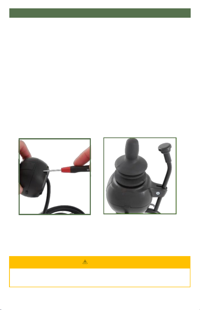
Satellite Twister 9.5
The Satellite Twister comes with a special All-Round insert. This ts only into the housing of
the All-Round Joysck.
Diameter of Satellite Twister rod- 6mm (.236in)
Length of Satellite Twister rod- 100mm (3.94in)
You can mount one or two Satellite Twisters to the All-Round Joystick.
1. Dene the locaon of the Satellite Twisters: le, right, or on both sides.
2. Unscrew and remove the cover for the Satellite Twister connecon with a
Phillips screwdriver.
3. Place the Satellite Twister rmly into the open slot.
4. Use the screw of the cover to secure the Satellite Twister to the All-Round Joysck.
5. If required, place a second Satellite Twister in the same way.
6. Connect the cabling of the Satellite Twister to the All-Round Joysck.
To adjust the height of the switches:
1. Loosen the set screw on the clamp with a 2.5mm T-Handle.
2. Adjust the switch to the desired height.
3. Once in posion, ghten the set screw to hold the Twister switch in place.
CAUTION
Tighten the screws firmly, but not excessively. Excessive force may damage
the unit.
8
Installation Instructions 9.0
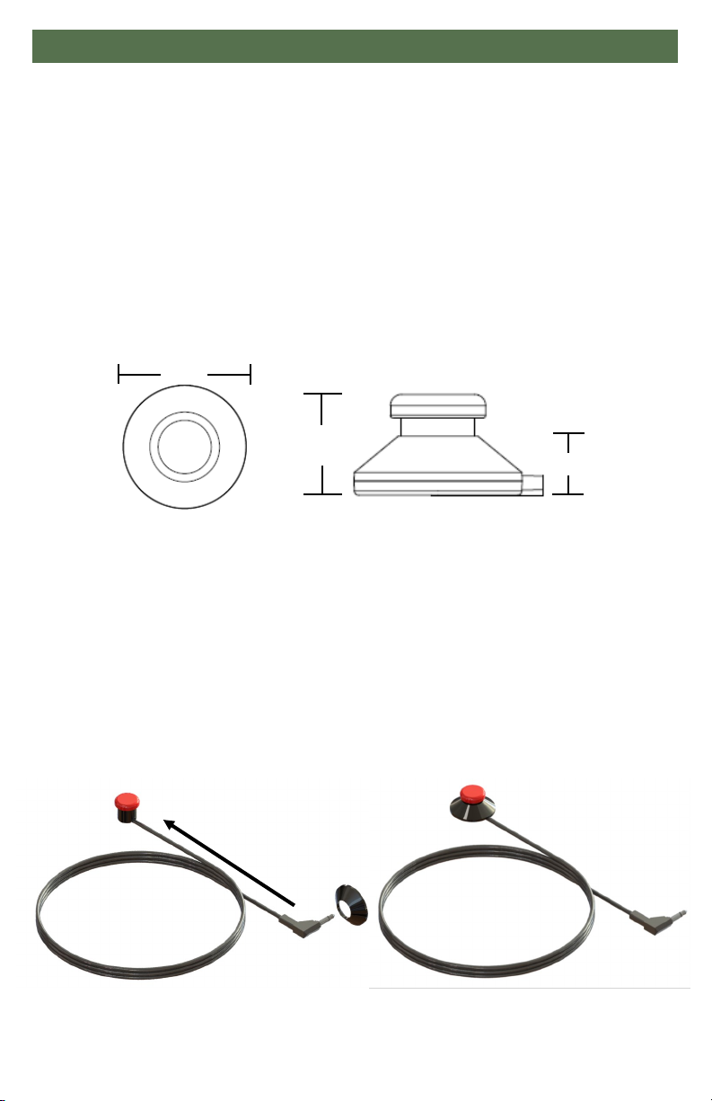
Twister Dome Switch 9.6
Included in each Twister Dome Switch Package:
Set 3M Dual Lock interlocking self-adhesive fasteners 25mm x 2mm (0.866in x 0.078in)
1 self-adhesive rubber pad 28mm x 2mm (1.102in x 0.078in)
2 Types of self-tapping screws delivered:
-Diameter 2.2mm (0.087 in)
Length 6.5mm (0.266in) for sheet thickness 0.5mm (0.02 in) to 2mm (0.079 in)
-Diameter 2.2mm (0.087 in)
Length 9.5mm ( 0.374in) for sheet thickness 3mm ( 0.118 in) to 4.5mm ( 0.177 in)
To replace the Twister button:
1. Feed the top of the casing from the end of the Twister cord up to the base of the Twister
buon. See Figure 1.
2. The buon should rest along the top cut-out of the casing. See Figure 2.
3. Ensure the Twister cable is placed along the cable cutout area in the casing.
4. Align the Twister holes on the top of the dome casing with the Twister buon and with the
pre-drilled holes on the base of the casing.
5. Tighten and secure the casing along the base with the four provided screws. The two inner
screws will hold the buon in place. The 2 outer screws will secure the casing.
Figure 1 Figure 2
.71” .413”
1.18”

9
Installation Instructions 9.0
To use the interlocking self-adhesive fasteners:
1. Remove the adhesive backing on one of the self-adhesive fasteners and place on the
boom of the Dome Switch casing.
2. Remove adhesive backing on the second fastener and place adhesive side down on at
surface.
3. Place the Dome Switch casing with the fastener on top of the fastener secured to the at
surface. Press down unl you hear a clicking sound indicang the fasteners are secured to
each other.
To adhere the rubber pad to the Dome Switch casing:
1. Remove the adhesive backing from the rubber pad and place on the base of the Dome
Switch casing.
2. Rubber pad with Dome Switch is not permanently secured to the surface. The placement
can be changed when necessary.
NOTICE
The dome switch casing cannot be replaced.

10
Functioning 10.0
Operating The Twister 10.1
The Twister switch is a single, mechanical, normal open switch. It will activate
when pressed on.
To activate your Twister, simply press anywhere on the top of the activation
surface. You will feel and hear a clear and audible “click”.
Twister Safety 10.2
Do not use if the Twister handle is damaged, the top is cracked, or missing.
Do not use if the Twister does not properly make an audible noise when applying pressure.
Do not use if the Twister does not move when applying pressure.
Safe Driving 10.3
It is mandatory to have a wheelchair power on/off switch, which immediately
shuts down the wheelchair power and electronics, within easy reach of the user
while driving. This allows the wheelchair to instantly stop in case of problems or
an emergency.
In case the wheelchair responds in an unexpected way, the user must
immediately release the power switch.
WAR NING
Make sure that cabling is mounted in such a way that excessive wear and tear
is avoided.
WARN ING The on/off switch must be available to the user at all times.

11
Testing 11.0
After installation of the Twister, execute the following tests before the
wheelchair is delivered or put into service:
Check That The Twister: 11.1
Is not bent or damaged.
Housing, cabling, and all connectors are not damaged.
Makes the audible “clicking” noise and returns back to its original posion.
Operational Test: 11.2
Acvate the wheelchair operang system.
Check for any error message.
By pressing the desired switch, the programming funcons should either turn o/on, or
highlight through chair funcons.
Repeat the previous steps a few mes in order to conrm the switches are
acvang correctly.
Test Drive: 11.3
Perform a test drive with the wheelchair.
Check whether the wheelchair and all of its opons are fully funconing in all posions the
user may need with the selected joysck and Twister switch.
Check that no cabling or parts could possibly get damaged or hindered in any possible
posion of the wheelchair.
Stop Test: 11.4
Drive full speed ahead and shut down the wheelchair with the power on/o switch.
The wheelchair may not suddenly stop, but must slow down to a gradual stop.
WAR NING
Execute this test only on a level surface, in an open area free of obstacles.
CAUTI ON The wheelchair may start moving.

12
First Time Use 12.0
Dealer Assistance 12.1
During first time use by the client, it is advised that the dealer or service
technician assists and explains the different drive configurations to the
customer (the user and/or the attendant). If needed, the dealer can make
final adjustments.
User Testing 12.2
It is important that the customer is fully aware of the installation, how to use it,
and what can be adjusted in order to gain as much mobility as possible. As a
dealer, proceed as follows:
Explain and show the customer how you have executed the installaon and explain the
funcon of every (new) buon.
Is the joysck and the switch within easy reach?
Can the user safely operate the wheelchair with minimal eort?
Is the placement of the joysck with the aached switch available in an opmal posion
for the user?
If needed, adjust the Joystick to the proper position so the Twister is in a
better position for the client to operate.
Explain to the customer possible problems and how to address them.
Conditions Of Use 12.3
The Twister is intended for use as installed by the dealer, in accordance to the
installation instructions in this manual.
The foreseen condions of use are communicated by the dealer or service technician
to the user and/or aendant during the rst me use.
If the usage condions change signicantly, please contact your dealer or a qualied
service technician to avoid excessive wear and tear or unintended damage.

Maintenance 13.0
13
Cleaning 13.1
To keep the Twister functioning properly:
Disconnect Twister and wipe clean with a damp cloth.
Use only non-aggressive disinfectant cleaning agents. Cleaning soluons that
contain bleach, ammonia, chlorine, etc. should not be used. (Dish washing cleaners
are acceptable.)
Never immerse the Twister in water or cleaning soluon.
Monthly 13.2
Monthly or when needed, check whether:
All bolt and screws are sll rmly ghtened.
There is no damage to any wiring.
There is no excessive wear to any of the parts.
WARN ING Do not pull or wrap the cable around the Twister.
WAR NING
Do not attempt to open or disassemble the Twister enclosure.
Table of contents
Other Mo-vis Switch manuals


