Mobile Awareness MA-ODSS-4M17WA Service manual

Parking sensor system
Parking Sensor System
For Commercial Trucks, Utility Vehicles, Buses, Motorhomes and SUV's
INSTALLATION&INSTRUCTIONMANUAL
Model:MA‐ODSS‐4M17WA

Parking sensor system
1 of 7
●PRODUCT COMPOSITION
CONTROL UNIT (ECU) WARNING UNIT DETECTION UNIT
•Dimensions:
4.3(L) x 3.6(W) x 1.25(H) in.
110(L) x 92(W) x 32(H) mm
•Accessory for Installation:
- Hexagonal bolt M6X10: 2pcs
•Dimensions:
3.5(W) x 2.9(L) x 1.6(H) in.
90(W) x 75(L) x 40(H) mm
•Accessory for Installation
- Adhesive tape
- Cable clip: 2pcs
•Type of Sensor:
Recess type/Bolt-in type
•Sensor Model:
M17
•Quantity:
- 4 Each + mounting screws

Parking sensor system
2 of 7
●TECHNICAL DATA
NO.
ITEM DATA
NO.
ITEM DATA
1 Display Distance 0.22~2.5(m)
0.72~8.20(ft)
6 Working Voltage
10.5~28.0(VDC)
2 Blind Area (at 25 ºC) <0.22m <8.7 inches
7 Rated Voltage 12.0 VDC
3 Detection Tolerance (at 25 ºC) ±0.02m ±0.8 inches
8 Rated Current ≤250 mA
4 Warning Mode LED & Sound
LED & Sound
9 Working Temp. -30 ~ +80 (ºC)
5 Transmitting Distance (Open field)
>120m >390 ft
10
Storage Temp. -40 ~ +90 (ºC)
●FUNCTION
Warning
Zone Distance from Sensor and Obstacle Visual Signal
LED Bar Distance
Acousticall Signal
S2,S3 S1,S4
Danger
Zone
Caution
Zone
Safety
Zone
Note
Bi
(continuous)
Bi
(continuous)
Bi.Bi.
Bi..Bi..
Bi...Bi...
Bi....Bi....
Soundless
Soundless
Soundless
Bi.Bi.
Bi..Bi..
Bi...Bi...
Bi....Bi....
Soundless
Soundless
Bi.....Bi.....
(1) "D"-Numeric Display in Digits; (2) S1~S4-Sensor's serial Number
"-P-"
"D"
"D"
"D"
"D"
"D"
"D"
"D"
0 D 0'09''
0'09'' D 1'00''
1'00'' D 1'04''
1'04'' D 2'00''
2'00'' D 2'07'
2'07'' D 3'03''
3'03'' D 5'07''
5'07'' D 6'07''
6'07'' D 8'02'' "D"
Unit: f t
Unit: m
0 D 0.22
0.22 D 0.30
0.30 D 0.40
0.40 D 0.60
0.60 D 0.80
0.80 D 1.00
1.00 D 1.70
1.70 D 2.00
2.00 D 2.50

Parking sensor system
3 of 7
●ABOUT THE DISPLAY
(1) Indication of direction and zone: the 4 columns of LED bar show the
direction and location of the obstacle;
(2) Indication of distance: shows the distance from
the sensors to the obstacle in meters or in feet
.
●INSTALLATION
▲WHERE TO INSTALL OF ECU
Install the ECU on the rear part of chassis and the
warning unit somewhere above the dashboard.
▲INSTALLATION
Install the ECU at an appropriate place on the chassis with the enclosed bolts
M6X10.
▲INSTALLATION OF DETECTION UNIT
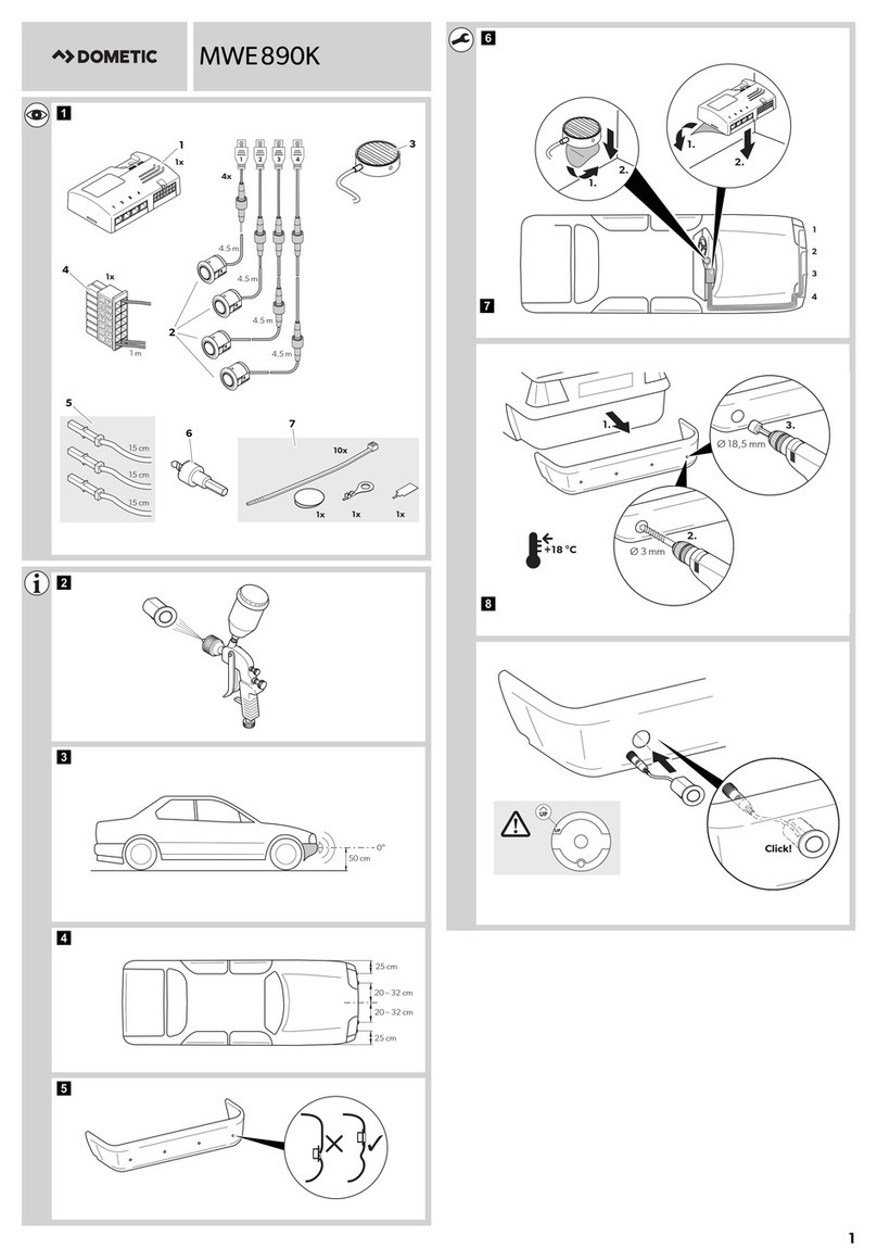
(1) Since the width of different vehicle models varies, it is

Parking sensor system
4 of 7
important to install sensors at right places.
Suppose the width of vehicle is L, then,
(a) For 4-channel systems, the space between sensors is 1/4L;
(b) For 3-channel systems, the space between sensors is 1/3L;
(c) For 2-channel systems, the space between sensors is 1/2L.
(2) Sensors should be mounted 16 in. (40cm) to 32 in. (80cm) from the ground, but 20 in. (50cm) is the best choice,
if available.
(3) How to install sensors
Ex: Sensor A
(a) With a drill bit M5, make 2 holes spaced 1.5 in. (38.3mm) apart and
no more than 0.6 in. (15mm) from the edge of the bumper or similar
vehicle fixture.
(b) As the right fig. shows, attach the sensors on the bumper or similar
vehicle fixture (metal bar, etc.) with the enclosed mounting hardware.
(c) When needed, the sensor’s vertical angle can be adjusted by
placing a shim between the bracket and bumper.
●CONNECTION BETWEEN UNITS
(1) Connect the ECU power cable red wire (+ voltage) to the reverse light
and the black wire to ground;

Parking sensor system
5 of 7
STOP
FtM 22
33
4 4
1 1
Red +
Black -
ECU
Sensor S1~S4 PK-012BL201M
Display:LED4
Sensor Wire
Power Cable
Length=1.2m
M6X20 2PCS
Display Connecting Wire
Sensor Wire
Sensor Wire
Sensor Wire
Important: never reverse the power polarities.
(2) Attach each of the sensors to same numbered waterproof
connector running from the ECU (S1 to S1, S2 to S2, etc.);
(3) Refer to the diagram on the right for additional connection information.
●HOW TO SET FUNCTIONS
(1) With Volume Switch, adjust the alarm volume at 3 levels: High, low or off;
(2) Click Setting Button twice, the distance will be displayed in meters or in feet;
(3) Identification of ECU: this function is
designed for vehicles, which may work with
a multitude of trailers.
(4) Stop-line adjustment
This function is designed for adjusting the
stop line of the parking sensor system.
Parking sensor systems usually report the
distance from the bumper to obstacles, so
the bumper or exactly the sensor surface is
the “0” point of distance. With this function,
the so-called “0” point itself can be
extended from 0 up to 31 inches (0.8m),
enabling you to change the stop line
accordingly. In some circumstances, for
instance, when the vehicle has a rear carrier for a spare tire or
similar item, the “0” point should be extended. By doing so the

Parking sensor system
6 of 7
parking sensor system doesn’t report the carrier, but reports the accurate distance from the obstacle to the carrier,
instead of to the bumper (see the vehicle example).
How to set
(a) Press and hold Setting Button, before and when turning the vehicle key to ACC position.
(b) In 3 seconds, the warning unit will show some digits which are the previous “0” point of distance.
(c) Each time you press the button, the displayed “0” point of
distance increases by 0.01(m), until 0.8m (31 inches), and then
starts at 0 again. However if you press and hold the button for
about 2 seconds, the value will increase automatically, hold the
button until the value reaches the desired corrected distance
and fine tune as needed.
(d) After the button is released, wait for 5 seconds, the re-set
value will be effective automatically.
●HOW TO USE
▲STARTUP
When the reverse gear is engaged, the system is automatically powered on, and beeps once, before starting the
diagnostic mode.
▲DIAGNOSTIC MODE
(1) Once powered on, the system starts diagnostic mode.
(2) If some sensor is found abnormal, the system will beep once, “EX” will be displayed for less than 3 seconds, “X”
is the serial number (1~4) of the abnormal sensors

Parking sensor system
7 of 7
Ex 1: If “E4” is displayed, it tells you the sensor No. 4 doesn’t work.
Ex 2: If neither sensor No. 2 nor No. 3 works, “E2” and “E3” will appear in the display successively.
If none of the sensors work, “EE” will be displayed, the speaker will keep beeping for 1.5s and the system will not
operate.
(3) After 3 seconds of diagnostics and possible failure warning, the system begins working, although with abnormal
sensors, if any.
Note: Warning unit will never alert you of any obstacles behind the abnormal sensor(s) and the relative
indication of direction will disappear.
●PRECAUTION
The sensor surface must be kept clean; water, ice or mud left on it may affect its performance. The detection results
may be affected when the system operates in extreme weather conditions (e.g. strong wind, heavy rain, and snow,
very low or high temperature) or on complicated roads (such as rugged roads or roads with slope). Ultrasonic and
electromagnetic fields from other sources near the system, if any, may affect the detection results.
●LIABILITY DISCLAIMER - USE OF PRODUCT
The system is designed and intended as a warning aid for vehicle backing and parking, and it should only be used as
such. No warranty as to operational efficiency is granted. In no event shall Mobile Awareness, LLC be liable for
consequential, incidental or special damages or for installation, adjustment, or other expenses which may arise from
the use of this product. Mobile Awareness, LLC shall in no event be liable for any direct or indirect damages, including
personal injury or death, resulting from errors that occur in the use of this product, irresponsible acts, unsafe driving
or negligence. By purchasing, installing and using this merchandise, the customer agrees to take full responsibility
for the safe operation of the vehicle while using this product.
Parking sensor system
8 of 7
FCCWARNING
ThisdevicecomplieswithPart15oftheFCCRules.Operationissubjecttothefollowingtwo
conditions:
(1)thisdevicemaynotcauseharmfulinterference,and
(2)thisdevicemustacceptanyinterferencereceived,includinginterferencethatmaycause
undesiredoperation.
NOTE:ThemanufacturerisnotresponsibleforandradioorTVinterferencecausedby
unauthorizedmodificationstothisequipment.Suchmodificationscouldvoidtheuser’sauthority
tooperatetheequipment.
Table of contents