5
Installing the Deection Sensors
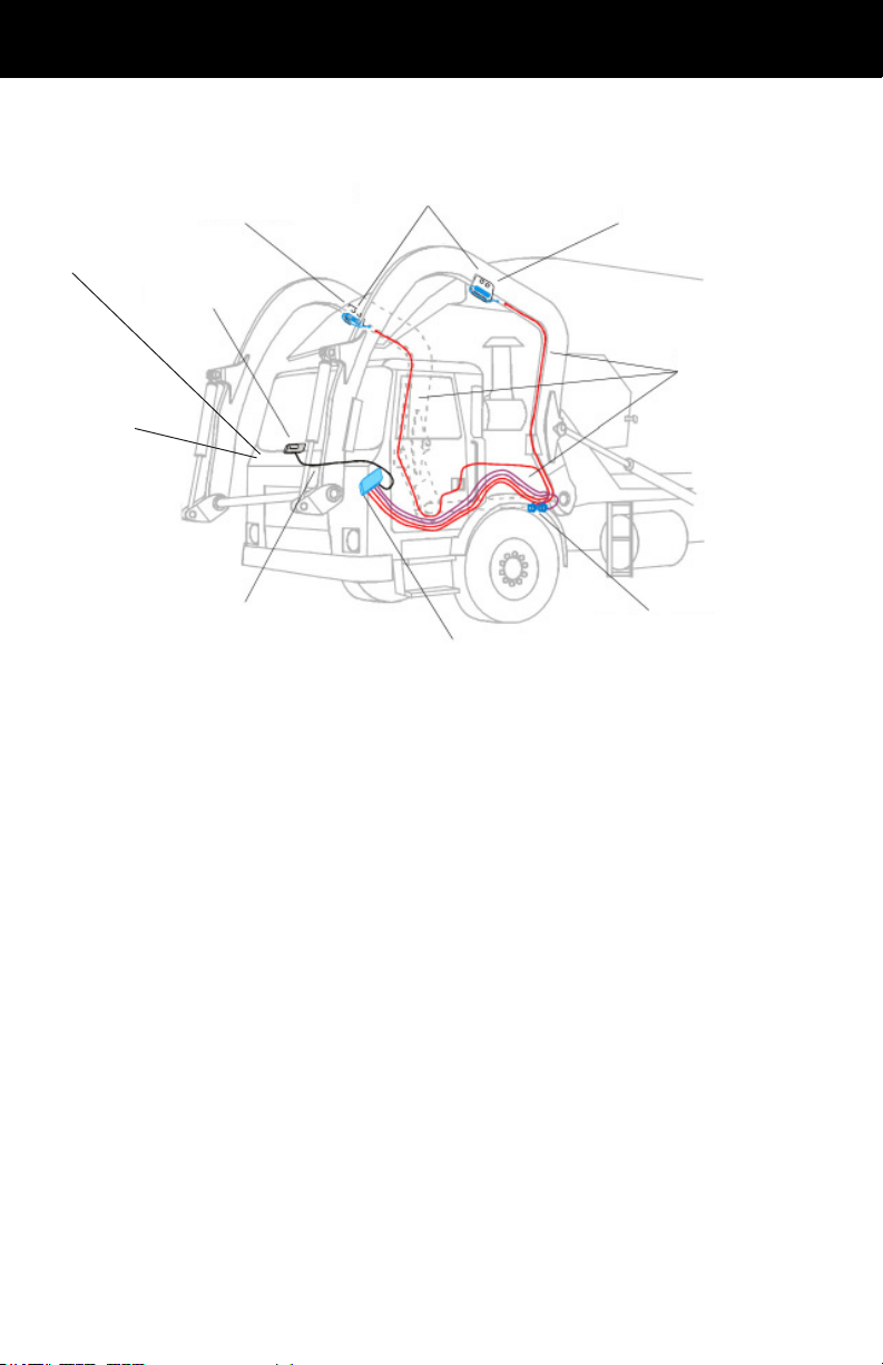
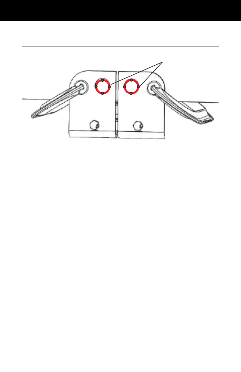
Thedeectionsensorsmeasuretheexintheliftarmsasthetruck
raisesandlowersbins.BinMaxxusestwosensors,oneforeach
arm.Eachsensorismountedtoasetofarmbracketsoneachside
ofthetruck.
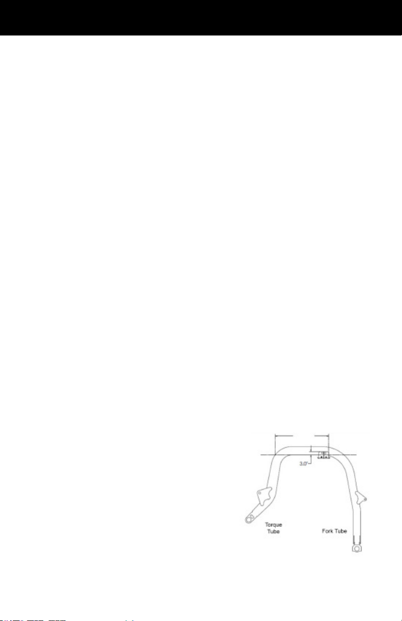
Choosing a Location for the Brackets
• Thebracketsshouldbeasclosetotheupperforward
curve(closesttotheforksofthetruck)whileremaining
level(i.e.notinthecurve).
• Thebracketsshouldnotbeplacedoveranyhydraulic
clamps,couplersorotherhardware.(OEMweldsmay
needtobegrounddowninordertoplacetheBinMaxx
armbracketinthemostoptimumlocation.)
• Thebracketsand/orarmsensorscannotbeincontact
withanyothertruckcomponent,suchasanarmmounted
hydrauliclineoranarmcable.
• Thebracketsneedtobeplacedinthesamepositionon
botharms.Verifypositioningonbotharmspriortowelding
thebracketsoneitherside.Ensurethattheposition
chosen does not have any interference on either side.
• Thebracketsshouldbeplacedsothatthereisenough
spacetoinstallorremovethedeectionsensors.Leave
thealignmenttool(Jig)inthebracketduringweldingto
ensurethatthereisenoughspace.
• If an arm weld seam or plug is located in the optimum
position for the arm
brackets, grind the arm weld
seam down until it is smooth
and ush with the arm and
then position and weld the
arm sensor brackets to that
location. Positioning of
the scale’s brackets must
supersede the existence
of any OEM welds when a
conict occurs.
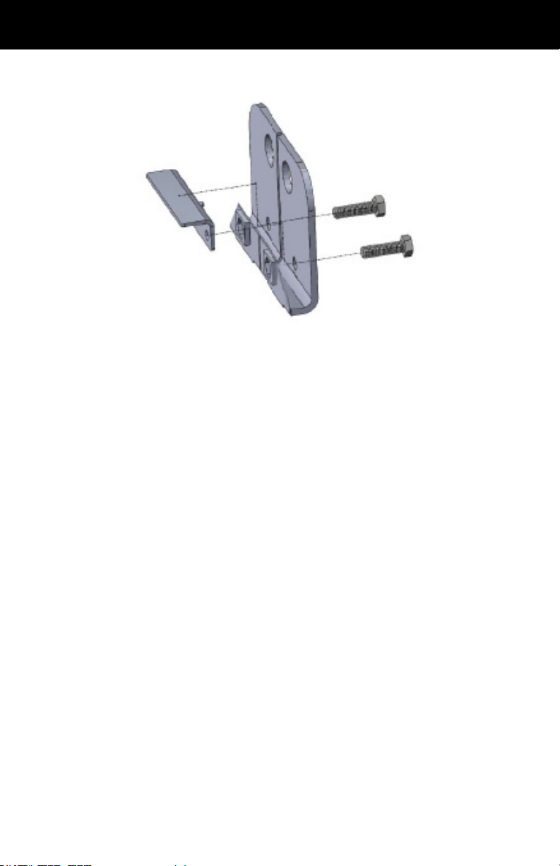
Placing the Bracket on the Lift Arm