CARLO GAVAZZI SBPVBE User manual

VIDEOBOX
USER MANUAL
Feb. ’20

Videobox –User manual
2
Index
Index.......................................................................................................................................... 2
Updated version......................................................................................................................... 3
Important notes.......................................................................................................................... 4
Safety notes........................................................................................................................... 4
Preventive precautions for installation................................................................................. 4
Glossary .................................................................................................................................... 5
System requirements.............................................................................................................. 5
General description.................................................................................................................... 6
Architecture......................................................................................................................... 7
System overview.................................................................................................................... 8
Things to know.................................................................................................................... 8
Positioning of the IP cameras ............................................................................................10
Network design......................................................................................................................15
Things to know...................................................................................................................15
SBPVBE videobox installation...................................................................................................19
Things to know......................................................................................................................19
Further readings ................................................................................................................19
Installation guidelines............................................................................................................20
SBPVBE configuration...........................................................................................................22
Pre-Requirements..............................................................................................................22

Videobox –User manual
3
Updated version
Content subject to change.
Download the updated version: www.productselection.net

Videobox –User manual
4
Important notes
This section contains important safety-related information to be followed when installing,
operating and maintaining the equipment. We strictly recommend respecting these rules to
avoid damages to devices or machinery and injury or death to people. Please read this manual
carefully before beginning any installation, maintenance or operational activity.
▪
Electrical components constantly under high voltage
▪
Important information for safety and to prevent physical damage
▪
Important information for a proper use of the system
Safety notes
Preventive precautions for installation
All personnel involved in the installation of the sensor must use appropriate PPE
(Personal protective equipment) in compliance with Legislative Decree no. 9 April
2008, n. 81 "Consolidated Law on Health and Safety at Work" (text coordinated
with Legislative Decree 3 August 2009, No. 106).
All personnel involved in the installation of the sensors or must comply with the
recommended limits for lifting and manual transport in compliance with Legislative
Decree no. 9 April 2008, n. 81 "Consolidated text on health and safety at work"
and technical standard UNI ISO 11228.
In any case and following the failure to comply with the above, Carlo Gavazzi declines all
responsibility for any damage caused to persons and / or property during or following the
installation of the sensors.

Videobox –User manual
5
Glossary
Parking bay: parking space for vehicles delimited by strips (blue, white, yellow)
System requirements
We assume that installers have a basic understanding of computers, Microsoft Windows and
networking.
▪SBPVBE videobox
One SBPVBE videobox for up to 8 IP cameras
▪IP cameras
The IP cameras must meet the system requirements
▪Network devices
Network devices such as Ethernet switches or W-LAN adapters to connect the IP cameras to
the SBPVBE videoboxes
Computer with Windows 10 or later
A PC is required to configure the SBPVBE videobox. TeamViewer/Anydesk must be installed
Internet access
The SBPVBE must have Internet access. If a LAN network is not available, a 4G/LTE router
must be used

Videobox –User manual
6
General description
The SBPVBE videobox is part of the Carpark system, which contains other variants of sensors,
controllers and displays. We briefly describe the SBPVBE videobox parts:
Part
Description
A
Plug connector for 12 VDC. Included AC power adapter specifications:
Input
Output
100-240 VAC, 50/60Hz
12 VDC, 5A (60W)
B
Power button
C
L-shape mounting brackets for DIN-rail or VESA mounting
D
1x Gbps LAN port
E
LED indicators

Videobox –User manual
7
Architecture
The SBPVBE videobox uses IP cameras to detect cars parked in outdoor parking lot. A
sophisticated algorithm converts the camera images into occupancy information: no sensitive
data (car plate number, people’s faces, etc.) are either sent over the Internet or stored. This
information will be sent to the cloud in real-time and the CPY Server gathers the information by
means of the cloud.
Element
Component
Function
A
SBPVBE videobox
It converts the video-stream into data (occupancy
information) and it sends them to the cloud server.
B
IP cameras
They take the pictures of the parking area.
C
Parking bays
D
UWP 3.0/SBP2CPY
System
It gathers occupancy information from the cloud.

Videobox –User manual
8
System overview
This manual describes the procedures to install the SBPVBE Car Park videobox and gives
general instructions to properly place the IP cameras used to detect cars in the parking bays.
Things to know
Each SBPVBE videobox can handle a maximum of 8 IP cameras, therefore, the minimum
number of videoboxes for covering an area is the number of IP cameras divided by 8. One
camera detects an average of 40 parking bays: this depends on the mounting height,
positioning and technical specifications of the IP camera. The videobox works with a wide range
of standard IP cameras, even with those already present in the installation if the framing and
positioning are compatible with the system requirements.
Since the IP cameras are installed in outdoor spaces, their choice should be properly evaluated
according to the weather conditions (fog, cold, humidity, etc.). In case of fog it is essential to
equip the IP camera with a fog filter.
Day & night condition
Since the detection algorithm operates continuously, the IP cameras must be able to detect the
parking bays also at night time. This means that the parking areas must have an adequate light
level.
If the light level is not adequate, or too low, the IP cameras may not recognize the cars and
consequently, the occupancy information might be wrongly managed. Should this be the case, it
is suggested to evaluate IP cameras with built-in IR functionality which ensures that cars can be
detected in dark conditions.
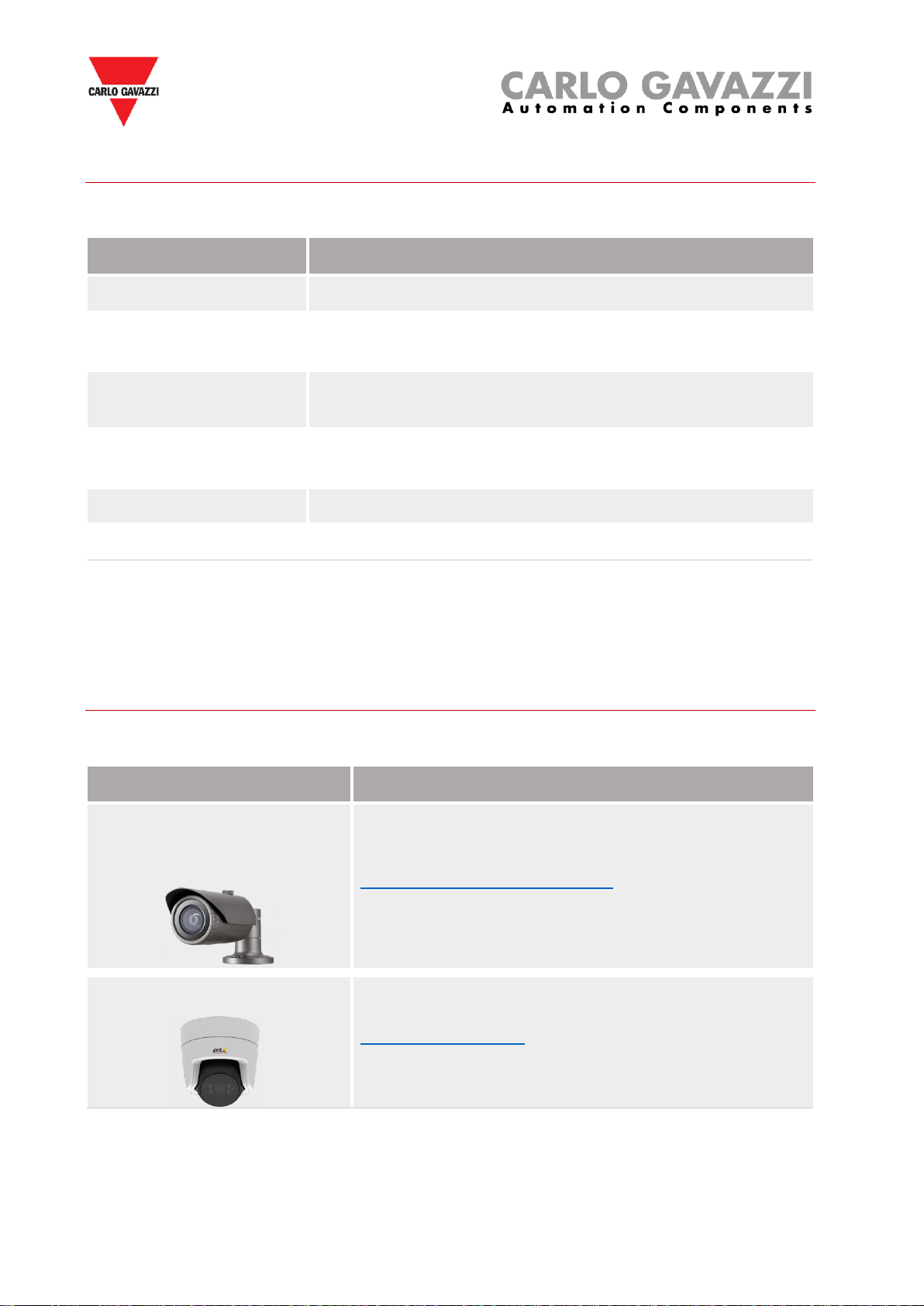
Please be aware that most of the IP cameras available in the market, even working without the
IR functionality, have better low light response than the human eye. The minimum illumination
specification refers to the lowest light level (Lux) an IP camera is able to recognize the
environment.
Refer to the IP Camera’s manufacturers documentation. See the example below:
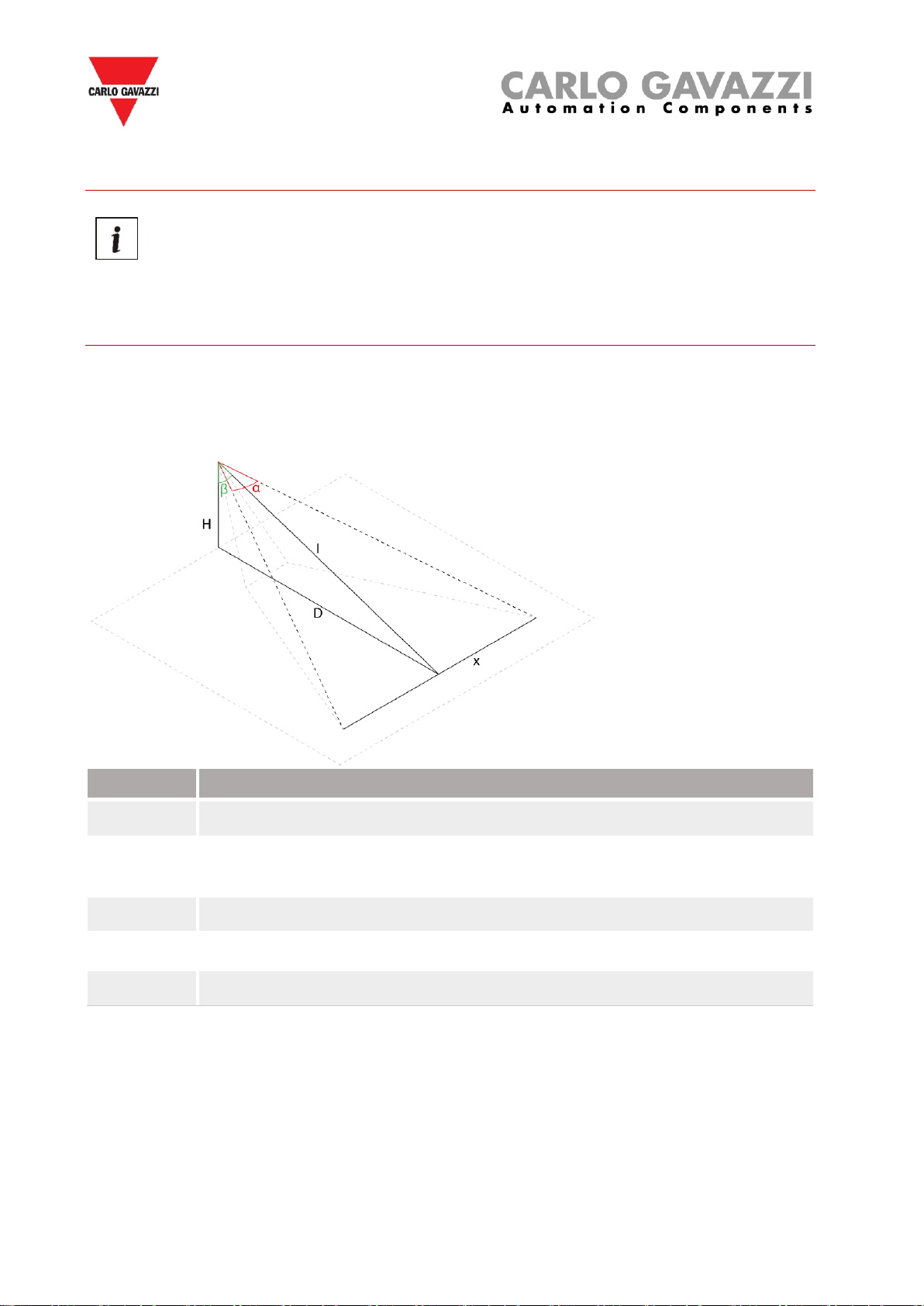
Note: Please consider that the distance between the IP camera and the furthest car must be
less than the IR Viewable length an IP camera is capable of.
The installation of the system is designed for outdoor spaces (see the SBPVBE videobox
installation procedure)

Videobox –User manual
9
Recommended IP camera specifications
The table below shows the recommended IP camera specifications:
Feature
Requirement
Video resolution
2 (Minimum) / 4/ 8 Mpx
Pan / tilt / zoom
They must be disabled before configuring the camera with the
SBPVBE algorithm
Video data transmission
method
LAN network through UTP/STP cable, better if PoE
4G/LTE network (router is not included)
Required protection
degree
For an outdoor installation: IP66 or higher
Video compression
H.264, H.265, MJPEG
Protocols
RTSP, TCP
Note: Regular maintenance guarantees correct functioning of the system. Keep the IP camera’s
lens clean.
Suggested models
Below some IP cameras are listed which meet the recommended requirements:
Model
Manufacturer
Hanwha Techwin QNO-7010R
Hanwha Techwin QNO-7020R
Hanwha Techwin QNO-7030R
https://www.hanwhasecurity.com/
Axis M3106-LVE Mk II
https://www.axis.com/

Videobox –User manual
10
Positioning of the IP cameras
The verification of the site where the IP cameras will be installed is a very important
phase: the environmental and physical conditions must be evaluated to avoid
detection problems.
Calculation of the covered area
The IP cameras must be positioned at a minimum height of 8 meters (recommended 10 meters)
in order to achieve the best coverage.
Consider the following diagram, which graphically shows an assembly configuration:
Parameter
Description
H
Represents the mounting height of the IP camera (min 8 meters)
D
Represents the distance (measured on the ground) between the pole where
the IP camera is installed and the parking bays
α
Defines the viewing angle of the IP camera (depends on the IP camera)
β
The angle of tilt (e.g. the angle of tilt of the camera related to the ground)
I
Hypotenuse: To calculate the distance use Pythagoras’ Theorem: √ (H² + D²)
The x value indicates the field of view of the IP camera. This value refers to the parking bays
that have to be covered, so this is useful to calculate the total number of IP cameras that have
to be used to cover an area.
To calculate the x value, use the following formula:
𝒙 = 𝐼 ∗ 2 ∗ 𝑡𝑎𝑛(𝛼/2)

Videobox –User manual
11
Field of view calculator
Camera’s manufacturers generally provide tools to calculate the field of view. The Field of View
Calculator is a program for calculating the IP camera’s visible scene. Fill in the lens format and
focal length and distance between lens and object, it will then work out the dimensions of the
scene.
For example, here is a link to Hanwa's Field of View Calculator for the Wisenet camera NO-
7010:
https://www.hanwha-security.com/wisenettoolbox/index.html#/en/home

Videobox –User manual
12
Distance and resolution of the IP camera
The minimum resolution of the IP camera must be evaluated according to the spaces in the
installation: the greater is the distance between the IP camera and the parking bays, the higher
will be the IP camera resolution.
The positioning is constrained by the camera resolution: a resolution of at least 50x50 pixel is
needed to properly detect the car in the parking bay.
To summarize, these are the guidelines to place the IP camera:
▪Install the IP cameras at a minimum height of 8 meters.
▪The minimum distance (measured on the ground) between the nearest parking bay and
the IP camera must be at least 5 meters.
▪The IP cameras must be placed in the opposite side of the road from the parking bays
and minimizing the presence of any obstacles, type vegetation or other.
▪Each parking bay must be delimited by painted strips.

Videobox –User manual
13
Example of positioning the IP camera
Please follow the suggestion below, to define the position of the IP camera. The following
examples show general cases of configurations to be adopted or avoided:
Right mounting example
Wrong mounting examples
N.B. In case of other types of parking facilities or in case of doubts about the positioning of the
IP cameras, please contact us.

Videobox –User manual
14
Numbering the parking bays
Arrange a scaled map of the parking area and number every parking bay with an individual
number.
The total number of parking bays is
Start the parking bays numbering with
less than 100
101
between 100 and 1000
1001
higher than 1000
10001
See the indication below to number the parking bays:
Assign to each parking bay a number in line and sequentially as shown below:
Avoid the numbering as below:

Videobox –User manual
15
Network design
The IP cameras can be connected to the SBPVBE videobox by using network devices, such as:
Device
Description
Ethernet switches
The SBPVBE are connected to the same LAN network by using
Ethernet switches.
W-LAN adapters
The SBPVBE are connected to the same LAN network by using W-
LAN adapters.
To connect the webcams mounted on other poles to the main pole
where the SBPVBE is installed
The number of network devices such as Ethernet switches or PoE adapters (and
SBPVBE videoboxes) depends on the parking area to be monitored and on the IP
cameras needed to cover it.
Below general guidelines are proposed to help the installer to calculate the number of required
network devices.
Things to know
One or more Ethernet switches are required to connect one or more SBPVBE videoboxes to
one or more IP cameras on the LAN network. The LAN network must have Internet access
and a DHCP Server. If a LAN network is not available, a 4G/LTE router must be used (the
router and the SIM card are not included).
Recommended Ethernet switches specifications
The table below shows the recommended Ethernet switches specifications:
Feature
Specification
Port Standards
IEEE 802.3, TCP/IPv4, TCP/IPv6
Interface
100/1000 Mbps port, RJ45 connector
Number of ports
According to the number of devices (videobox, IP cameras) that have to
be connected in the same cabinet
Switching capacity
See paragraph below
PoE
IEEE 802.3at-compliant
Note: For Power over Ethernet (PoE) ports to supply the IP cameras,
the installer has to consider switches that support this technology, so
that a single UTP/STP Ethernet cable can be used for power supply
and data

Videobox –User manual
16
Calculation of the overall switching capacity
The network devices, such as industrial switches or PoE switches, should be selected according
to the switching capacity that is required by all the IP cameras that are used in the installation.
The following table shows the bandwidth assessment for streams of different types and
resolutions per used camera.
Resolution
Minimum bandwidth
H.264
H.265
FullHD@30fps
~ 8 Mbps
~5 Mbps
4K@30fps
~ 28 Mbps
~ 18 Mbps
Note: Please refer to the camera’s manufactures documentation
Example
To calculate the overall switching capacity, the sum of the bandwidth consumption of all the IP
cameras has to be calculated. For example, if 4K and FullHD cameras are used, the total
consumption has to be calculated following the column Bandwidth consumption in the table
below . H.264 video compression has been selected for all the IP cameras:
Resolution
Quantity
Bandwidth consumption
4K
2
56 Mbps
FullHD
2
16 Mbps
Overall switching capacity
72 Mbps
Suggested models
Below some example of network devices are listed that meet the recommended requirements:
Type
Features
Suggested part number
Industrial
Switch
Industrial switch with 4 LAN 10/100/1000 ports
and 4 48V PoE ports
Moxa EDS-P206A-4PoE-T
PoE
switch
48V PoE switch to supply the webcam on the
main pole (the 4 PoE ports of the switch might be
used by 3 WLAN devices and other webcams)
Moxa EDS-P206A-4PoE-T
WLAN kit
To connect the webcams mounted on the “slave”
poles
Ubiquiti NanoStation

Videobox –User manual
17
Commissioning guidelines
It is assumed that the necessary infrastructures (poles, road cupboards, …) have previously
been installed. As above described in this manual, the IP cameras have to be mounted on the
poles, at a minimum height of 8 meters (recommended height 10 meters).
a
Provide power for each IP camera (PoE or wiring).
b
Connect each camera to the LAN network:
▪If the SBPVBE videobox and the IP cameras can be installed on the
same lamppost, they can be connected to the same Ethernet switch.
▪Should they be installed at different locations, it is suggested to use W-
LAN adapters to connect them together.
c
For each IP camera, a static IP address has to be set according to the LAN
network where the SBPVBE videobox is connected.
The following information must be entered in the appropriate fields in the IP
camera’s setting page.
IP camera’s parameters list
IP Camera name
IPv4 address
Port
Login credentials (username and password)
Manufacturer
Model
Video compression
Complete URL of the video stream
N.B: to configure the static IP address of each camera, refer to the manual that
comes with the device.
d
Provide the list of IP cameras and their parameters to Carlo Gavazzi

Videobox –User manual
18
Architecture example
Please give a look at the diagram below for a clearer understanding:
Location
Devices
Notes
Pole1
1x SBPVBE videobox
2x IP camera
1x PoE switch with 4 PoE ports
and 4 Standard Ethernet ports
1 W-LAN adapter
The cabinet contains the PoE power supply and
the Ethernet switch with 48V PoE to connect and
supply the IP cameras and the W-LAN adapter.
Pole 2
2x IP cameras
1x PoE switch with 4 PoE ports
The IP cameras are powered by PoE and
communicate with the SBPVBE by a W-LAN bridge

Videobox –User manual
19
SBPVBE videobox installation
Installation Warning
▪Installation must ONLY be carried out by a qualified installer.
▪Wear appropriate protective clothing / equipment during any maintenance activity.
The Installation procedure involves a series of activities, including work to be carried out on
public land. This activity must be carried out in compliance with the local regulations for the
safety of workers and strangers (construction site, operational safety plan, signs, fences,
etc…).
Things to know
It is assumed that the IP cameras and the network equipment have already been
installed and setup and are connected to the SBPVBE videobox(es).
Further readings
The installer can refer to the installation manual available in our Product Selection website:
Installation manual
SBPVBE
http://www.productselection.net/MANUALS/UK/IM_SBPVBE.pdf

Videobox –User manual
20
Installation guidelines
The method to install the SBPVBE videobox changes according to the
location.
The SBPVBE videobox is designed to be installed into a cabinet mounted on a wall or a pole.
The installation can be executed on lamppost, roofs, towers, without visual disturbance, or even
in historic centres or in the presence of high-value architectures.
Note: The SBPVBE videobox and IP cameras can be installed on the same lamppost or
location.
Step
Procedure
1
Install the SBPVBE into a cabinet. There should be enough space to accommodate
power adapters and the required network devices such as Ethernet switches or PoE
adapters or a router
Note: For outdoor installation, a cabinet with an IP66 or higher protection degree must
be used.
2
Connect the power supply adapter to the 12V power plug
Table of contents
Other CARLO GAVAZZI Automobile Electronic manuals