Mobileye EyeCAN ICAN000001 User manual

1
Mobileye Vision Technologies
www.mobileye.com
Mobileye EyeCAN (with CAN sniffer cable)
User Guide
Mobileye EyeCAN cable (ICAN000001)
Every effort has been made to ensure the accuracy of all information in this User Guide. However, Mobileye Vision
Technologies makes no expressed or implied warranty or representation based on the enclosed information.
Mobileye Vision Technologies reserves the rights to alter the equipment specifications and descriptions in this publication
without prior notice. Any errors or omissions may be reported to Mobileye Technical Support.
Email: support@mobileye.com
Mobileye EyeCAN - User Guide v2.0
June 2011

2
Mobileye Vision Technologies
www.mobileye.com
Table of Contents
1Introduction .................................................................................................. 3
2Device Components....................................................................................... 3
3Power ........................................................................................................... 4
4LEDs .............................................................................................................. 4
5USB connector............................................................................................... 4
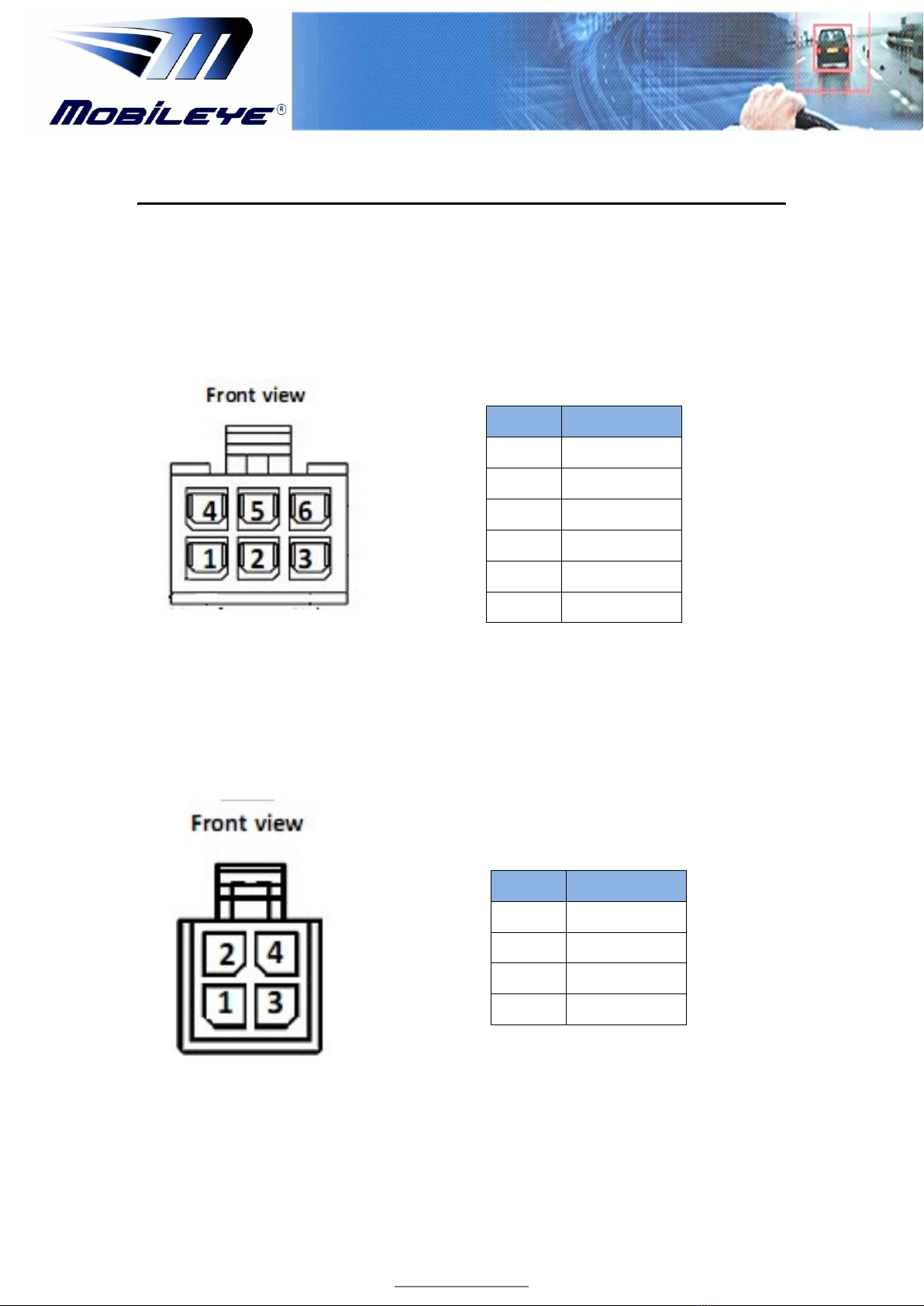
6EyeCAN / LOG Y-Cable Connectors (CAB000091) ............................................ 5
6.1 CAN channel 6 pin connector .........................................................................5
6.2 CAN channel 4 pin connector .........................................................................5
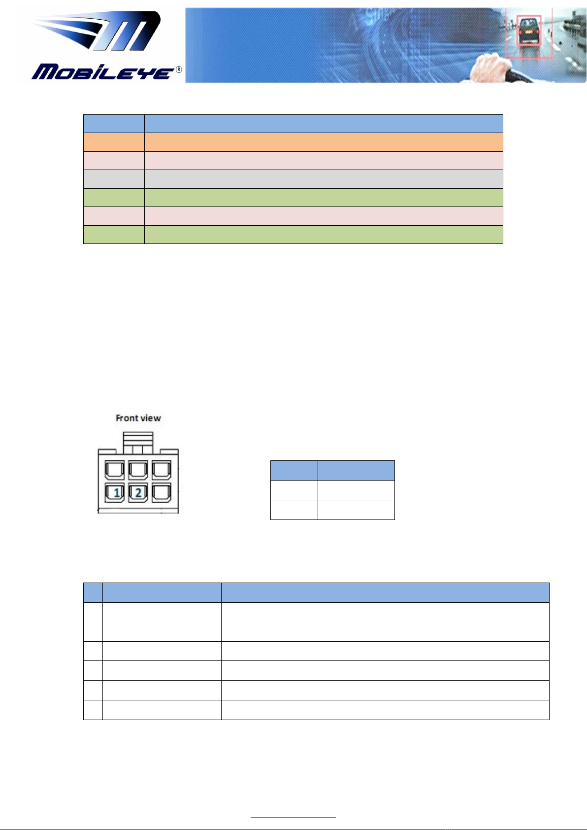
7EyeCAN Sniffer cable (CAB000092)................................................................. 6
7.1 EyeCAN Sniffer Cable (OBDII) .........................................................................6
7.2 OBDII connector .............................................................................................6
7.3 CAN Sniffing cable - 6 pin connectors ............................................................7
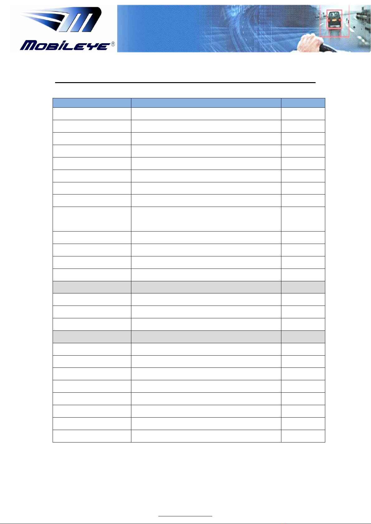
8Technical Data............................................................................................... 8
9Troubleshooting ............................................................................................ 9
9.1 EyeCAN cable is not functional ......................................................................9
9.1.1 Possible solutions #1 ..................................................................................9
9.1.2 Possible solution #2....................................................................................9
9.1.3 Checking EyeCAN Drivers ...........................................................................9
9.1.4 EyeCAN Drivers installation......................................................................10
9.1.5 EyeCAN Drivers Language malfunction ...................................................10
10 Connection Schemes ....................................................................................12
10.1 Mobileye C2-270 Connection Scheme with EyeCAN Cable ..........................12
10.2 EyeCAN cable with CAN Sniffer cable ..........................................................13
10.3 EyeCAN box ..................................................................................................14

3
Mobileye Vision Technologies
www.mobileye.com
1 Introduction
The EyeCAN cable is a one channel USB interface for CAN bus. It is used for installation and
calibration of Mobileye systems, as well as CAN-bus analysis purposes (sniffing) and Mobileye
firmware upgrades.
The EyeCAN uses USB 2.0 and handles messages with 11-bit (CAN 2.0A) and 29-bit (CAN
2.0B) identifiers. The EyeCAN can transmit* and receive remote frames.
The Mobileye EyeCAN also has the following features:
EyeCAN is a reliable low cost product developed and manufactured by Mobileye.
The EyeCAN supports full speed USB interface for CAN with high performance.
Loss free transmission and reception of standard and extended CAN messages on
the CAN bus is transmitted with a time stamp precision of 100 microseconds.
The low current consumption, 70 mA, reduces the power drain from your laptop.
Application Areas: Mobileye Setup Wizard (from v2.1.7), CANsee (from v1.8), AM
QC Application (from v2.8)
2 Device Components
The Mobileye EyeCAN cable kit is composed of 3 components:
1 - The EyeCAN USB cable
2 - EyeCAN / LOG Y-cable (CAB000091)
3 - EyeCAN Sniffer Cable (CAB000092)
123
Items 1 and 2 are used for Mobileye system Calibration and updating Firmware versions (using
the AM QC Application).
Item 1 and 3 are used for CAN sniffing (using the CANsee application).
More detailed information can be found in the chapters ahead and in the connections schemes
in chapter 10.
* EyeCAN does not transmit CAN messages to the vehicle CAN bus in Silent mode (default)

4
Mobileye Vision Technologies
www.mobileye.com
3 Power
The EyeCAN is powered through the USB connector. The host must supply 5V DC, as per
the USB specification.
4 LEDs
The EyeCAN has four LEDs. Their functions are shown in Table 1.
LED
LED Color
Function
Description
ERR
Red
ERR
PWR
Green
Power
Active when the EyeCAN is powered
LED 1
Blue
CAN Tx
Active when a CAN message is sent
from EyeCAN to CAN bus
LED 2
Yellow
CAN Rx
Active when a bulk of CAN messages
are sent from EyeCAN to USB bus
Table 1: EyeCAN LED configuration
5 USB connector
The EyeCAN may be connected to any free USB socket on the host computer. Power does
not have to be turned off before inserting or removing the device. It is good practice,
though, to exit all applications using the CAN hardware before removing the EyeCAN.
The USB cable included with the delivery is approx. 140 centimeters long and is
permanently attached to the EyeCAN. If a longer cable is desired, use a standard extension
cable with a type ―A‖ receptacle (Figure 4) at one end and a type ―A‖ plug (Figure 5) at
the other end. Do not extend the cable to more than 5 meters without an active extender.
With an active extender, the maximum length is 25 meters.
Figure 4: USB Type “A” Receptacle Figure 5: USB Type "A" Plug

5
Mobileye Vision Technologies
www.mobileye.com
6 EyeCAN / LOG Y-Cable Connectors (CAB000091)
In the “EyeCAN / LOG Y-cable”, the CAN channel is available via 2 connectors, one 4 pin
and one 6 pin (see image 2 in chapter 2 above).
The connecters pin layout is described in Table 2 and Table 3 below.
6.1 CAN channel 6 pin connector
Connecter type is: Neltron, P/N: 5560-06, Pin P/N: 5560T-LF
Figure 6: CAN channel 6 Pin Connector Table 2:
6.2 CAN channel 4 pin connector
Connecter type is: Molex, P/N: 43025-0400, Pin P/N: 43030-0003
Table: 3
Figure 7: CAN channel 4 Pin Connector
Pin
Function
Pin 1
CAN High
Pin 2
CAN Low
Pin 3
GND
Pin 4
Ignition
Pin 5
+5Vdc
Pin 6
+12Vdc
Pin
Function
Pin 1
CAN High
Pin 2
CAN Low
Pin 3
GND
Pin 4
Ignition

6
Mobileye Vision Technologies
www.mobileye.com
7 EyeCAN Sniffer cable (CAB000092)
7.1 EyeCAN Sniffer Cable (OBDII)
The EyeCAN Sniffer cable (CAB000092) is an additional cable Mobileye provides for CAN
Sniffing proposes. The cable is equipped with a multipurpose OBDII connector to allow a
quick connection to the vehicle’s OBDII connector and a connection to the vehicle’s CAN
interface for the following CAN-bus options:
Pins 6 and 14
Pins 3 and 11
Pin 1 (GMLAN)
The cable also has 2 free CAN cables to allow connection to vehicle’s CAN-bus wires which
are not in the OBDII connector:
White cable –CAN_H
Yellow cable –CAN_L
These cables are routed to the 6 pin Nelron connecter labeled (A 6H14L CAN A H L).
Figure 8: EyeCAN sniffer cable
7.2 OBDII connector
Figure 9: OBDII Male Connector, pin numbers

7
Mobileye Vision Technologies
www.mobileye.com
Table 4: OBDII pin configuration (showing only connected pins).
7.3 CAN Sniffing cable - 6 pin connectors
The 3 connectors in the CAN sniffing cable are leads from the relevant OBDII
pins
Figure 10: EyeCAN sniffer cable Table 5:
Table 6: CAN Sniffer cable 6 Pin Nelron connecters configurations
OBDII Pin
Function
1
GM LAN
3
CAN_H
4
Chassis Ground
6
CAN_H
11
CAN_L
14
CAN_L
Pin
Function
Pin 1
CAN High
Pin 2
CAN Low
#
Connector Label
Function
1
A 6H14L
CAN A H L
Transmit OBDII pins 6 (CAN High )and 14 (CAN Low)
Transmit messages from CAN High (White) and CAN Low (Yellow) cables
2
B 3H11L
Transmit OBDII pins 3 (CAN High )and 11 (CAN Low)
3
C 1H4G
Transmit OBDII pins 1 (GMLAN CAN High ) and 4 (GND via 10K resistor)
4
CAN A H (White cable)
Transmit messages from CAN High (White) cable via Connector #1
5
CAN A L (Yellow cable)
Transmit messages from CAN Low (White) cable via Connector #1

8
Mobileye Vision Technologies
www.mobileye.com
8 Technical Data
Property
Description
Unit
CAN channels
1 (CAN 2.0A and 2.0B active)
Error frame detection
Yes
Hardware requirements
IBM PC AT or 100% compatible; USB host socket
USB interface
USB 2.0
Power consumption
5V and approx. 70mA powered from the USB host
Software requirements
Windows XP, 7
Configuration
Done by software (Plug & Play)
Mix 11 / 29 bits messages
Yes
CAN Connector
6 pin Molex
4 Pin Molex
USB cable length
140 cm (approx. 4.6 ft.)
USB connector
USB standard type “A” plug
CAN cable length
30 cm (1 ft.)
Load dump protection
Yes (on USB)
Dimensions (W*L*H)
60.5mm X 91mm X 27 mm (Black plastic housing only)
Housing
Black plastic
Weight
120 gram
CAN physical layer
High speed (ISO 11898-2)
CAN transceiver
Texas SN65HVD234
USB speed
12
Mbit/s
Bit rate
5-500
Kbit/s
Temperature range
-0 - +70
Celsius°
Clock accuracy
100
µs
Max message rate
4000
Messages/s
Time stamp
32
Bits

9
Mobileye Vision Technologies
www.mobileye.com
9 Troubleshooting
9.1 EyeCAN cable is not functional
If there is no communication between the relevant software and the CAN-bus
system when connected with the EyeCAN please check the following:
a –Check all Cables, Connectors and Connections
b –Check USB connection (laptop side)
c –Check EyeCAN Drivers are installed correctly
9.1.1 Possible solutions #1
a –Close all applications using CAN-bus
b –Disconnect EyeCAN USB connector from computer
c –Reconnect EyeCAN USB connector to computer
After reconnection check the following:
d - Correct USB connection sound
e –EyeCAN Green Power Indication LED is On
f –Activate relevant application and try connection again
9.1.2 Possible solution #2
a –Close all applications using CAN-bus
b –Disconnect EyeCAN USB connector from computer
c –Restart computer
d –Reconnect EyeCAN USB connector to computer
After reconnection check the following:
e - Correct USB connection sound
f –EyeCAN Green Power Indication LED is On
g –Activate relevant application and try connection again
9.1.3 Checking EyeCAN Drivers
Check if the EyeCAN Drivers are installed correctly by performing the following:
a - Connect EyeCAN USB connector to computer
b –Right Click on “My Computer” and go to > Manage > Device Manager >
Universal Serial Bus controllers >
c –Check the following is installed correctly: “USB Bulk driver” (see figure)

10
Mobileye Vision Technologies
www.mobileye.com
Figure 11: Checking EyeCAN Drivers in Windows Device Manager
9.1.4 EyeCAN Drivers installation
The EyeCAN Drivers are installed automatically with the installation of the
Mobileye Setup Wizard. If the EyeCAN Drivers were not installed during the
Mobileye Setup Wizard installation or require a new installation perform the
following:
a –Download the EyeCAN Driver from this link
b –Run the EyeCAN Driver installation
c –When the Driver installation is complete connect the EyeCAN cable to computer
d –Perform checks as mentioned in the sections above
9.1.5 EyeCAN Drivers Language malfunction
If you get an error as in the below image and the Eye CAN driver installation stops,
and there is no communication between the System and laptop - (you will receive
OTP error) follow this steps:
Figure 12: Checking EyeCAN Drivers in Windows Device Manager

11
Mobileye Vision Technologies
www.mobileye.com
1 –Download the folder: “Bin_x86.rar”from this link to your Desktop and extract
the folder to your Desktop
2 –Right click on “Computer” and choose “Properties”
3 –Choose “device manager”
4 –Connect the EyeCAN cable to the Laptop USB port
5 –Click on “Universal Serial Bus controllers”
6 - Right on “USB Bulk driver”
7 –Choose “Update driver software”
8 –Choose “browse my computer for driver software"
9 - Browse and choose the "Bin_x86" folder you downloaded to your desktop
10 –Click “NEXT” for Driver update to take place

12
Mobileye Vision Technologies
www.mobileye.com
10 Connection Schemes
10.1 Mobileye C2-270 Connection Scheme with EyeCAN Cable
Figure 13: Mobileye C2-270 connections scheme with EyeCAN Cable

13
Mobileye Vision Technologies
www.mobileye.com
10.2 EyeCAN cable with CAN Sniffer cable
Figure 14: EyeCAN Cable with CAN Sniffer cable

14
Mobileye Vision Technologies
www.mobileye.com
10.3EyeCAN box
Figure 15: EyeCAN permanent USB cable connection Figure 16: EyeCAN CAN connector and ELD’s
Figure 15:
The “RS485” connector is currently not in use and is intended for future purposes.
Do not connect!!!
The “SD CARD” slot is currently not in use and is intended for future purposes
Figure 16:
The “CAN” connector is used for connection with the EyeCAN / LOG Y-cable
(CAB000091)
The LED’s functionality is described in Chapter 4.
Copyright 2011
Mobileye Vision Technologies
http://www.mobileye.com
Last updated Monday, June 6, 2011
This manual suits for next models
2
Table of contents