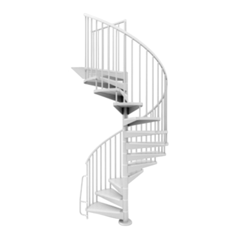
mobirolo MAGIC User manual

Code Magic_FX Rev 00 Edition 03/2017
advanced mobularstairsystem
Mod. MAGIC
MC
ISTRUZIONI DI MONTAGGIO
ASSEMBLY INSTRUCTIONS
NOTI CE DE M ON TAGE
MONTAGEANLEITUNGEN
INSTRUCCIONES DE MONTAJE

Via C.Colombo, 22/A - 42046 - Reggiolo - Reggio Emilia - Italy
Tel. +39 - 0522-211811 - Fax +39 - 0522-97 31 39
www.mobirolo.com mobirolo@mobirolo.it
Mobirolo S.p.A.
-2 - MAGIC
- MAGIC -
Prima diprocedere conle varie fasi dimontaggio, vuotareilcartonee posizionare tutti i particolari suuna superficie
piana,verificare la presenza ditutti icomponenti comeda distintaallegata, eche nonvi sianoparti danneggiate.
Rif. Dis. N. pz. Rif. Dis. N. pz.
L11Mag
L12Mag
210-0074B
B16
PARTE 1; PART 1; PARTIE 1; TEIL 1; PARTE 1
COMPONENTI; COMPONENTS; COMPOSANTS; BAUTEILE; COMPONENTES
Before proceeding to the various assembly stages, empty the cardboard package andarrange all parts ona flat
surface to check that all components included in the list attached are present, and that no damaged parts are
present.
Avantde procéderauxdifférentes phases demontage, retirer tous les éléments ducarton etles disposer sur une
surfaceplane. Contrôlerque tousles composantssont présentsense référant àliste d’accompagnementet vérifier
qu’aucunélément nesoit endommagé.
Vor Beginnder verschiedenenMontagephasen, denKartonentleeren, alle Teile auf eineebene Flächelegen und
prüfen, dassalle Bauteilelaut beiliegenderStückliste vorhandensind, dassdie Mengeder TeiledenAngabeninder
beiliegendenStückliste entsprichtund dasskeine Teile beschädigt sind.
Antes de empezar con las diferentes fases del montaje, vacíe la caja y coloque todos los elementos sobre una
superficie plana, compruebe que estántodos los componentes que se indicanen la lista adjunta y que no haya
partes dañadas.

Via C.Colombo, 22/A - 42046 - Reggiolo - Reggio Emilia - Italy
Tel. +39 - 0522-211811 - Fax +39 - 0522-97 31 39
www.mobirolo.com mobirolo@mobirolo.it
Mobirolo S.p.A.
-3 -
MAGIC
- MAGIC -
Rif. Dis. N. pz.
K1
1080 - 510- 170
Ø60
K4
K5
300
M20
K7
K6
Rif. Dis. N. pz.
K15
K2A L. 510 mm
K2B L. 170 mm
K2C L. 1080 mm
M10
M20
K63L
K16
M10x70
COMPONENTI; COMPONENTS; COMPOSANTS; BAUTEILE; COMPONENTES
210-0051
K18
M72
1360 mm
Ø22 mm
x 7
K60
K84 Lungh.6500 mm
x 16
998-0043 x 5

Via C.Colombo, 22/A - 42046 - Reggiolo - Reggio Emilia - Italy
Tel. +39 - 0522-211811 - Fax +39 - 0522-97 31 39
www.mobirolo.com mobirolo@mobirolo.it
Mobirolo S.p.A.
-4 - MAGIC
- MAGIC -
Rif. Dis. N. pz. Rif. Dis. N. pz.
K51
K45
K49 Ø127
146
K50 Ø127
156
K58
K44
K81
210-0077 x 3
x 25
P110
B203

Via C.Colombo, 22/A - 42046 - Reggiolo - Reggio Emilia - Italy
Tel. +39 - 0522-211811 - Fax +39 - 0522-97 31 39
www.mobirolo.com mobirolo@mobirolo.it
Mobirolo S.p.A.
-5 -
MAGIC
- MAGIC -

Via C.Colombo, 22/A - 42046 - Reggiolo - Reggio Emilia - Italy
Tel. +39 - 0522-211811 - Fax +39 - 0522-97 31 39
www.mobirolo.com mobirolo@mobirolo.it
Mobirolo S.p.A.
-6 - MAGIC
- MAGIC -
IMPOSTAZIONE
Per uncorretto montaggio della scala,occorre impostare esattamenteil numerodei gradini, la loroalzata “A” e la
partenza, inmodo da arrivare algradinosbarco rispettando l’esatta posizione.
Nelle Figure (fig.a- fig.b)vengono schematizzate alcune composizioni.
A-alzata gradino
H - altezza scala
PARTE 2; PART 2; PARTIE 2; TEIL 2; PARTE 2
SET-UP
To assemble thestaircase correctly,the precise number ofsteps, their“A” riseandstartingpoint must be identified
so as to place the finaltop step in thecorrect position.
Some set-ups are reported (fig.a –fig. b).
A–step rise
H–staircase height
CONFIGURATION
Pour bien monter l’escalier, il faut déterminer le nombre exact des marches, la hauteur de marche Aet celle de la
marche départ, de façonque l’arrivée sur lamarche palière respecte labonne position.
présente(fig.a -fig.b) illustre quelques compositions.
A- hauteurentre deuxmarches consécutives
H- hauteur sol à sol
EINSTELLUNG
Für eine korrekte Treppenmontageist dieZahl derStufen, sowie deren Steigung“A” undAntritt genauzu
bestimmen, um an derAustrittstufe in der richtigen Position zuenden.
Auf dieser Seite(Abb.a-Abb.b) werden einige Treppengestaltungenschematisch dargestellt.
A- Steigung
H-Treppenhöhe
COLOCACIÓN
Para uncorrecto montajede laescalera, establezcaexactamente elnúmero depeldaños, sucontrahuella “A” y la
partida, demodo quese llegueal peldañode desembarque respetando laposiciónexacta.
Enesta página, (fig.a-fig.b)se esquematizanalgunas composiciones.
A- contrahuelladel peldaño
H-altura de la escalera

Via C.Colombo, 22/A - 42046 - Reggiolo - Reggio Emilia - Italy
Tel. +39 - 0522-211811 - Fax +39 - 0522-97 31 39
www.mobirolo.com mobirolo@mobirolo.it
Mobirolo S.p.A.
-7 -
MAGIC
- MAGIC -
Øforo
ØS
A
H
Fig.a
Fig.b
Ø S 1200
DX SX

Via C.Colombo, 22/A - 42046 - Reggiolo - Reggio Emilia - Italy
Tel. +39 - 0522-211811 - Fax +39 - 0522-97 31 39
www.mobirolo.com mobirolo@mobirolo.it
Mobirolo S.p.A.
-8 - MAGIC
- MAGIC -
Colonna “H” Valore dell’altezza rilevatada impostare.
Colonna “G” Numerodei gradini da montare.
Sezione “P” Composta da tre colonne riguardanti la lunghezza ed ilnumero dei pali da utilizzare.
Inesse sideve rilevareil numero di pezzi da montare.
Sezione “A” Composta da sei colonne riguardanti ilvalore di alzata.
Nelle caselle,sotto ognicolonna, vengonovisualizzate quantealzate si devono realizzare.
Nelle sei colonne,inoltre, sono indicati quanti distanziali occorre montare perrealizzare la
rispettivaalzata.
Nell’esempiosotto riportato,si è impostato unvalore dialtezza “H”pari a2805 mm.
Nella colonna “G” viene indicato che occorre utilizzare tredici gradini.
Nella sezione “P” sirileva che devonoessere montati duepali K2C dilungh. 1080 mmed uno K2A di 510 mm.
USO DELLA TABELLA “A”
La Tabella “A”è unsistema parametrico necessario perdeterminare ilnumero dialcuni componenti della scala:
Componenti del palo numero gradini numero dei distanziali per ogni alzata
Nella sezione “A” si rilevanoi seguentiparametri:
N° 10 Gradini con alzate “A” da 215 mm, con 4 distanziali K45.
N° 2 Gradini con Alzate “A” da 220 mm, con 5 distanziali K45.
Fig.1
H
RILIEVO ALTEZZA UTILE
Rilevare lamisura dell’altezzada pavimentosuperiore a
pavimentoinferiore “H”.(Fig.1)
USEFUL HEIGHT MEASUREMENT
Measure the “H” height fromthe topceilingtothe bottom
floor. (Fig. 1)
MESURE DE LA HAUTEUR UTILE
Mesurer la hauteur entre le plancher supérieur et le
plancherinférieur H. (Fig. 1)
MESURE DE LA HAUTEUR UTILE
Mesurer la hauteur entre le plancher supérieur et le
plancher inférieur H. (Fig. 1)
DETERMINACIÓN DE LA ALTURA ÚTIL
Determine la distancia del pavimento superior al
pavimento inferior, “H”. (fig.1)

Via C.Colombo, 22/A - 42046 - Reggiolo - Reggio Emilia - Italy
Tel. +39 - 0522-211811 - Fax +39 - 0522-97 31 39
www.mobirolo.com mobirolo@mobirolo.it
Mobirolo S.p.A.
-9 -
MAGIC
- MAGIC -
Column“H” Value of the measured rise to be set
Column “G” Number of steps to be mounted.
Section “P” Includingthree columns relating to the length and the number of piles to be used.
The number of parts to be assembledmust bederivedfromthereferences above.
Section“A” Composed ofsix columns relatingto the rise value.
Inthe example reported below,a “H”height value was set amountingto2805 mm.
The column “G” shows thatthirteen stepsare necessary.
The section “P” shows that two 1080 mmlong K2C piles and one 510 mm long K2A pile must be mounted.
USING THE TABLE “A”
TheTABLE “A”is aparametric systemnecessary tocalculate the number of certain componentsof the
staircase:
Pile components step number number of spacers for each rise
Section “A” shows thefollowingparameters:
N. 10 steps with 215 mm “A” rises with 4 K45
N. 2 steps with 220 mm“A” rises with 5 K45
Colonne “H” Mesure dela hauteurà configurer.
Colonne “G” Nombre de marchesà monter.
Section“P” Elle estcomposée detrois colonnes et concerne la longueuret laréférence des éléments du mât à
utiliser. Ces colonnes permettent d’établirle nombrede pièces à monter.
Section“A” Elle est composée desix colonnes et concerne la valeurde hauteurde marche.
Les cases sous chaque colonne reportent le nombrede hauteursde marcheà réaliser.
Dans l’exemplereporté ci-dessous, lavaleur de lahauteur “H”configurée estde 2805mm.
La colonne “G” indique qu’ilfaut utiliser treize marches.
La section “P” indique qu’ilfaut monter deux éléments dumât K2C de1080 mmde longet unélément K2A de 510
mm de long.
UTILISATION DE LA TABLEAU “A”
La TABLEAU“A”est unsystème paramétriquenécessaire pour déterminer lenombre de certains composants
de l’escalier:
Composants du mât nombre de marches
nombredes bagues intermédiaires pour chaque hauteurde marche
La section “A” indique les paramètres suivants:
10 Marches avec hauteur “A” de 215 mm, avec4 bagues intermédiaires K45
2 Marches avec hauteur “A” de 220mm, avec 4 bagues intermédiaires K45

Via C.Colombo, 22/A - 42046 - Reggiolo - Reggio Emilia - Italy
Tel. +39 - 0522-211811 - Fax +39 - 0522-97 31 39
www.mobirolo.com mobirolo@mobirolo.it
Mobirolo S.p.A.
-10 - MAGIC
- MAGIC -
Spalte “H” Gemessener,einzustellender Höhenwert.
Spalte “G” Anzahl der zu montierendenStufen.
Abschnitt “P” Bestehendaus drei Spalten,welche die Länge und den Bezugspunkt der zu
verwendendenPfosten betreffen.
Hier ist dieAnzahlder zumontierenden Teile zuentnehmen.
Abschnitt “A” Bestehend aus sechs Spalten,die denSteigungswert betreffen.
In denKästchenunterjeder Spalte ist angeführt,wie vieleSteigungenzufertigensind.
Imunten stehendenBeispielwurdeein Höhenwert “H” von 2805 mm eingestellt.
Die Spalte “G” gibt an, dass dreizehnStufen verwendetwerden müssen.
DerAbschnitt “P” gibt an, dass zwei SäulenK2C Länge 1080 mmundeine K2ALänge 510mmzumontieren sind.
GEBRAUCH DES TABELLE “A”
Der TABELLE“A” ist einParametersystem, das zurBestimmungderAnzahleiniger Treppenbauteile
erforderlich ist:
Bauteile der Säule Anzahlder Stufen Anzahl der Distanzstücke pro Steigung
DerAbschnitt “A” liefert die folgenden Parameter:
10 St. Stufen mit Steigung “A” von 215 mm, mit 4 Distanzstücken K45.
2 St. Stufen mit Steigung“A” von 220 mm, mit 5 Distanzstücken K45.
Columna “H” Valorde laaltura determinada a establecer.
Columna “G” Número de peldañosque hay que montar.
Sección “P” Compuesta por tres columnas relacionadas con la longitud y lareferencia de los postes a utilizar.
Enéstas se debe determinar elnúmero de piezas que se vana montar.
Sección “A” Compuesta por seis columnas relacionadas con elvalor de la contrahuella.
Enlas celdas, bajo cada columna, sevisualiza cuántas contrahuellas hay que realizar.
Enel ejemplo que se da a continuación, se ha establecido unvalor de altura “H” de2805 mm.
Enla columna “G” se indica que es necesario utilizar trece peldaños.
Enla sección “P” se indica que hay que montar dos postes K2C de long. 1080 mmy uno K2Ade 510 mm.
USO DEL TABLA “A”
“TABLA“A” es unsistema paramétrico necesariopara determinarel númerode algunoscomponentes dela escalera
Componentes del poste Número de escalones número deespaciadores porcada contrahuella
Enla sección“A” se dan los siguientes parámetros:
10 peldaños con contrahuellas “A” de 215 mm, con 4 espaciadores K45
2 peldaños con contrahuellas “A” de 220 mm, con5 espaciadores K45
K2C K2A K2B

Via C.Colombo, 22/A - 42046 - Reggiolo - Reggio Emilia - Italy
Tel. +39 - 0522-211811 - Fax +39 - 0522-97 31 39
www.mobirolo.com mobirolo@mobirolo.it
Mobirolo S.p.A.
-11 -
MAGIC
- MAGIC -

Via C.Colombo, 22/A - 42046 - Reggiolo - Reggio Emilia - Italy
Tel. +39 - 0522-211811 - Fax +39 - 0522-97 31 39
www.mobirolo.com mobirolo@mobirolo.it
Mobirolo S.p.A.
-12 - MAGIC
- MAGIC -

Via C.Colombo, 22/A - 42046 - Reggiolo - Reggio Emilia - Italy
Tel. +39 - 0522-211811 - Fax +39 - 0522-97 31 39
www.mobirolo.com mobirolo@mobirolo.it
Mobirolo S.p.A.
-13 -
MAGIC
- MAGIC -

Via C.Colombo, 22/A - 42046 - Reggiolo - Reggio Emilia - Italy
Tel. +39 - 0522-211811 - Fax +39 - 0522-97 31 39
www.mobirolo.com mobirolo@mobirolo.it
Mobirolo S.p.A.
-14 - MAGIC
- MAGIC -
Fig.3
TRACCIATURA
Trovareeproiettareaterrailcentro scala.Come indicato
infig.2 e fig.3.
K1
Ø12
Fig.4
Fig.2
Fig.4a
Fig.4b
K6
K7
Procedere poicome illustratoin Fig. 4- 4a - 4b
TRACING
Finda and project the centre of the stairwall staircase
as shownin Fig.2 - Fig. 3
Then proceedas shownin Fig4- 4a - 4b
TRACÉ
Déterminer et projeter au sol le centre de l’escalier.
Commeindiqué fig.2e fig.3.
Ensuite, procédezcomme indiqué à la figure 4 - 4 - 4b
MARKIERUNG
Den Mittelpunkt des Treppenhauses ausfindig machen
undaufdenBodenübertragen. wie inderAbb.2-Abb.3
gezeigt.
Dann gehenSie wie inAbb. 4 -4a - 4b
TRAZADO
Encuentre elcentro de escaleray proyéctelohacia el
suelo. Como se indica enla fig. 2 - Fig.3
Acontinuación,proceder como se muestra en la Fig. 4 - 4 - 4 ter

Via C.Colombo, 22/A - 42046 - Reggiolo - Reggio Emilia - Italy
Tel. +39 - 0522-211811 - Fax +39 - 0522-97 31 39
www.mobirolo.com mobirolo@mobirolo.it
Mobirolo S.p.A.
-15 -
MAGIC
- MAGIC -
INDIVIDUAZIONE N° GRADINI
Consultando TabellaAconmisura “H” inmm, vengono indicati il
numero di elementi percomporre il palo “P”.
Es. sempre per un’altezza di 2805, dovranno essere utilizzati
n°2elementi da1080 en°1 elementoda 510.
Comporre ilpalo come illustrato in fig. 5. Iniziare ad avvitare a
fondo ilprimo componente di palo K2 (A-B-C)nella flangia K1.
Attenzionea nonrovinareilfiletto durantel’operazione. Montare
lo spezzone K2 (A-B-C) che comporràil palo.
Fig.5
K2
CALCULATING THE NUMBER OF STEPS
By consultingthe Table “A” set at the “H” measure in mm, the
number of elements is shown to composethe pile “P”.
NB. in the case of a 2805 mm height, n. 2 1080 mm elements
andone 510 mmelement are needed.
Composethepostas shownin fig.5. Start tighteningthe first K2
(A-B-C) pilecomponent withthe K1 flange.Avoiddamagingthe
thread duringthe operation. Mountthe K2(A-B-C) segment that
willcompose the pile.
DÉTERMINATION DU NOMBRE D’ÉLÉMENTS DU MÂT CENTRAL
Consulter la TABLEAU“A” de mesure.H. enmm qui indique le nombre d’éléments pour composer le mât.P..
Ex:toujours pour une hauteurde 2805, ilfaudra utiliser 2 éléments de 1080 et 1 élémentde 510.
Monter le mât comme illustré fig. 5. Commencer par visser à fond lepremier élémentdumât K2 (A-B-C) ausabot
K1.Avoirsoinde ne pasendommagerlefiletage pendant cetteopération.Monterl’élément K2(A-B-C) quiconstituera
le mât.
BESTIMMUNG DER STUFENZAHL
Durch Tabelle “A” des mm-Maßes “H” auf demRechenschieber ergibt sich die ZahlderElemente, ausdenender
mittlere Spindelmast “P” besteht.
Beisp.: Bei einer Höhe von2805 mmsind2 St. Elemente 1080 und1 St.Element 510zu verwenden.
Den Spindelmast wie inderAbb. 5 dargestellt zusammenbauen. Denersten Mastbestandteil K2 (A-B-C) fest am
Flansch K1 anschrauben. Achtung! Das Gewindedabei nicht beschädigen. DenAbschnitt K2 (A-BC)montieren,
der den Spindelmast zusammensetzen wird.
K1
DETERMINACIÓN DEL NÚMERO DE PELDAÑOS
Consultando el Tabla “A” conmedida “H” en mm, aparece indicado el número de elementos para componer el
poste “P”.
Por ejemplo, siempre para una altura de 2805mm, sedeberán utilizar 2 elementos de1080 mmy 1 elemento de
510 mm.
Componga el poste como se ilustra en la fig. 5. Empiece a atornillara fondoel primercomponente delposte, K2
(A-B-C) alabrida K1.Tenga cuidado para no estropearlaroscadurantelaoperación.Montare la secciónK2(A-B-
C)que compondrá el poste.

Via C.Colombo, 22/A - 42046 - Reggiolo - Reggio Emilia - Italy
Tel. +39 - 0522-211811 - Fax +39 - 0522-97 31 39
www.mobirolo.com mobirolo@mobirolo.it
Mobirolo S.p.A.
-16 - MAGIC
- MAGIC -
MAGIC = DX
Fig. 6a
DX
Fig. 6b

Via C.Colombo, 22/A - 42046 - Reggiolo - Reggio Emilia - Italy
Tel. +39 - 0522-211811 - Fax +39 - 0522-97 31 39
www.mobirolo.com mobirolo@mobirolo.it
Mobirolo S.p.A.
-17 -
MAGIC
- MAGIC -
MAGIC = DX DX
30 mm
Fig. 6c
Fig. 6d
Fig. 6e

Via C.Colombo, 22/A - 42046 - Reggiolo - Reggio Emilia - Italy
Tel. +39 - 0522-211811 - Fax +39 - 0522-97 31 39
www.mobirolo.com mobirolo@mobirolo.it
Mobirolo S.p.A.
-18 - MAGIC
- MAGIC -
SX
MAGIC = SX
Fig. 6a
Fig. 6b
SX

Via C.Colombo, 22/A - 42046 - Reggiolo - Reggio Emilia - Italy
Tel. +39 - 0522-211811 - Fax +39 - 0522-97 31 39
www.mobirolo.com mobirolo@mobirolo.it
Mobirolo S.p.A.
-19 -
MAGIC
- MAGIC -
MAGIC = SX
Fig. 6c
Fig. 6d
Fig. 6e
SX
30 mm

Via C.Colombo, 22/A - 42046 - Reggiolo - Reggio Emilia - Italy
Tel. +39 - 0522-211811 - Fax +39 - 0522-97 31 39
www.mobirolo.com mobirolo@mobirolo.it
Mobirolo S.p.A.
-20 - MAGIC
- MAGIC -
MAGIC = DX
DX
Other mobirolo Indoor Furnishing manuals