2
TABLE OF CONTENTS
TOOL LIST …………………………………………………………………………...3
PARTS LIST …………………………………………………………………………...4
SAFETY …………………………………………………………………………...6
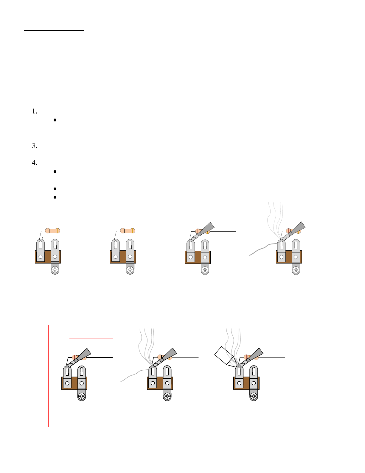
SOLDERING TIPS …………………………………………………………………...7
WIRING TIPS ……………………………………………...................................8
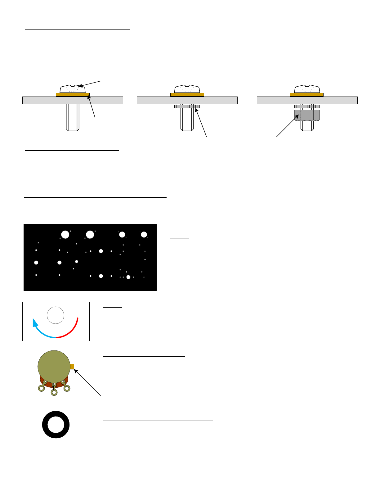
HARDWARE FASTENING TIP …………………………………………………...9
STEP BY STEP ASSEMBLY INSTRUCTIONS …………………………………...9
Section 1 – Mounting of Top Components …………………………………...9
Section 2 – Mounting of Front Components ………………………………….12
Section 3 – Mounting of Rear Components ………………………………….13
Section 4 – Mounting Internal Terminal Strips and Passive Components ….14
Section 5 – Solder the Filter Components ………………………………….16
Section 6 – Connect the Front Mounted Components ………………….18
Section 7 – Connect TR2 to the Impedance Selector Switch ………………….20
Section 8 – Connect the Tube Sockets ………………………………….22
Section 9 – Connect the Terminal Strip Interconnects ………………….23
Section 10 – Connect the Tube Filaments ………………………………….23
Section 11 – Insert the Strain Relief and Connect the Power Cord ………….24
Section 12 – Fasten the Rubber Feet to the Chassis Cover ………………….25
Section 13 – Fasten the Chassis Cover to the Chassis Box ………………….25
Section 14 – Set the Bias of the Power Tubes ………………………….26
Section 15 – Fasten the Steel Cage to the Chassis Box ………………….28
Section 16 – Modifications ………………………………………………….29
PARTS LIST DRAWINGS (4)
There are four parts list drawings separated from these instructions to help you find
each part and identify it.
ASSEMBLY DRAWINGS (25)
There are 25 assembly drawings separated from these instructions to help you with each
step of the assembly.