Mod MOD 102 User manual

1Copyright © 2014 by modkitsdiy.com
Use these instructions to learn:
How to build a tube amp.
This tube guitar amplifier circuit is based on a classic American circuit design combined with a British style
class A output section. At low volume it produces a clean chimey tone that moves into smooth overdrive at
higher volumes.
MOD 102 GUITAR AMP KIT (K-MOD102-F)
VOLUME
0
1
2
3
456
7
8
9
10
TREBLE
0
1
2
3
456
7
8
9
10
ON
OFF
MOD 102
TUBE AMP KIT
BASS
0
1
2
3
456
7
8
9
10
®
The MOD102-F is the foreign (Non-USA) version of the MOD 102 including a Hammond 369EX
world power transformer instead of the 269EX. Please note: there is no power cord included with
this kit (due to variations in electrical outlets around the world). You will need to find a power cord
that can fit through the ¼" diameter (6.35 mm) rubber grommet hole on the rear panel.

2
TABLE OF CONTENTS
TOOL LIST …………………………………………………………………………...3
PARTS LIST …………………………………………………………………………...4
SAFETY …………………………………………………………………………...5
SOLDERING TIPS …………………………………………………………………...6
WIRING TIPS ……………………………………………...................................7
HARDWARE FASTENING TIP …………………………………………………...8
STEP BY STEP ASSEMBLY INSTRUCTIONS …………………………………...8
Section 1 - Mounting of Top Components …………………………………...8
Section 2 - Mounting of Front Components ………………………………….10
Section 3 - Mounting of Rear Components …………………………………..11
Section 4 - Mounting Internal Terminal Strips and Passive Components …….11
Section 5 - Connect Front Mounted Components …………………………….14
Section 6 - Connect Rear Mounted Components …………………………….14
Section 7 - Finish Connecting the Transformer and Power Supply Wires ……15
Section 8 - Connect the Tube Filament Wiring ……………………………….15
Section 9 - Finishing Up……………………………………………………… 16
Label Mounting Instructions ………………………………………………...17
PARTS LIST DRAWINGS (4)
There are four parts list drawings separated from these instructions to help you find and
identify each part.
ASSEMBLY DRAWINGS (9)
There are 9 assembly drawings and one Primary Wiring Diagrams page separated from
these instructions to help you with each step of the assembly.

MOD 102 GUITAR AMP KIT – BACKGROUND
The MOD 102 Guitar Amp Kit was designed for anyone who is interested in building their own tube guitar
amplifier head.
It is meant for practice amp volume (up to 5 Watts). It has an 8 ohm output impedance. (We recommend
using it with a speaker cabinet that has an overall power handling of at least 10W). Use 16 AWG speaker
cable to connect from the amplifier to your speaker cabinet.
The web-site www.modkitsdiy.com has been set up to help answer your questions after you have thoroughly
read through the entire set of instructions.
3
TOOL LIST
Wire Strippers
Needle Nose Pliers
Cutting Pliers
Desoldering Pump
Solder (60/40 rosin core)
Soldering Station
Phillips Head Screwdrivers
Slotted tip screwdrivers (3mm tip)
Digital Multimeter (DMM)
Alligator Clip Test Leads (to fit DMM)
Channellock Pliers (or similar type)
Miniature Round File (fine cut)

PARTS LIST
Please see the parts list drawings for help with finding and identifying each part
along with corresponding part numbers.
RESISTORS:
Description Quantity
100Ω 1W 1
200Ω 5W 1
1kΩ 1W 1
1.5kΩ 1/2W 2
5.6kΩ 1/2W 1
6.8kΩ 1/2W 1
22kΩ 1W 1
100kΩ 1/2W 3
220kΩ 1/2W 1
220kΩ 1W 1
1MΩ 1/2W 1
TERMINAL STRIPS:
Description Quantity
5 lug terminal strip (1st lug common) 3
5 lug terminal strip (3rd lug common) 1
7 lug terminal strip (1st & 7th lug common) 1
2 lug terminal strip (2nd lug common) 1
HARDWARE:
Description Quantity
#8 self-tap screws 4
#6 screws 9
#6 hex nuts 9
#6 lock washers 2
#4 screws 4
#4 hex nut 4
#10 screws 4
#10 hex nuts 4
#10 lock washers 4
TUBES:
Description Quantity
12AX7/ECC83 1
6BQ5/EL84 1
TRANSFORMERS:
Description Quantity
Power Transformer 369EX 1
Output Transformer P-T31 1
4
CAPACITORS:
Description Quantity
250pF 500V 1
.022µF 400V 1
.047µF 400V 1
.1µF 400V 1
22µF 50V 2
22µF 350V 2
47µF 350V 1
100µF 100V 1
MISCELLANEOUS PARTS:
Description Quantity
Solid state diode 1N4007 2
250kΩ audio pot 2
1MΩ audio pot 1
knobs 3
Input jack (switched) 1
output jack 1
9 pin miniature tube socket 2
preamp tube shield 1
EL84 tube retainer 1
Rubber Grommet (3/8" center) 4
Rubber Grommet (1/4" center) 1
violet jewel 1
Power switch (SPST) 1
1A fuse 1
Fuse holder 1
Light bulb 1
Lamp holder 1
Handle with mounting hardware 2
Rubber bumpers 4
Steel chassis box and cover 1/each
Labels 1 set
Green 20 AWG wire 4 feet
White 20 AWG wire 6 feet

5
DANGER
HIGH VOLTAGE
MAY BE PRESENT
ON FILTER CAPACITORS
DO NOT TOUCH!
SAFETY
Tube amps operate at high voltages that have the potential to injure and kill. Please remember the following
when working on this project.
Only work on the amp when you are wide awake and sober.
Do not plug the amp in until you have gone through all of the instructions, checking and re-checking
each step.
Do not turn the amp on until you have connected it to a speaker cabinet.
Be aware that tubes become very hot when the amp is on and can take up to 10 minutes to cool down
after power is turned off.
Work in a ventilated area when soldering.
Always follow the one hand rule when working with an amp that is connected to power or may have
voltage present. (Any amp that has been plugged in at one time, may have high voltage present).
ON STANDBY
The one hand rule (pictured below): is a safety precaution for working on an amp that is
plugged in or could potentially have high voltages present. Using alligator clips with your
DMM, clip the ground side to the chassis and use the other side to probe at various test points
with one hand. This prevents a fatal shock which can result from current passing through the
heart. (Many people even put their other hand in their pocket or behind their back).
Always probe the amp for dangerous voltages at several test points before working on it, even if it has been turned
off and unplugged for months.
Test points include:
Each positive end of polarized filter caps
Visit www.modkitsdiy.com if you have any problems when first turning on your amp for
troubleshooting help. If you smell or see smoke, hear something pop, or the chassis becomes too
hot to touch, turn off power and unplug immediately.

SOLDERING TIPS
1. Bend the component lead
and wrap it around the
connection point.
2. Wrap the component lead
so that it can hold itself to the
connection point.
3. Heat up both component
lead and connection point with
the soldering iron.
4. Apply solder to both
component lead and
connection point.
2. Apply fresh solder to mix in
with old solder joint
1. Heat up old solder joint
with the soldering iron.
3. Use a de-soldering tool to
remove the old solder joint
while it is heated.
De-Soldering Tip
6
It is important to make a good solder joint at each connection point. A cold solder joint is a connection that
may look connected but is actually disconnected or intermittently connected. (A cold solder joint can keep
your project from working.)
Follow these tips to make a good solder joint. Take your time with each connection and make sure that all
components are connected and will remain connected if your project is bumped or shaken.
Bend the component lead or wire ending and wrap it around the connection point.
Make sure it is not too close to a neighboring component which could cause an
unintended connection.
2. Wrap the component lead so that it can hold itself to the connection point.
Touch the soldering iron to both the component lead and the connection point allowing both to
warm up just before applying the solder to them.
Be sure to adequately cover both component lead and connection point with melted solder.
Remove the soldering iron from your work and allow the solder joint to cool. (The
solder joint should be shiny and smooth after solidifying.)
Cut off any excess wire or component leads with cutting pliers.
Clean the soldering iron's tip by wiping it across the wet sponge again after making the
solder joint.

WIRING TIPS
7
Because of the electro-magnetic
properties of current traveling through a
wire, there are wiring conventions used
when making wire connections.
A) Twist the wires together where
indicated in the instructions.
B) If two wire paths intersect, try to have
them cross over each other as
perpendicular as possible. (You should
follow the path of the wires shown in the
instructions).
Measure the wire by running it along its actual path (shown in the drawings) and then cutting it with
your wire cutters at a length that will give it a little bit of slack after stripping off the insulation and
soldering.
It is important not to make the wires too long.
Be careful not to burn the insulation of nearby wires with the soldering iron.
With the terminal strips used in this kit, you might want to connect some wires to the lower holes
and components to the upper holes. (Doing this can make it easier to change components for
modification).
5W 1K
5W 1K
Wires connected to lower terminal holes.
Components connected to upper terminal
holes.
1
2
3
4
5
6
7
8
9
1
2
3
4
5
6
7
8
9
A) Twisted Wires
B) Perpendicular
Intersection

STEP BY STEP ASSEMBLY
Please refer to the respective drawings for each section. We recommend browsing over the instructions and
looking at all drawings once before actually beginning to assemble the kit.
HARDWARE FASTENING TIP
When fastening components with mounting hardware (screws, lock washers, and hex nuts), the lock washer and
hex nuts should be fastened on the other side of the chassis from the head of the screw in the order pictured
below.
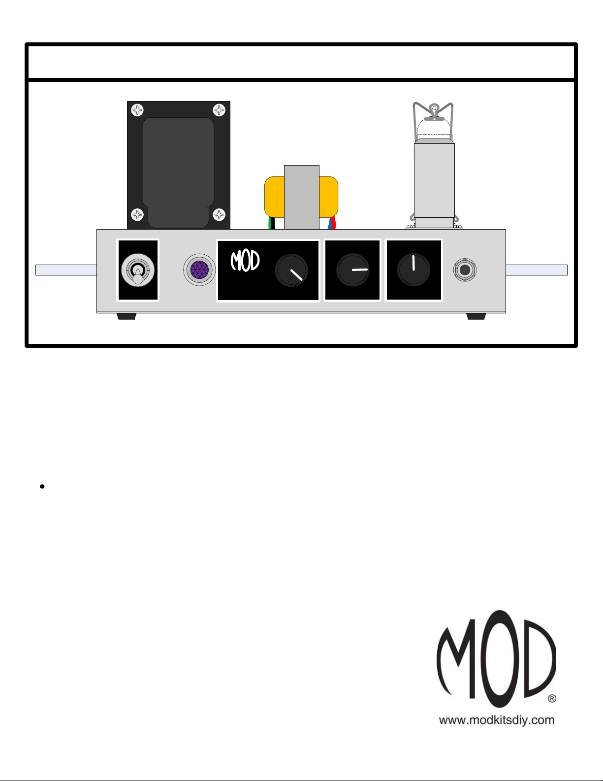
SECTION 1 – Mounting of Top Components
Please refer to Drawings 1 – 3. Find your chassis box. Drawing 1 identifies the names of
components that you will be mounting to the top of the chassis box.
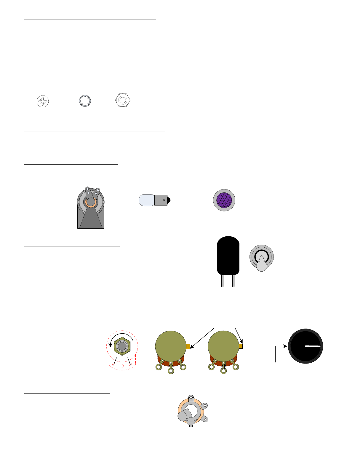
Step 2 – Mount the rubber grommets with the 3/8" centers
Drawing 2 shows where to mount these four rubber grommets. Squeeze the grommet into
the hole and push it into place with your fingers.
8
Chassis
Screw Head
Lock Washer Hex Nut
Component Mounting
Bracket
(4)
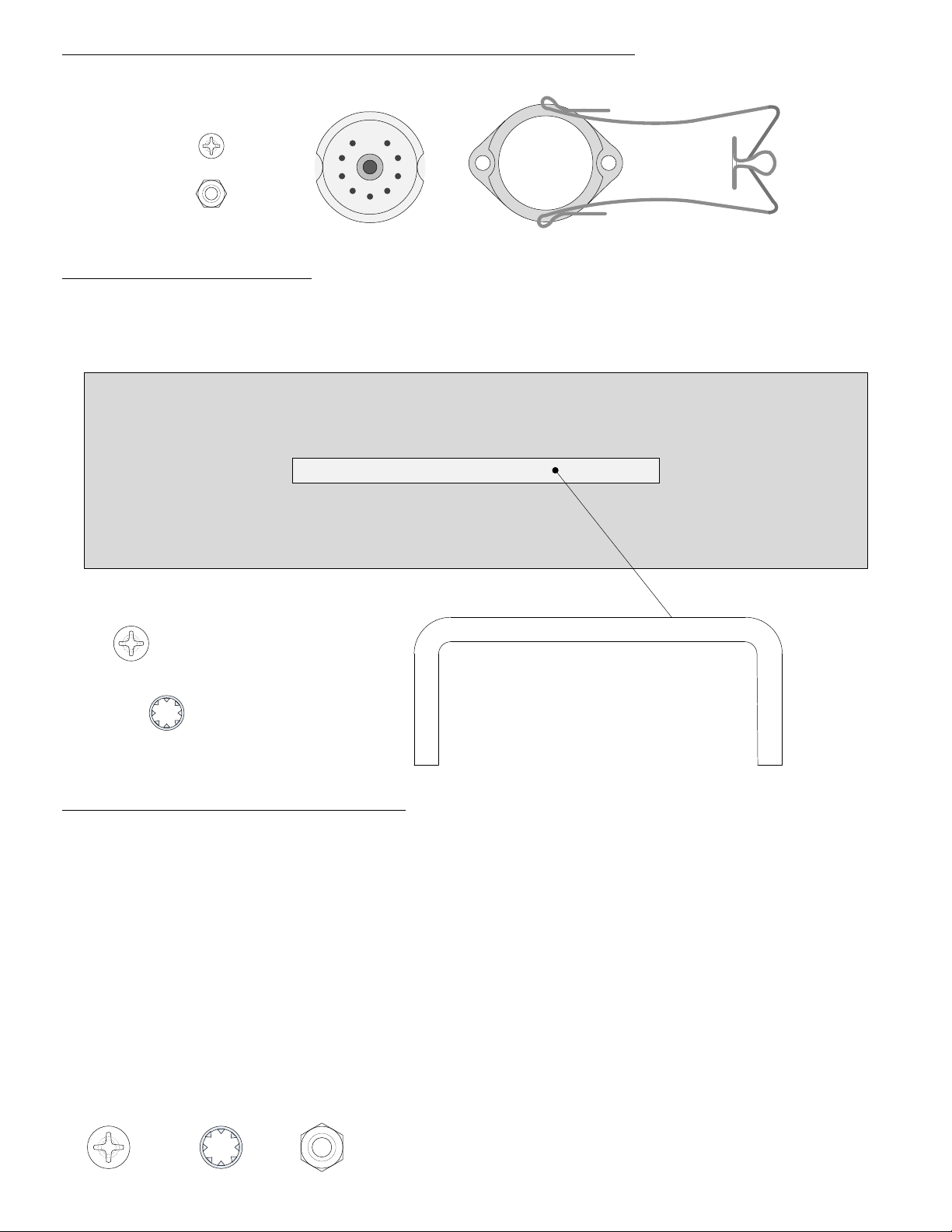
Step 3 – Mount the 9 pin miniature tube socket for the 12AX7 with its tube shield
Drawing 2 shows where to mount the 9 pin miniature socket “V1”. Make sure that pins 1 & 9 face the front
of the chassis. Use #4 hardware and the tube shield to mount this socket.
(2)
(2)
1 9
Tip: Because the tube shield mounting holes are very close to the
socket edge, it may be easiest to fasten the first screw loosely and then
the second screw by holding the hex nut (flat side to socket edge)
against the chassis holes and then inserting the screw from the top of
the chassis. Finish up by fastening both screws tightly.
Top of Chassis
Before you begin!
Use a fine cut miniature round file to carefully file away the paint
coating only from the inside edge of each chassis hole.
(The chassis provides the ground connection for many components so it is
important that the inner edge of these holes are not insulated by the paint coating).
Step 1 – Mount the Labels
Follow the label mounting instructions on page 17 and attach each
label over its corresponding chassis hole.

Step 4 – Mount the 9 pin miniature tube socket with its retainer for the EL84
Drawing 2 shows where to mount the 9 pin miniature socket “V2” and its retainer. Make sure that pins 1 & 9
face the “TR1” side of the chassis. (Use #4 hardware).
(2)
(2)
9
Step 5 – Mount both side handles
Mount both handles to the sides of the chassis box using their supplied #8 hardware. (Doing this step will
help you flip the chassis when mounting the two transformers).
.25
"
Mount both side handles.
(4)
(4)
(2)
Step 6 – Mount the Power Transformer (TR1)
Remove the 369EX power transformer from its packaging. Drawings 2 & 3 show where to mount the power
transformer.
A) Use the first page of the Assembly Drawings, "Primary Wiring Diagrams" to determine which primary
wires you will need to use for your country's mains voltage (100, 110, 120, 200, 220 or 240) and cut off the
unused wires as described in the drawing.
B) Place the transformer on its side and push the wires (one at a time) through their respective grommet holes
as indicated on the drawing.
C) Slowly tilt the transformer upright so that the #10 mounting holes (see drawing 1) line up with the
transformer feet, while continuing to push each bundle of wires through the grommet holes. (Be careful not to
dislodge the rubber grommets).
D) Use #10 mounting hardware to fasten the power transformer in place.
(4) (4) (4)

Step 7 – Mount the Output Transformer (TR2)
Drawing 3 shows where to mount the output transformer P-T31.
A) Hold the transformer up above the chassis and push the wires through their respective grommet holes as
indicated on the drawing.
B) Place the transformer on the chassis so that the mounting holes line up with the transformer feet.
C) Use #6 mounting hardware to fasten the power transformer in place.
(2) (2) (2)
SECTION 2 – Mounting of Front Components
Please refer to Drawing 4.
Step 1 – Mount the Lamp Holder
Drawing 4 shows where to mount the lamp holder. Be sure to mount it so that its solder lugs point towards
the bottom opening of the chassis box. (Once the lamp holder is mounted you may screw in the bulb and then
the jewel).
Step 2 – Mount the Power Switch
Drawing 4 shows where to mount the power switch. Be
sure to mount the power switch with its solder lugs
directed toward the chassis top.
Step 3 – Mount the Bass, Treble, and Volume Pots
Drawing 4 shows where to mount the bass, treble, and volume pots. When they are mounted, turn their shafts all
the way counter-clockwise. (Once you have done this, you can mount the knobs while pointing to “0” and
tightening their set screws).
Step 4 – Mount the Input Jack
Drawing 4 shows where to mount the input jack.
(1)
ccw
010
It is good idea to use a
contact cleaner on each pot
before mounting.
10
Bend back mounting tabs
250KA
Chassis Bottom
(2)
1MA
Chassis Bottom
(1) (3)
Set screw

11
SECTION 3 – Mounting of Rear Components
Please refer to Drawing 4.
Step 1 – Mount the Output Jack
Drawing 4 shows where to mount the output jack.
(1)
Step 2 – Mount the Fuse Holder
Drawing 4 shows where to mount the Fuse holder. You can also insert the 1A fast blow fuse at this time.
SECTION 4 – Mounting Internal Terminal Strips and Passive Components
Please refer to Drawings 5 & 6.
F
U
S
E
F
U
S
E
F
U
S
E
Step 1 – Mount the Terminal Strips
Drawing 5 shows what you should see when you flip the chassis box over so that you are looking inside and
viewing from the rear side with the terminal strips in place. The terminal strips are labeled T1 – T6. (You
will be mounting all 6 terminal strips in this step).
Use #6 hardware and Drawing 5 to mount the 6 terminal strips in the same orientation as in the drawing.
Step 2 – Solder Components to Their Terminal Strip Locations
Please see page 6 “Soldering Tips” if you are new to making solder connections.
Drawing 6 shows each passive circuit component and its respective location on the terminal strip. Be sure to
follow the same orientation of polarity as shown in the drawing for diodes and polarized electrolytic
capacitors.
(7) (7)
T1
T2
T3
T4, T5, T6
Note: Terminal strip terminals are numbered from left
to right with mounting bracket directed towards the
viewer and will be referred to with T6(3) meaning
terminal number 3 on “T6”.
1 2 3 4 5
T6
These instructions will walk you through the mounting of each component so that no components
are missing. Unless noted otherwise, cut the component leads to a reasonable mounting length,
wrap the leads around their connection points and solder. Be sure to leave room on each terminal
for the mounting of future components. You can use Drawings 6 to 9 to anticipate what other
components and wires will be mounted to a particular location.

12
T1
T2
22µF 350V
47µF 350V
22µF 350V
1
3
5
235
2) One 22 µF (350V) cap is soldered with negative end to
T1(1) and positive end to T2(2).
3) The other 22 µF (350V) cap is soldered with negative
end to T1(3) and positive end to T2(3).
Mount the three filter caps:
1) The 47 µF cap is soldered with negative end to T1(5)
and positive end to T2(5).
Connect jumper wires to filter caps:
T1
22µF 350V
47µF 350V
22µF 350V
5 1
3
1) Connect a short length of white wire (about 1.5") from T1(3) to T1(1).
When connecting the wire, you want to strip about ¼” of insulation off of each end to wrap around terminals.
2) Connect a short length of white wire (about 1.5") from T1(3) to T1(5).
Connect T2 components:
1) Connect the 22K 1W resistor from T2(2) to T2(3)
T2
22µF 350V
47µF 350V
22µF 350V
220K
22K
100 2
3
5
7
2) Connect the 100Ω 1W resistor from T2(3) to T2(5)
3) Connect the 220K 1W resistor from T2(5) to T2(7)
3) Connect one diode with the anode to T2(4) and cathode to T2(5).
3) Connect the other diode with the anode to T2(6) and cathode to T2(5).
cathodeanode
cathode side is
marked with a
silver band

Connect T3 components:
1) Connect the 6.8K resistor from T3(2) to the “bass” pot’s cold lug, but do not solder at the cold lug
side, yet.
2) Connect the .047 µF cap from T3(1) to the “bass” pot’s cold lug. Now solder at the “bass” pot’s
cold lug side.
3) Connect the .1 µF cap from T3(1) to the “bass” pot’s wiper lug, but do not solder at the wiper lug
side, yet.
4) Connect a short length of white wire (2.25") from the “bass” pot’s wiper lug to the “treble” pot’s
cold lug. Now solder at the “bass” pot’s wiper lug.
5) Connect a 100K resistor from T3(1) to T4(5).
Connect T4 components:
1) Connect the 250 pF cap from T4(5) to the “treble” pot’s hot lug.
2) Connect a 100K resistor from T4(5) to T4(4).
3) Connect a 22 µF 50V cap with negative end to T4(1) and positive end to T4(3).
4) Connect a 1.5K resistor from T4(1) to T4(3).
5) Connect a short length of white wire (2.25") from T4(5) to V1(1).
6) Connect a short length of white wire (2.25") from T4(3) to V1(3).
Connect T5 components:
1) Connect a short length of white wire (2") from the T5(1) to T5(5). Use the lower terminal holes so
that the wire does not obstruct your mounting of other components.
lower terminal holes
2) Connect a 22 µF 50V cap with negative end to T5(5) and positive
end to V1(8), but do not solder the connection at V1(8), yet.
3) Connect a 1.5K resistor from T5(5) to V1(8). Now solder the connection at V1(8).
4) Connect a 100K resistor from T5(2) to T5(3).
5) Connect a short length of white wire (1.5") from T5(3) to V1(6). Using the lower terminal hole of
T5(3) might make things easier.
6) Connect the .022 µF cap from T5(3) to T6(3).
Connect T6 components:
13
1) Connect the 1K 1W resistor from T6(5) to V2(9).
2) Connect the 5.6K resistor from T6(3) to V2(2).
3) Connect the 220K resistor from T6(3) to T6(1).

5W 200 Ω
1
2 3
4
5
6
7
8
9
V2
5.6K
1K
100µF 100V
4) Connect the 200 Ω resistor from T6(1) to V2(3), but do not solder the connection at V2(3), yet.
14
5) Connect the 100 µF 100V cap with negative end to T6(1) and positive end to both V2(3) and
V2(4), but do not solder the connection at V2(3) or V2(4), yet.
Connect Controls and Input Jack:
1) Connect white wire (about 3.25") from V1(7) to the “volume” pot’s wiper lug.
2) Connect white wire (about 2.75") from V1(2) to the “input” jack’s
signal lug, but do not solder the connection at the “input” jack, yet.
ground
switch
signal
3) Connect white wire (about 2.5") from the “treble” pot’s wiper lug
to the “volume” pot’s hot lug.
4) Connect white wire (about 2") from the “volume” pot’s cold lug to the “input” jack’s ground lug, but
do not solder the connection at the “input” jack, yet.
5) Connect a 1M resistor from the “input” jack’s signal lug to both its switch lug
and ground lug. Add solder to all “input” jack lugs, now.
1M
Connect to the Lamp Holder and Power Switch:
1) Intertwine the two green wires from TR1 and connect their ends to the lower solder lug holes of
the lamp holder. (It does not matter which green wire connects to which lug). Be careful to leave
the upper lug holes open for a future connection to the tube filaments.
2) Connect the "N-Wire(s)" for your country from TR1 to the power switch as shown in Drawing 6.
Allow for some slack before cutting the wire(s) to size. You may find it easier to connect by
temporarily rotating the power switch for access to the solder lugs.
SECTION 6 – Connect Rear Mounted Components
Drawing 7 shows the inside of the chassis as viewed from the front looking at the rear.
1) Intertwine the green and black wires from TR2 and connect their ends to the
output jack with black to the signal lug and green to the ground lug.
ground
signal
2) Connect the "L-Wire(s)" for your country from TR1 to the fuse holder’s outer solder lug. Prop this
lug slightly away from the fuse holder’s plastic body and plan for a little slack before cutting.
Connect to the Output Jack and Fuse Holder:
SECTION 5 – Connect Front Mounted Components
Please refer to Drawing 6.
3) If your country's mains voltage is 200V, 220V or 240V, you will need to intertwine and connect
both "Center-Wires" for your country from TR1 to T1(2). If your country's mains voltage is 100V,
110V or 120V, you should not have any wires to connect for this step.

Insert and Connect the Power Cord:
15
1) Install the grommet with ¼” center into the rear chassis hole.
2) Gently insert the power cord through this grommet hole until at least 18" (1.5 FT) are through.
Tie a knot at the end of the cord so that 1" of black outside insulation extends past the knot. This
knot will serve as a strain relief. Pull the knot as tight as possible by hand. Gently pull the cord
back through the grommet from outside of the chassis until the knot is snug against the inside face
of the grommet.
3) Connect the power cord’s "Neutral (N)" (also known as "Common" or "Return") wire to the other
lug on the power switch (see Drawing 8). You may find it easier to connect by temporarily rotating
the power switch for access to the solder lugs.
4) Connect the power cord’s "Line (L)" (also known as "Hot") wire to the central lug on the fuse
holder.
5) Connect the power cord’s "Earth (E)" (also known as "Ground") wire to T2(1).
SECTION 7 – Finish Connecting the Transformer and Power Supply Wires
Drawing 8 shows the inside chassis as viewed from the rear and looking at the front, again.
Connect the Power Transformer (TR1) Wires:
1) Connect one of the TR1 red wires to T2(6).
2) Connect the other TR1 red wire to T2(4).
3) Connect the TR1 red/yellow wire to T2(1).
Connect the Output Transformer (TR2) Wires:
1) Connect the TR2 red wire to T2(3).
2) Connect the TR2 blue wire to V2(7).
Connect the Tube Power Supply Wires:
1) Connect white wire (about 5.5") from T2(2) to T4(4).
2) Connect white wire (about 3.5") from T4(4) to T6(5).
3) Connect white wire (about 2") from T6(5) to T5(2).
SECTION 8 – Connect the Tube Filament Wiring
Drawing 9 shows the inside chassis view with the filament wiring connected. Use the green wire for these
connections and try to follow the wiring path in the drawing.

Connect the From Lamp Holder to V2:
1) Cut two pieces of green wire (about 8.5” each) and connect one end of each to the lamp holder
solder lugs.
2) Twist these two wires together and fasten, but do not solder, one wire to V2(4) and the other to
V2(5).
3) Cut two more pieces of green wire (about 5.5” each) and connect one wire’s end to V2(4) and the
other wire’s end to V2(5). Now solder all connections at V2(3), V2(4) and V2(5).
4) Twist these two wires together and connect one wire to V1(9) and the other wire to both V1(4)
and V1(5).
Double check your work:
1) At this point, most people will feel anxious to start playing through their amp; however, it’s
important to always double check your work before applying power. Everyone makes mistakes and
it’s easy to forget things. Take some time now to thoroughly double check your work with Drawings
7 & 9. Make sure all solder connections are good and that polarized components are connected the
right way.
1) Use the four self-tap screws to fasten the chassis cover onto the amp.
2) Cut the four rubber bumpers apart from each other, remove their backing and stick them to the
cover to serve as feet. A good place to put them would be near each self-tap screw.
Put the tubes in their sockets:
Attach the Chassis Cover and Rubber Bumpers:
1) Flip the amp over and place the tubes into their respective sockets. The EL84 goes in V2 with
the retainer holding it down.
2) The 12AX7 goes in the V1 socket with the tube shield holding it down.
16
SECTION 9 – Finishing Up
Step 7 – Turn It On and Play
Visit www.modkitsdiy.com if you have any problems when first turning on your amp for
troubleshooting help. If you smell or see smoke, hear something pop, or the chassis becomes too
hot to touch, turn off power and unplug immediately.
The MOD 102 has a single-ended (class A) output stage. There is no need to check the bias, just
plug the amp in, connect the output to a proper 8 ohm load, let the tubes heat up for at least 10
seconds and it’s ready to play.
Remember, that once the amp has been turned on, there will be high voltage (about 260 VDC) on
the filter caps. If the amp has been assembled correctly, it takes about 2 ½ minutes for the voltage
on these caps to drain to less than 1 VDC after the power is turned off.
Always use the one hand rule when working on an amp that has been plugged in (see page 5).

17
Label Mounting Instructions
FRONT
REAR
TOP
½” 11/16" 3/8" 3/8" 3/8" 3/8"
ON/OFF BASS TREBLE VOLUME
The labels are meant to be placed over their respective chassis holes indicated below. There are
four labels for the front panel and two labels for the rear panel.
Cutting the Circle
Each circle on the labels is sectioned into eight
pieces to help you cut out a nice circular shape
for placement over its respective chassis hole.
ON
OFF
ON
OFF
MOD 102
TUBE AMP KIT
BASSBASS
0
1
2
3
456
7
8
9
10
TM
modkitsdiy.com
VOLUMEVOLUME
0
1
2
3
456
7
8
9
10
TREBLETREBLE
0
1
2
3
456
7
8
9
10
ON
OFF
2) Then cut along the circumference, section
by section, removing one sectional piece at a
time.
1) Use a razor or x-acto knife to cut along
each line first.
Ω
3/8" ½” 3/8"
TOP
8 OHM 1 AMP FAST BLO
(FUSE)
This manual suits for next models
2
Table of contents
Other Mod Musical Instrument Amplifier manuals