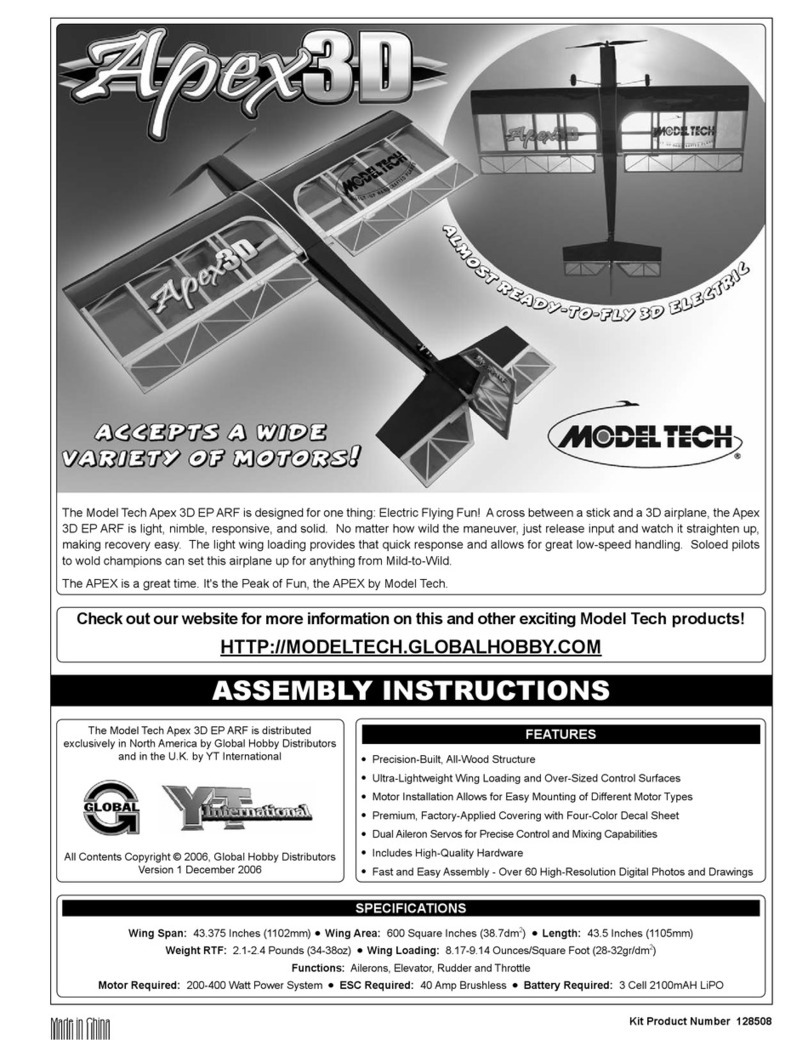
Model Technology Mini Mach Racer User manual

Page 20 Page 1
Fold along dotted line
Global Hobby Distributors
Attn: Global Services
18480 Bandilier Circle
Fountain Valley CA 92728-8610
will not deliver
without proper
postage
_______________________________
_______________________________
_______________________________
(Return Address Here)
Kit Product Number MT3211C
Check out our website for more information on other exciting Model Tech products!
HTTP://MODELTECH.GLOBALHOBBY.COM
Made in China
FEATURES
ASSEMBLY INSTRUCTIONS
Wing Span: 23 Inches (584mm) lWing Area: 250 Square Inches (16.13dm2) lLength: 18 Inches (457mm)
Weight RTF: 16 Ounces (454gr) lWing Loading: 9.5 Ounces/Square Foot (28.12gr/dm2)
Functions: Elevons (Electronic Elevon Mixing) and Throttle lMotor Required: 2208/09 Brushless Outrunner
Electronic Speed Control Required: 18 Amp Brushless lBattery Required: 3 Cell 950mAH LiPO
l Great Flight Characteristics - High Speed Yet Stable Flight Envelope
lAll Wood Construction
l Lightweight, Laser-Cut Parts
l Covered with Iron-On Covering in a Bright, Easy-to-See Colour Scheme
l Easy-Acess Battery Compartment
l High-Quality Hardware
l Detailed Assembly Instructions with Digital Photos
SPECIFICATIONS
Model Tech Co., Ltd.
Hong Kong
© 2008, Model Tech Co., Ltd.
All Rights Reserved
Version 1 May 2008

Page 2 Page 19
These assembly instructions are designed to guide you through the entire assembly process of your new aircraft in the least amount of
time possible. Along the way you'll learn how to properly assemble your new aircraft and also learn tips that will help you in the future.
We have listed some of our recommendations below. Please read through them before beginning assembly.
lPlease read through each step before beginning assembly. You
should nd the layout very complete and straightforward. Our goal
is to guide you through assembly without any of the headaches and
hassles that you might expect.
lThere are check boxes next to each procedure. After you
complete a procedure, check off the box. This will help prevent you
from losing your place.
lCover your work table with brown paper or a soft cloth, both to
protect the table and to protect the parts.
lKeep a couple of small bowls or jars handy to put the small parts
in after you open the accessory bags.
lWe're all excited to get a new aircraft in the air, but take your
time. This will ensure you build a straight, strong and great ying
aircraft.
lIf you come across this symbol +, it means that this is an
important point or an assembly hint.
This R/C aircraft is not a toy! If misused or abused, it can cause serious bodily injury and/or damage to property. Fly only in open
areas and preferably at a dedicated R/C ying site. We suggest having a qualied instructor carefully inspect your aircraft before its rst
ight. Please carefully read and follow all instructions included with this aircraft, your radio control system and any other components
purchased separately.
Model Tech guarantees this kit to be free from defects in both material and workmanship at the date of purchase. This does not cover any component
parts damaged by use, misuse or modication. In no case shall Model Tech's liability exceed the original cost of the purchased kit.
In that Model Tech has no control over the nal assembly or material used for nal assembly, no liability shall be assumed for any damage resulting from
the use by the user of the nal user-assembled product. By the act of using the nal user-assembled product, the user accepts all resulting liability.
TABLE OF CONTENTS
INTRODUCTION
SAFETY WARNING
OUR GUARANTEE
INTRODUCTION.......................................................................... 2
SAFETY WARNING .....................................................................2
OUR GUARANTEE ...................................................................... 2
OUR RECOMMENDATIONS .......................................................3
A NOTE ABOUT COVERING MATERIAL ....................................3
LITHIUM POLYMER BATTERY WARNINGS - PLEASE READ... 4
TOOLS AND SUPPLIES REQUIRED ..........................................5
KIT CONTENTS ........................................................................... 5
TIPS FROM THE PROS...............................................................6
CONTROL SURFACE HINGING..................................................6
ELEVON CONTROL SYSTEM INSTALLATION........................... 7
LANDING SKID AND MOTOR INSTALLATION ...........................9
VERTICAL STABILISERS INSTALLATION ................................12
FINAL ASSEMBLY......................................................................13
C/G AND BALANCING ...............................................................15
AIRCRAFT SETUP INFORMATION...........................................15
CONTROL THROWS ................................................................. 16
PREFLIGHT CHECK AND SAFETY .......................................... 17
REPLACEMENT PARTS LIST ...................................................17
PRODUCT EVALUATION SHEET..............................................19
PRODUCT EVALUATION SHEET
Telling us what you like and don't like determines what model kits we make and how we make them. We would appreciate it if you would take a few
minutes of your time to answer the following questions about this kit and your modeling interests. Simply fold this form on the dotted lines, seal with
tape and mail it to us. Do not use staples and make sure our address faces out.
Global Hobby Distributors will not disclose the information it collects to outside parties. Global Hobby Distributors does not sell,
trade, or rent your personal information to others. Your privacy is important to us.
1) Kit: Model Tech Mini Mach Racer EP ARF # MT3211C
2) Where did you learn about this kit?
qMagazine Ads qFriend
qHobby Shop qOther
qInternet
3) What inuenced you the most to buy this kit?
qMagazine Ads qPrice
qType of Model qBox Art
qRecommendation qOther
qInternet
4) Did you have any trouble understanding the written instructions? If
yes, please explain.
qYes qNo
________________________________________________
________________________________________________
________________________________________________
________________________________________________
5) Did you have any trouble understanding any of the photographs?
If yes, please explain.
qYes qNo
________________________________________________
________________________________________________
________________________________________________
________________________________________________
6) Were any of the kit parts:
qDamaged qWrong Size
qMissing qWrong Shape
If you checked any of the boxes above, did you contact our
Customer Service Department to resolve the problem?
qYes qNo
7) Was any of the assembly difcult for you? If yes, please explain.
qYes qNo
________________________________________________
________________________________________________
________________________________________________
________________________________________________
8) What did you like most about this kit?
qAssembly Manual qParts Fit
qHardware Supplied qPrice
qOther
9) What did you like least about this kit?
qAssembly Manual qParts Fit
qHardware Supplied qPrice
qOther
10) Are you satised with the nished model? If no, please explain.
qYes qNo
_______________________________________________
_______________________________________________
_______________________________________________
_______________________________________________
11) How does this kit compare to similar kits by other manufacturers?
qBetter qAs Good
What is Your Age Group:
q10 & Under q11 - 20 q21 - 30 q31 - 40 q41 - 50 q51 - 60 q61 - 70 q71 +
How Many Years Have You Been in the Hobby?
qLess than 1 q2 - 4 q5 - 7 q8 - 10 q11 - 15 q16 - 20 q20 or More
How Many Models Have You Purchased In the Last Year?
q0 - 1 q2 - 4 q5 - 7 q8 - 10 q10 or More
Please List any Other Modeling Interests or any Additional Information about This Product:
________________________________________________________________________________________________________________________
_________________________________________________________________________________________________________________________
________________________________________________________________________________________________________________________
_________________________________________________________________________________________________________________________
________________________________________________________________________________________________________________________
_________________________________________________________________________________________________________________________
________________________________________________________________________________________________________________________
_________________________________________________________________________________________________________________________
________________________________________________________________________________________________________________________
_________________________________________________________________________________________________________________________
________________________________________________________________________________________________________________________
QC #

Page 18 Page 3
THIS PAGE INTENTIONALLY LEFT BLANK
This section describes our recommendations to help you in deciding which types of accessories to purchase for your new aircraft.
Please read through this entire section very carefully. We have provided you with recommendations that, if
lKMS Quantum 2208/09 Brushless Outrunner
lKMS 18 Amp Brushless ESC
lAPC 6 x 4 Composite Propeller
lImpulse Power 3C 950mAH LiPO Battery
lPro-Peak Quattro DC LiPO Charger
lX'tra 2mm Gold Plugs
The Mini Mach Racer EP ARF is designed to use a brushless outrunner motor and a 3 cell LiPO battery. For good overall ight
performance, we recommend using the KMS Quantum 2208/09 brushless outrunner motor, the KMS 18 amp brushless electronic speed
control, an APC 6 x 4 propeller, and the Impulse Power 3 Cell 950mAH LiPO battery. It's also important that you used high-quality
connectors, such as X'tra 2mm Gold Plugs.
QTY. 1 Airtronics RD6000 FM Radio Control System
QTY. 1 KMS Quantum 2208/09 Brushless Outrunner Motor
QTY. 1 KMS 18 Amp Brushless ESC
QTY. 2 Airtronics 94091Z Micro Servos
QTY. 1 Cirrus RX-8 FM Dual Conversion Receiver
QTY. 1 Cirrus Crystal for FM Dual Conversion Receivers
QTY. 1 Impulse Power 3 Cell 950mAH (25C) LiPO Battery
QTY. 1 APC 6 x 4 Composite Propeller
QTY. 1 Pro-Peak Quattro DC LiPO Charger
QTY. 1 X'tra 2mm Gold Connector Set
QTY. 1 Double-Sided Foam Tape
QTY. 1 Great Planes 1/4" (3mm) Black Striping Tape (Optional)
OUR RECOMMENDATIONS
RECOMMENDED BRUSHLESS POWER SYSTEM
HERE'S A LIST OF WHAT WE RECOMMEND TO FINISH THE MINI MACH RACER EP ARF
You will need to use a 4 or more channel transmitter that features elevon mixing, two 9 gram
micro servos and a micro or mini receiver with matching crystal. At a minimum, the transmitter
should also feature dual rates, servo reversing and end-point adjustments. Do not use
short-range micro receivers.
If your transmitter does not feature elevon mixing, you will need to purchase a separate electronic
elevon mixer that is installed in the aircraft.
The covering material used on your aircraft is real iron-on, heat-shrink covering material. It is possible with heat and humidity changes
that the covering material on your aircraft may wrinkle or sag. This trait is inherent in all types of heat-shrink material. To remove any
wrinkles that might be visible you will need to use a heat-sealing covering iron.
Follow this simple procedure to remove the wrinkles:
qPlug in and turn on the sealing iron to the medium-high temperature setting. Allow the sealing iron to heat up for approximately 5 - 7 minutes.
qAfter the sealing iron has reached temperature, lightly apply the sealing iron to the wrinkled section of the covering material. Move
the sealing iron slowly over the wrinkled section until the covering material tightens and the wrinkles disappear.
+If the color layer smears from any of the seams the temperature of the sealing iron is too hot. Turn the temperature dial down and
wait about 5 minutes for the sealing iron to adjust to the lower temperature. You can remove any excess color streaks using a paper
towel soaked with a small quantity of acetone.
A NOTE ABOUT COVERING MATERIAL
IMPORTANT The elevon servos will plug separately into your receiver or elevon mixer (if your transmitter does not feature elevon
mixing). The use of a Y-Harness for the elevon servos is not necessary.

Page 4 Page 17
Please read and understand the warnings listed in this section. Make sure to read any and all warnings included
in the packaging with your battery, too. If used improperly, lithium polymer batteries can be very dangerous,
so please follow these warnings and suggestions at all times.
l This product may explode or catch re. Serious injury can result from misuse. Serious injury, loss of property, re and death can result
from misuse of this product.
l All instructions, warnings and cautions must be followed at all times. Failure to do so can lead to serious injury or re.
lDo NOT use this product before reading and understanding all directions and warnings.
lDo NOT overcharge. Maximum voltage for each pack must be followed.
lDo NOT over-discharge. NEVER discharge below minimum volts.
lDo NOT discharge at a rate greater than the maximum continuous discharge.
lDo NOT use or charge if the battery is hot.
lONLY use a charger made for Lithium Polymer batteries.
lDo NOT charge at a rate higher than 1C. Example: if the battery’s rating is 340mAH, then the charger’s charge rate must be set at
340mAH or less.
lDo NOT leave in direct sunlight or in a hot car or storage area.
lDo NOT get wet or expose to moisture.
lDo NOT short-circuit the battery.
l ONLY discharge and charge the battery outdoors or in a resafe container.
lDo NOT charge with reverse polarity.
lDo NOT leave the battery connected when not in use.
lDo NOT operate or charge unattended.
lDo NOT solder to the battery directly and do not get the battery hot in any way.
lDo NOT use the product if you do not understand the warnings and proper use of the product.
lAlways let the battery cool and "rest" between uses and charging.
lTo avoid over-discharging, only use a speed control that is made for LiPO batteries.
l We recommend the use of a resafe container when charging or storing.
lDo NOT charge inside your car or inside your house.
lInspect the battery before each use for swelling or other malformation. If the cell has ballooned, it MUST be discarded.
l Set the charger to 1C (charge at 1/2C or less for the rst 5 cycles).
lCheck polarity and then connect battery to charger.
lIn use, do not over-discharge or exceed maximum discharge.
lWhen handling the battery, remember not to poke, bend or damage the cells. The cell's outer casing is soft and can be damaged.
lRemember, the cells must never exceed 160º Fahrenheit (71º Celcius) for any reason.
LITHIUM POLYMER BATTERY WARNINGS - PLEASE READ
WARNINGS AND SAFETY PRECAUTIONS FOR ALL BRANDS OF LITHIUM POLYMER BATTERIES
CHARGING WARNINGS AND PRECAUTIONS FOR ALL BRANDS OF LITHIUM POLYMER BATTERIES
l Completely charge the transmitter and receiver batteries before your rst day of ying.
lCheck every bolt and every glue joint in the aircraft to ensure that everything is tight and well-bonded. This should include all of the
control surface hinges as well.
lDouble-check that you've installed and tightened all of the servo horn retaining screws.
l Double-check that the receiver, ESC and ight battery are properly secured into place. There's nothing worse than the ight battery
coming loose during ight.
lDouble-check the balance of the aircraft. .
lCheck the control surfaces. They should all move in the correct direction and not bind.
l Make sure that you've installed silicone fuel tubing over the clevises to prevent any chance of them opening during ight.
l If your radio transmitter is equipped with dual rate switches, double-check that they are on the low-rate setting for your rst few ights.
lCheck to ensure that all of the control surfaces are moving the proper amount in both low and high rate settings.
lCheck the receiver antenna wire. It should be fully extended and not coiled up inside the radio compartment.
l Do not cut the receiver antenna wire shorter or the range of your radio control system will be greatly reduced.
lProperly balance the propeller. A propeller that is out of balance will cause excessive vibration, which could lead to motor and/or
airframe failure, and it will reduce motor efciency and power.
lDouble-check that the propeller spinner nut is tightened securely.
PREFLIGHT CHECK AND SAFETY
REPLACEMENT PARTS LIST
The following are our general guidelines for your safety and the safety of others. Please read and understand these safety
l Do not test-y your aircraft for the rst time without rst having it safety-checked by an experienced modeler.
l Do not y your aircraft higher than approximately 400 feet within 3 miles of an airport without having an observer with you. The
observer should tell you about any full-size aircraft in your vicinity and you should always give the right-of-way to full-scale aircraft.
l When ying at a ying eld with established rules, you should abide by those rules. You should not deliberately y your aircraft in a
reckless and/or dangerous manner.
l While ying, you should not deliberately y behind the ight line. If your aircraft should inadvertently y behind the ight line, you
should change course immediately.
l You should complete a successful range check of your radio equipment prior to each new day of ying, or prior to the rst ight of a
new or repaired aircraft.
l You should perform your initial turn after take- off away from the ightline and/or spectator area.
l You should not knowingly operate your R/C radio system within 3 miles of a preexisting model club ying eld without a frequency
sharing agreement with that club.
Canopy ............................................................................. 115949
Hatch Cover...................................................................... 115950
Cowling............................................................................. 115951
Vertical Stabilisers ............................................................ 115952
Decal Set .......................................................................... 115953
Assembly Instructions....................................................... 115954
Hardware Set.................................................................... 115955

Page 16 Page 5
qDisconnect the clevis from one elevon control horn, so that the elevon can
be deected fully in both directions.
qRemove the protective backing from the covering material. With the elevon
fully deected in the 'UP' position, place the length of covering material over the
hinge line (on the bottom), making sure that the crease is pushed completely
down into the hinge line.
qPivot the elevon up and down several times to check for free movement, then reconnect the clevis to the control horn and repeat
the previous procedures to seal the hinge gap on the second elevon. The elevons should be able to smoothly pivot completely up and
completely down without interference from the covering material.
q With the elevon fully deected in the 'UP' position, use a heat-sealing
iron to adhere the covering material to both the trailing edge of the wing and
to the leading edge bevel of the elevon.
q Either trim the excess covering material ush with both surfaces or iron it
down onto the wing and the elevon, as shown.
+Only the bottom of the hinge gap needs to be sealed. It is not necessary to seal both the bottom and the top.
It is very important that you understand throttle management. Basically, this means no full throttle dives. Full throttle dives should be
avoided so as not to cause control surface utter and/or airframe failure. When the nose of the aircraft drops, decrease the throttle, just
as in full-scale aircraft.
STEP 2: THROTTLE MANAGEMENT
Ailerons: 3/8" (10mm) Up and Down
Elevator: 3/8" (10mm) Up and Down
Test Flying
We recommend initially setting up the aircraft using the Test Flying control throws. These control throws are suggested for initial test ying
because they will allow the aircraft to y smoother and make it easier to control. You can increase the control throws to suit your ying
style, but only AFTER you've become very familiar with the ight characteristics of the aircraft using the Test Flying control throws.
CONTROL THROWS
q After you're nished adjusting the control throws, you need to cut two 1/4"
(6mm) lengths of silicone fuel tubing and slide one piece over each clevis. The
tubing will prevent any chance of the clevises opening during ight.
The aircraft requires approximately 1mm of Reex (both control surfaces up)
for neutral. To set the Reex, centre both elevons with the wing tips, then adjust
the pushrods so that both elevons are 1mm up from centre. This is the neutral
point and should be the point where the control throws are measured.
q220 Grit Sandpaper
qSanding Block
qMasking Tape
qPaper Towels
qRubbing Alcohol
qEpoxy Mixing Sticks
qEpoxy Mixing Cups
qSoldering Iron
qSolder
qHeat-Shrink Tubing (Assorted Sizes)
qHeat Gun (for Heat-Shrink Tubing)
qHeat Sealing Iron (for Covering Material)
qWhite Covering Material 1/2" x 24" (1.3cm x 61cm)
q5 Minute Epoxy
qThin and Thick C/A
qC/A Debonder
qFormula 560 Canopy Glue
q# 1 and # 2 Phillips Head Screwdrivers
qWire Cutters
qNeedle Nose Pliers
qModeling Knife
qScissors
qElectric or Hand Drill
qAssorted Drill Bits
qStraight Edge Ruler
qPencil
qBuilder's Triangle
Before you begin assembly, group the parts as we list them below. This will ensure that you have all of the parts before you begin assembly
and it will also help you become familiar with each part.
q(1) Wing with Hatch Cover
q(1) Right Elevon
q(1) Left Elevon
q(2) Vertical Stabilisers
q(2) 5-3/4" (146mm) Threaded Wires with Z-Bends
q(2) Nylon Control Horns with Backplates
q(2) Nylon Clevises
q(6) M2 x 16mm Machine Screws
q(6) C/A-Style Hinges
q(1) Cowling
q(1) Canopy
q(1) Landing Skid
q(2) Plywood Spacer Plates
q(1) Hook and Loop Material
q(4) M3 x 12mm Machine Screws
q(4) M3 x 18mm Machine Screws
q(4) M3 Flat Washers
q(4) M2 x 10mm Washer-Head Wood Screws
q(1) Decal Sheet (Not Pictured)
KIT CONTENTS
AIRFRAME ASSEMBLIES
CONTROL SYSTEM ASSEMBLIES
MISCELLANEOUS PARTS
TOOLS AND SUPPLIES REQUIRED

Page 6 Page 15
lDuring the covering process, sometimes color may smear slightly from the seams. If you see any smeared colors on the covering
material, they can be quickly removed by simply wiping them off with a paper towel and a small amount of acetone.
l Make sure to test-t the parts together before applying glue. This will ensure that the parts t properly before gluing them together.
lWhen gluing anything that has a smooth surface, it's important to lightly roughen the gluing surfaces with 220 grit sandpaper. This
will allow the glue to stick better. Also, never glue directly to the covering material. Always remove the covering material from the gluing
surfaces prior to gluing the parts together.
lWhen cutting away the covering material from the gluing surfaces, be careful to cut only through the covering material. Try not to cut
down into the balsa structure because that can compromise the integrity of the airframe.
lWe do not suggest storing your aircraft in an extremely hot environment (like the back of your car in direct sunlight) for any length of
time. The extreme heat could cause the covering material to wrinkle or sag and possibly damage the fragile components of the radio
control system and/or LiPO battery.
lEpoxy can be cleaned up before it dries using rubbing alcohol, and C/A can be cleaned up before it dries using C/A Debonder.
lTo prevent current loss, make sure to use high-quality connectors between the battery and the ESC, and between the ESC and
the motor.
lInsulate solder joints with heat-shrink tubing to prevent short circuits and corrosion.
TIPS FROM THE PROS
qThin C/A
qC/A Debonder
qModeling Knife
q(1) Wing with Hatch Cover
q(1) Right Elevon
q(1) Left Elevon
q(6) C/A-Style Hinges
qT-Pins
qPaper Towels
CONTROL SURFACE HINGING
YOU'LL NEED THE FOLLOWING PARTS FROM THE KIT:
YOU'LL NEED THE FOLLOWING TOOLS AND SUPPLIES:
STEP 1: HINGING THE ELEVONS
IMPORTANT The hinges are NOT glued into place from the factory, they are simply slid into place dry for shipping purposes. You
must glue them into place.
C/A-style hinges are used to hinge the control surfaces. These hinges are designed to be glued into place using thin C/A. Do not
glue these hinges into place using any other type of glue, such as thick C/A or epoxy. Use of any adhesive other than thin C/A could
result in failure of the hinges during ight.
For utter-free control surfaces and crisp control response, it is imperative that the hinges be glued in properly. This is achieved by
having a tight hinge gap [no more than 1/32" (.7mm) wide] and using plenty of thin C/A glue. Poor hinge installation can lead to control
surface utter which can result in a catastrophic failure of the airframe.
PRO TIP The T-Pins will keep the hinges centred and square to the hinge
line while you are hinging the elevon.
qWorking with one elevon for now, push two T-Pins through the centre of
each of the three hinges.
qRemove the two elevons and the six C/A-style hinges from the wing.
C/G AND BALANCING
IMPORTANT It is critical that your aircraft be balanced correctly. Incorrectly balancing your aircraft can cause your aircraft to lose
control and crash!
+ Once you have own and become familiar with the ight characteristics of the aircraft, the C/G can be moved fore or aft to change
the ight performance. Moving the C/G back will cause the aircraft to be more responsive and aerobatic, but less stable. Moving the C/G
forward will cause the aircraft to be more stable, but less responsive. See warning above.
qApply two short pieces of masking tape onto the TOP of the aircraft,
sides of the of the radio compartment.
q Turn the aircraft over (upside down) and place your ngers on the masking tape, then carefully lift the aircraft. If the nose of the
aircraft falls, the aircraft is nose heavy. To correct this, move the ight battery back far enough to bring the aircraft into balance. If the
tail of the aircraft falls, the aircraft is tail heavy. To correct this, move the ight battery and/or receiver and ESC forward far enough to
bring the aircraft into balance.
IMPORTANT When balanced correctly, the aircraft should sit level or slightly nose down when you lift it up with your ngers at
the C/G location.
l
MEASURED AT THE SIDES OF THE RADIO COMPARTMENT.
This is the recommended C/G location for test-ying. After you
become familiar with the ying characteristics of the aircraft, you can move
the C/G forward or backward to suit your ying style. We suggest moving the
qStraight Edge Ruler qMasking Tape
YOU'LL NEED THE FOLLOWING TOOLS AND SUPPLIES:
AIRCRAFT SETUP INFORMATION
Before adjusting the control throws and ying your new aircraft, there are some points about the aircraft's setup that you should be aware
of. We strongly suggest following these suggestions to get the most enjoyment out of your aircraft.
Because of the high speed that the aircraft ies at, we suggest that the elevon hinge gaps be sealed. Failure to do this can lead to control
surface utter, which can cause your aircraft to crash. Sealing the hinge gaps will also provide crisper control response and allow the
aircraft to track straighter and y truer, making trimming much easier.
The hinge gaps can be sealed using heat-shrink covering material or clear vinyl tape. To seal the hinge gaps using heat-shrink covering
material, follow these procedures:
STEP 1: SEALING THE HINGE GAPS
qCut a piece of covering material 3/8" (10mm) wide and 8" (203mm) long.
qFold the length of covering material in half lengthwise so that there is a
sharp crease down the middle of the covering material.
4-1/4" (108mm)

Page 14 Page 7
STEP 3: INSTALLING THE FLIGHT BATTERY
IMPORTANT The nal location that the ight battery is mounted in will
depend on where the aircraft balances, as described in the next section.
qCarefully solder matching plugs onto the two battery wires on your battery
and the two battery wires on your ESC.
q Mount your ight battery to the front of the radio compartment oor, using
the strip of hook and loop material provided.
STEP 4: INSTALLING THE CANOPY AND THE HATCH COVER
qCarefully cut out the canopy along the moulded scribe line, then sand the
edges of the canopy smooth.
qSet the canopy onto the hatch cover and align it. When aligned properly,
the sides of the canopy should be centred between the sides of the hatch cover
and the front of the canopy should be approximately 3/8" (10mm) behind the
front of the hatch cover.
q When satised with the alignment, glue the canopy to the hatch cover, using a thin layer of Formula 560 Canopy Glue.
PRO TIP To enhance the appearance, apply a strip of 1/4" (6mm) wide black striping tape around the base of the canopy.
q Install the hatch cover onto the wing, making sure that the magnets hold the back of the hatch cover rmly in place.
STEP 5: INSTALLING THE PROPELLER
qInstall your propeller onto your motor, making sure that it's securely in place
and doesn't touch the front of the cowling.
IMPORTANT To make sure that the motor can't accidentally be turned on
while you're installing your propeller, unplug the ight battery from the ESC
before installing the propeller.
qCut away the covering material from over the air exit hole in the back of the
radio compartment.
qPush the elevon and hinges into the corresponding three hinge slots in the
trailing edge of the wing.
qSlide one hinge into each of the three hinge slots in the elevon, making sure
that you push each hinge in up to the T-Pins.
IMPORTANT Don't glue the hinges into the elevon yet.
qAllow the C/A to dry for about 15 minutes, then pivot the elevon up and down several times to free up the hinges.
qRemove the T-Pins and push the elevon up against the trailing edge. There
should be no more than a 1/32" (.7mm) wide hinge gap and the outer end of
the elevon should not touch the wing when the elevon is deected.
qWhile holding the elevon tight against the trailing edge, pivot the elevon
down 45º and apply 5-6 drops of thin C/A to the exposed area of each hinge,
then turn the wing over and repeat for the other side of the hinges.
IMPORTANT Check the integrity of the hinges after the C/A fully cures by gently pulling on the elevon. If one or more hinges feels
loose, apply more C/A to the hinge(s) and allow it to completely cure. The last thing you want is for a hinge to come loose
during ight.
qRepeat the previous procedures to hinge the second elevon to the other
side of the wing.
qThin C/A
q# 1 Philips Head Screwdriver
qNeedle Nose Pliers
qModeling Knife
qElectric or Hand Drill
q(2) 5-3/4" (146mm) Threaded Wires with Z-Bends
q(2) Nylon Control Horns with Backplates
q(2) Nylon Clevises
q(6) M2 x 16mm Machine Screws
q1/16" (1.6mm) and 5/64" (2mm) Drill Bits
qStraight Edge Ruler
qPencil
qMasking Tape
ELEVON CONTROL SYSTEM INSTALLATION
YOU'LL NEED THE FOLLOWING PARTS FROM THE KIT:
YOU'LL NEED THE FOLLOWING TOOLS AND SUPPLIES:

Page 8 Page 13
STEP 1: INSTALLING THE ELEVON SERVOS
qCut away the covering material from over the two elevon servo mounting
holes in the bottom of the wing. One servo mounting hole is located on each
side of the wing, 1/2" (13mm) out from the sides of the radio compartment and
6" (152mm) in front of the elevon hinge lines.
qWorking with one elevon servo for now, run the servo lead through the
precut slot in the inboard side of the servo mounting hole and into the radio
compartment.
STEP 2: INSTALLING THE ELEVON CONTROL LINKAGES
qPosition and mark the mounting hole locations for the control horn on the
bottom of one elevon. When aligned properly, the centreline of the control horn
should be positioned 1-1/4" (32mm) out from the inboard edge of the elevon
(measured at the hinge line) and the clevis attachment holes should be lined
up over the hinge line. The base of the control horn should be parallel to the
hinge line, too.
qDrill 5/64" (2mm) diameter pilot holes through the elevon for the control horn
mounting screws, then apply a couple of drops of thin C/A into the pilot holes.
Allow the C/A to fully cure.
+The C/A will harden the surrounding wood, making the mounting area
stronger.
qInstall the control horn and backplate, using three M2 x 16mm machine screws, then use wire cutters to cut the top of the screws
ush with the control horn backplate.
IMPORTANT Depending on the dimensions of your elevon servo, you may need to cut the servo mounting hole slighly larger to
t before installing the servo in the next procedure.
qInstall your elevon servo into the servo mounting hole, using the mounting
screws provided with your servo, then repeat the previous procedures to install
the second elevon servo into the other half of the wing.
IMPORTANT The servo output shaft should be toward the front of
the wing.
+Make sure to drill pilot holes through the wing for the servo mounting
screws.
qFormula 560 Canopy Glue
q# 2 Philips Head Screwdriver
qWire Cutters
qModeling Knife
qScissors
qStraight Edge Ruler
q220 Grit Sandpaper with Sanding Block
qMasking Tape
q(1) Canopy q(1) Hook and Loop Material
qPaper Towels
qSoldering Iron
qSolder
qHeat Shrink
qHeat Gun
qHeat Sealing Iron
qWhite Covering Material 1/2" x 24" (1.3cm x 61cm)
FINAL ASSEMBLY
YOU'LL NEED THE FOLLOWING PARTS FROM THE KIT:
YOU'LL NEED THE FOLLOWING TOOLS AND SUPPLIES:
STEP 1: INSTALLING THE ELECTRONIC SPEED CONTROL
PRO TIP If the the motor spins the wrong direction when powered up, swap two of the three motor wires and check again. The
motor should spin counter-clockwise when viewed from the front. Do not swap the positive and negative battery wires to change
the direction that the motor spins or you will damage both your ESC and your LiPO battery.
qCarefully solder three matching plugs onto your motor and onto your ESC. Be sure to apply heat-shrink tubing over the solder joints
to insulate them from shorting out.
qMount your ESC to the front left side of the radio compartment, using a
piece of double-sided foam tape (not included).
STEP 2: INSTALLING THE RECEIVER
qCut away the covering material from over the receiver antenna wire exit slot
in the top right half of the wing. The receiver antenna wire exit slot is located
1-1/8" (29mm) in front of the elevon hinge line and 1/2" (13mm) in from the
side of the vertical stabiliser.
qPlug the servo and ESC leads into their proper slots in your receiver, then
mount your receiver to the back of the radio compartment oor, using a piece
of double-sided foam tape (not included).
IMPORTANT Mount your receiver as far away from the ESC as possible
to help prevent radio interference.
qUncoil the receiver antenna wire and feed it through the tube in the forward right side of the radio compartment. The tube is located
4-3/4" (121mm) behind on the rewall on the right side of the radio compartment.
IMPORTANT Do not cut the receiver antenna wire shorter. Allow the excess to hang past the back of the aircraft.

Page 12 Page 9
q5 Minute Epoxy
qModeling Knife
qStraight Edge Ruler
qPencil
qBuilder's Triangle
q(2) Vertical Stabilisers
qPaper Towels
qRubbing Alcohol
qEpoxy Mixing Sticks
qEpoxy Mixing Cups
VERTICAL STABILISERS INSTALLATION
YOU'LL NEED THE FOLLOWING PARTS FROM THE KIT:
YOU'LL NEED THE FOLLOWING TOOLS AND SUPPLIES:
STEP 1: ALIGNING THE VERTICAL STABILISERS
qCut away the covering material from over the two vertical stabiliser mounting
slots in the top of the wing. Each mounting slot is 3/16" (5mm) wide and 3-3/8"
(86mm) long. The back edge of each mounting slot is located 1-1/8" (29mm)
in front of the elevon hinge line and the centre of each mounting slot is 2-1/2"
(64mm) out from each side of the radio compartment.
qPush one vertical stabiliser down into one mounting slot, then draw a line on
each side of the vertical stabiliser where it meets the top of the wing. Draw an
outline onto the top of the wing around the base of the vertical stabiliser, too.
When cutting through the covering to remove it in the next step, cut with only enough pressure to cut through only the
covering itself. Cutting down into the balsa structure could weaken the vertical stabiliser and cause it to fail during ight.
qRemove the vertical stabiliser and cut away the covering material from both
sides of the vertical stabiliser and from the base of the vertical stabiliser, too.
qCarefully cut away the covering material from within the outline you drew
on top of the wing.
qGlue the vertical stabiliser into place, using 5 minute epoxy. Wipe away any
excess epoxy and hold the vertical stabiliser in place until the epoxy has
set up.
IMPORTANT Use a builder's triangle to make sure that the vertical
stabiliser is perpendicular to the wing.
qRepeat the previous procedures to align and install the second vertical
stabiliser on the other half of the wing.
STEP 2: INSTALLING THE VERTICAL STABILISERS
qEnlarge the hole in one servo arm that is 3/8" (10mm) out from the centre
of the servo horn, using a 1/16" (1.6mm) diameter drill bit.
qInstall the Z-Bend in one pushrod wire into the hole that you enlarged in the
servo arm.
+The pushrod wire should be orientated on top of the servo arm.
qCentre the elevon servo, then install the servo horn onto the servo, making
sure that the servo horn is centred and pointing out toward the wing tip.
qInstall the servo horn retaining screw to secure the servo horn to the servo.
qWith both the servo horn and the elevon centred, thread one clevis onto the
pushrod wire and snap the clevis into the outermost hole in the control horn.
qRemove the masking tape and double-check that both the servo horn and
the elevon are still centred. If necessary, thread the clevis in or out to centre
the elevon, then move the elevon up and down several times to ensure proper
movement.
qUse a couple of pieces of masking tape, taped between the elevon and the wing, to hold the elevon centred.
qRepeat the previous procedures to install the second elevon control linkage
onto the other half of the wing.
qThin and Thick C/A
q# 2 Philips Head Screwdriver
qModeling Knife
qScissors
qElectric or Hand Drill
q(1) Cowling
q(1) Landing Skid
q(2) Plywood Spacer Plates
q(4) M3 x 12mm Machine Screws
q(4) M3 x 18mm Machine Screws
q(4) M3 Flat Washers
q(4) M2 x 10mm Washer-Head Wood Screws
q1/16" (1.6mm) Drill Bit
qStraight Edge Ruler
qPencil
q220 Grit Sandpaper with Sanding Block
qMasking Tape
LANDING SKID AND MOTOR INSTALLATION
YOU'LL NEED THE FOLLOWING PARTS FROM THE KIT:
YOU'LL NEED THE FOLLOWING TOOLS AND SUPPLIES:

Page 10 Page 11
STEP 2A: INSTALLING THE MOTOR - WITH BOLT-ON THREADED PROPELLER ADAPTER
STEP 1: INSTALLING THE LANDING SKID
qCut away the covering material from over the landing skid mounting slots in
the bottom of the wing, then test-t and glue the landing skid rmly into place,
using a generous amount of thick C/A.
IMPORTANT Make sure to cut away the covering material from over
the gluing surfaces to ensure a strong bond.
IMPORTANT Two different types of motor are showed installed. The rst type shown in step 2A is an outrunner motor that uses a
backplate mount and a bolt-on threaded propeller adapter. This type of motor requires using the two plywood spacer plates and four
18mm long machine screws to install. The second type shown in step 2B is an outrunner motor that uses a backplate mount and a
slide-on propeller adapter. This type of motor does not require any spacer plates and uses four12mm long machine screws to install.
Please follow the step that matches the motor type that you're using.
qInstall the propeller adapter and the backplate mount (both included with
your motor) onto your brushless outrunner motor, following the procedures in
your motor's user's guide.
qInstall your motor, using two plywood spacer plates, four M3 x 18mm
machine screws and four M3 at washers, making sure to tighten the machine
screws rmly.
IMPORTANT The two plywood spacer plates are provided to push
your motor out far enough so that the front of the propeller adapter is
approximately 1/16" (1.6mm) in front of the fuselage sides.
IMPORTANT The preinstalled blind nuts in the rewall are spaced to t a majority of 4-hole radial backplate mounts of motors
within the specications of the aircraft. If your motor's backplate mount uses a different mounting hole pattern, you will need to drill new
mounting holes and reinstall the blind nuts to match.
STEP 2B: INSTALLING THE MOTOR - WITH SLIDE-ON PROPELLER ADAPTER
IMPORTANT The preinstalled blind nuts in the rewall are spaced to t a majority of 4-hole radial backplate mounts of motors
within the specications of the aircraft. If your motor's backplate mount uses a different mounting hole pattern, you will need to drill
new mounting holes and reinstall the blind nuts to match.
qInstall the backplate mount (included with your motor) onto your brushless
outrunner motor, following the procedures in your motor's user's guide.
STEP 3: INSTALLING THE COWLING
q When satised with the t and alignment, hold the cowling securely in place,
using a couple of pieces of masking tape.
qDrill two 1/16" (1.6mm) diameter pilot holes through each side of the
cowling for the wood screws. Position one pilot hole centred between the top
of the cowling and the top of the wing, and one pilot hole centred between the
bottom of the cowling and the bottom of the wing. All four pilot holes should be
1/8" (3mm) in front of the back edge of the cowling.
qSlide the cowling onto the front of the aircraft and align it. When aligned
properly, the hole in the middle of the cowling should be centred around the
motor shaft and the back of the cowling should t ush against the surface of
the aircraft. The cutouts in the side of the cowling should t over the contour
of the wing leading edges, too.
IMPORTANT You may need to cut a notch in the bottom of the cowling
to t around the front of the landing skid.
qCut out the back of the cowling along its base, making sure to cut the back
edge straight.
qUsing the moulded scribe lines as a guide, cut out the sides of the cowling to
clear the wing leading edges, then cut out the holes in the front and the bottom
of the cowling for the propeller adapter and the three cooling intake holes.
IMPORTANT Depending on the motor that you're using, you may need
to cut out more of the front of the cowling than shown.
qRemove the cowling and apply a couple of drops of thin C/A into the four
pilot holes and allow the C/A to fully cure.
qInstall the cowling, using four M2 x 10mm washer-head wood screws.
q Install your motor, using four M3 x 12mm machine screws and four M3 at
washers, making sure to tighten the machine screws rmly.
IMPORTANT It's not necessary to use the two plywood spacer plates
with this type of motor.
Table of contents
Other Model Technology Toy manuals