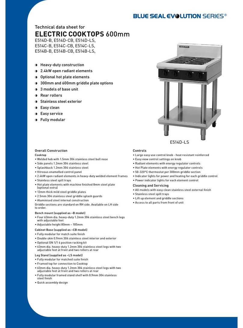
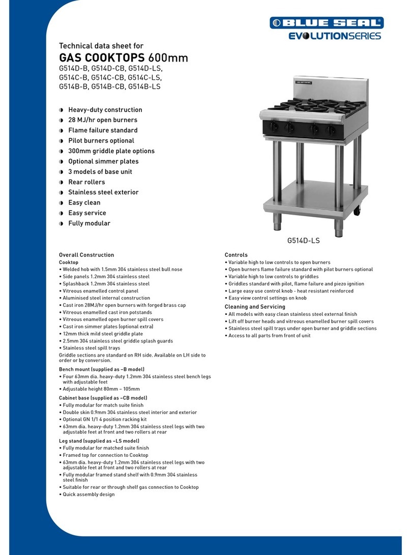
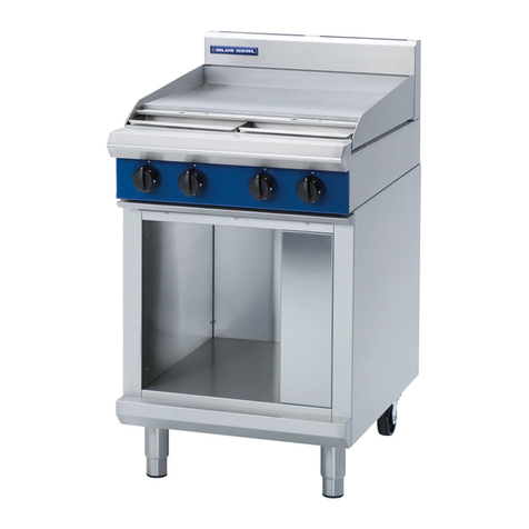
Moffat BLUE SEAL EVOLUTION Series User manual

Blue Seal Evolution Series Electric Cooktops © Copyright Moffat Ltd, April 2016
Amendment 4
Service Manual
Electric Cooktops
E512 / E514 / E516

Blue Seal Evolution Series Electric Cooktops © Copyright Moffat Ltd, April 2016
Amendment 4
ALL INSTALLATION AND SERVICE REPAIR WORK MUST BE CARRIED OUT BY QUALIFIED PERSONS
ONLY.
WARNING:
MAKING ALTERATIONS MAY VOID WARRANTIES AND APPROVALS.
IMPORTANT:

Contents
Blue Seal Evolution Series Electric Cooktops © Copyright Moffat Ltd, April 2016
Amendment 4
This manual is designed to take a more in depth look at the Blue Seal E51 Electric Cooktops for the purpose of making the units more
understandable to service people.
There are settings explained in this manual that should never require to be adjusted, but for completeness and those special cases
where these settings are required to change, this manual gives a full explanation as to how, and what effects will result.
Section Page No.
1. Specifications ........................................................................................................................... 3
2. Installation ............................................................................................................................. 10
3. Operation ................................................................................................................................ 13
3.1 Description of Controls
4. Maintenance ........................................................................................................................... 14
Maintenance Schedule
5. Fault Finding Guide ................................................................................................................ 15
5.1 Fault Finding Chart
5.2 Fault Diagnosis
6. Service Procedures ................................................................................................................. 17
6.1 Access
6.2 Replacement
6.3 Adjustment / Calibration
7. Accessories ............................................................................................................................. 22
8. Exploded Parts Diagrams ....................................................................................................... 23
8.1 E51 Electric Cooktops
8.2 E51 Base Options
9. Wiring Diagrams..................................................................................................................... 28
10. Service Contacts ..................................................................................................................... 33
Contents

Contents
Blue Seal Evolution Series Electric Cooktops © Copyright Moffat Ltd, April 2016
Amendment 4

3
1
Specifications
Blue Seal Evolution Series Electric Cooktops © Copyright Moffat Ltd, April 2016
Amendment 4
Dimensions for Bench Models
E514-B
E512-B
E516-B
= Rating Plate Location for this option.R
R

4
1
Specifications
Blue Seal Evolution Series Electric Cooktops © Copyright Moffat Ltd, April 2016
Amendment 4
Dimensions for Cabinet Base Models
E514-CB
E516-CB
= Rating Plate Location for this
option.
R
R

5
1
Specifications
Blue Seal Evolution Series Electric Cooktops © Copyright Moffat Ltd, April 2016
Amendment 4
Dimensions for Leg Stand Models
E514-LS
E516-LS
= Rating Plate Location for this
option.
R
R

6
1
Specifications
Blue Seal Evolution Series Electric Cooktops © Copyright Moffat Ltd, April 2016
Amendment 4
Dimensions for Refrigerated Base Models
E516-RB
E512D
Cooktop Options
E512-C
For the Refrigeration Cabinet Operation refer to the Refrigeration Cabinet Installation and Operation Manual supplied with the
appliance.
= Rating Plate Location for this
option.
R
R

7
1
Specifications
Blue Seal Evolution Series Electric Cooktops © Copyright Moffat Ltd, April 2016
Amendment 4
NOTE:
E512 is only available as Bench Mount (B) Model.
E514 is available as Bench Mount (B), Cabinet Base (CB) or Leg Stand (LS) model options.
E516 is available as Bench Mount (B), Cabinet Base (CB), Leg Stand (LS), or Refrigerated Base (RB) model
options.
For the Refrigeration Cabinet Dimensions, refer to the Refrigeration Cabinet Installation and Operation Manual supplied with
the appliance.
E516B E516A
Cooktop Options
E516D
E514-D E514-C
E516C
E514-B

8
1
Specifications
Blue Seal Evolution Series Electric Cooktops © Copyright Moffat Ltd, April 2016
Amendment 4
Model Numbers Covered in this Specification
E512D-B Bench Model 2 Open Radiant Elements.
E512C-B Bench Model 300 mm Griddle.
E514D-B Bench Model 4 Open Radiant Elements.
E514D-CB with Cabinet Base 4 Open Radiant Elements.
E514D-LS with Leg Stand 4 Open Radiant Elements.
E514C-B Bench Model 2 Open Radiant Elements / 300 mm Griddle.
E514C-CB with Cabinet Base 2 Open Radiant Elements / 300 mm Griddle.
E514C-LS with Leg Stand 2 Open Radiant Elements / 300 mm Griddle.
E514B-B Bench Model 600 mm Griddle.
E514B-CB with Cabinet Base 600 mm Griddle.
E514B-LS with Leg Stand 600 mm Griddle.
E516D-B Bench Model 6 Open Radiant Elements.
E516D-CB with Cabinet Base 6 Open Radiant Elements.
E516D-LS with Leg Stand 6 Open Radiant Elements.
E516D-RB with Refrigeration Base 6 Open Radiant Elements.
E516C-B Bench Model 4 Open Radiant Elements / 300 mm Griddle.
E516C-CB with Cabinet Base 4 Open Radiant Elements / 300 mm Griddle.
E516C-LS with Leg Stand 4 Open Radiant Elements / 300 mm Griddle.
E516C-RB with Refrigeration Base 4 Open Radiant Elements / 300 mm Griddle.
E516B-B Bench Model 2 Open Radiant Elements / 600 mm Griddle.
E516B-CB with Cabinet Base 2 Open Radiant Elements / 600 mm Griddle.
E516B-LS with Leg Stand 2 Open Radiant Elements / 600 mm Griddle.
E516B-RB with Refrigeration Base 2 Open Radiant Elements / 600 mm Griddle.
E516A-B Bench Model 900 mm Griddle.
E516A-CB with Cabinet Base 900 mm Griddle.
E516A-LS with Leg Stand 900 mm Griddle.
E516A-RB with Refrigeration Base 900 mm Griddle.
Base Stand Options:
-B Bench Model (All Models).
-CB with Cabinet Base (E514 / E516 Models only).
-LS with Leg Stand (E514 / E516 Models only).
-RB with Refrigeration Base (E516 Models Only).
General
A commercial heavy duty, high efficiency Cooktop for modular kitchens, constructed in easy clean stainless steel external
finish. Hinge-up elements and griddle sections and all services are accessed from the front of the units. It has a high option
hob/griddle arrangement with 300mm, 600mm or 900mm griddle or open radiant element options.
It is available on industrial adjustable feet. With 3 models of base unit available from the E512 to E516 models. (Model E514
is not available with Refrigeration Base option and Model E512 is only available in Bench Model).
9
1
Specifications
Blue Seal Evolution Series Electric Cooktops © Copyright Moffat Ltd, April 2016
Amendment 4
Electrical Supply Requirements
Electrical Connection
Electrical supply connection point is located at the rear of the appliance, approximately 130mm from the right hand side and 31mm
from the rear of the appliance. 85mm from bench height on bench models and 740mm from the floor on leg stand and cabinet base
models. (Refer to the ‘Dimensions’ section).
When connecting a this electric appliance to the mains supply, ensure that the following is carried out:-
An isolating switch is fitted within 2 m of the appliance, but not on the appliance and in such a position that the user does not
have to reach across the cooking surface.
Supply cord shall be oil-resistant, sheathed flexible cable and not lighter than ordinary polychloroprene or other equivalent
synthetic elastomer sheathed cord (as per AS/NZS 3191 part 2.10.11. or IEC 60245-IEC-57) e.g. HO5 RN-F Type.
The branch supply line shall be individually overload protected to the correct current rating and the supply chord shall be
protected against any mechanical or thermal damage.
A grommet is fitted around the wiring entry hole into the appliance.
All wiring connections must be tight.
Refer to the appropriate wiring standards for the size of cable that is to be supplied to an appliance for the current drawn on that line.
For the Refrigeration Cabinet Specifications, refer to the Refrigeration Cabinet Installation and Operation Manual supplied
with the appliance.
Model Power Supply Total Power
Input
Amps
Voltage Type Frequency L1 L2 L3
E512D 230-240 Vac 1 P+N+E 50 / 60 Hz 4.8 kW 20.0 --- ---
E512C 230-240 Vac 1 P+N+E 50 / 60 Hz 3.4 kW 14.2 --- ---
E514D 400-415 Vac 2 P+N+E 50 / 60 Hz 9.6 kW 20.0 20.0 ---
E514C 400-415 Vac 2 P+N+E 50 / 60 Hz 8.2 kW 14.2 20.0 ---
E514B 400-415 Vac 2 P+N+E 50 / 60 Hz 6.8 kW 14.2 14.2 ---
E516D 400-415 Vac 3 P+N+E 50 / 60 Hz 14.4 kW 20.0 20.0 20.0
E516C 400-415 Vac 3 P+N+E 50 / 60 Hz 13.2 kW 14.2 20.0 20.0
E516B 400-415 Vac 3 P+N+E 50 / 60 Hz 11.6 kW 14.2 14.2 20.0
E516A 400-415 Vac 3 P+N+E 50 / 60 Hz 10.2 kW 14.2 14.2 14.2
THIS APPLIANCE MUST BE EARTHED. IFSUPPLY CORD IS DAMAGED, IT MUST BE REPLACED BY ASUITABLY QUALIFIED PERSON IN
ORDER TO AVOID AHAZARD.
Warning

2
Installation
10
Blue Seal Evolution Series Electric Cooktops © Copyright Moffat Ltd, April 2016
Amendment 4
Installation Requirements
NOTE:
It is most important that this Electric Cooktop is installed correctly and that operation is correct before use.
Installation shall comply with local electrical and health and safety requirements.
This appliance shall be installed with sufficient ventilation to prevent the occurrence of unacceptable
concentrations of health harmful substances in the room, the appliance is installed in.
Blue Seal Cooktops are designed to provide years of satisfactory service, and correct installation is essential to achieve the best per-
formance, efficiency and trouble-free operation.
This appliance must be installed in accordance with National installation codes and in addition, in accordance with relevant National /
Local codes covering gas and fire safety.
Australia / New Zealand AS/NZS3000 - Wiring Rules.
United Kingdom: BS 7671 - Requirements for Electrical Installations.
Installations must be carried out by authorised persons only. Failure to install equipment to the relevant codes and
manufacturer’s specifications shown in this section will void the warranty.
Unpacking
Remove all packaging and transit protection from the appliance including all protective plastic coating from the exterior
stainless steel panels.
Check equipment and parts for damage. Report any damage immediately to the carrier and distributor.
Report any deficiencies to the distributor who supplied the appliance.
Check that the available electrical supply is correct to that shown on the Rating Plate attached to the underside of the R/ H
side, front Cooktop lower trim, for Bench, Cabinet Base and Leg Stand Models. For the Refrigerated Base Models the rating
Plate is located inside the right hand front panel and can be viewed through the upper grille.
Location
1. Installation must include adequate clearance and ventilation.
2. Position the appliance in its approximate working position.
3. The legs must always be fitted to the base of the appliance.
Clearances
NOTE: Only non-combustible materials can be used in close proximity to this appliance.
Combustible Surface Non Combustible Surface
Left / Right Hand Side 250mm 0mm
Rear 50mm 0mm

2
Installation
11
Blue Seal Evolution Series Electric Cooktops © Copyright Moffat Ltd, April 2016
Amendment 4
Assembly
Bench Mount (B) Models
1. Check that all the feet are fitted.
2. Adjust the four feet to make the hob steady and level.
Optional Accessories (Refer to Replacement Parts List)
Plinth Kit. For installation details, refer to the instructions supplied with each kit.
Leg Stand (LS) Models Only
1. Lower the appliance onto its rear face.
2. Attach the four Cooktop legs to the leg mount points on the
underside of the Cooktop unit.
3. Secure each leg hand tight.
4. Align the 4 round holes in the corners of the base tray with the
4 Cooktop legs already fitted. (Ensure that the base tray is
orientated with the sloping edge of the base tray facing the
front of the appliance).
5. Slot the base tray onto the 4 Cooktop legs and push fully
home.
6. Secure the base tray to the front cooktop legs by screwing the
adjustable feet supplied, into the base of the front cooktop
legs. Secure each adjustable foot, hand tight.
7. Fit the rear rollers to the rear leg ring plates and secure using
the locating bolts supplied and tighten bolts using a 10mm
spanner.
8. Lift the Cooktop back onto its legs.
NOTE: This appliance is fitted with adjustable feet / rear
rollers to enable the appliance to be positioned
securely and level. This should be carried out on
completion of the electrical connection. Refer to the
‘Electrical Connection’ section.
All Other Models
All other models come pre-assembled.
Fig 1
Sloping Edge of
Base Tray
Rear Roller
Base Tray
Cooktop
Legs
Leg Mount
Points
Cooktop
TO PREVENT EQUIPMENT DAMAGE AND RISK OF INJURY, 'SECURELY RESTRAIN' THE ELEMENTS AND GRIDDLE PLATE MODULES AND REMOVE
ALL OTHER REMOVABLE ITEMS PRIOR TO FITTING THE LEG STAND.
Warning
This appliance is for professional use and is only to be used by qualified persons.
Only qualified service persons are to carry out installation and servicing of this
appliance.
Caution

2
Installation
12
Blue Seal Evolution Series Electric Cooktops © Copyright Moffat Ltd, April 2016
Amendment 4
Electrical Connection
NOTE: ALL ELECTRICAL CONNECTIONS MUST ONLY BE CARRIED OUT BY AN AUTHORISED PERSON.
Each appliance should be connected to an adequately protected power supply and isolation switch mounted adjacent to, but not
behind the appliance. This switch must be clearly marked and readily accessible in case of fire.
1. Check that the electricity supply is correct as shown on the Rating Plate. Refer to the 'Dimensions Section’ for rating plate
locations for the different model types.
2. The supply terminal connections are located at the rear of the the Cooktop. Refer to ‘Electrical Connections’ in the
‘Specifications’ section of the manual.
3. Bring the supply cable up through the compression type gland provided on the rear of the main electrical switchgear panel.
4. Connect the mains supply to L1, L2 and L3 connections as required. Refer to the 'Electrical Supply Requirements' section.
5. Connect neutral and earth conductors to neutral stud and earth stud respectively.
6. For all connections ensure that conductors are secure and appropriately terminated.
7. Tighten the cable gland to secure against tension on the cable.
NOTE:
This appliance must be earthed.
Fixed wiring installations must incorporate an all-pole disconnection switch.
8. Correctly locate the appliance into its final operating position and using a spirit level, adjust the legs so that the appliance is level
and at the correct height.
9. Connect the power supply to the appliance.
10. Check that the electrical supply is as shown in ‘Specifications’ section.
Commissioning
1. Before leaving the new installation;
a. Check the following functions in accordance with the operating instructions specified in the ‘Operation’ section of this manual.
Check the current draw and loading for the equipment. Refer specification section for correct electrical requirements.
Check that all the connections are correct and that all cover panels have been re-fitted.
Check that the appliance functions in accordance with the operating instructions.
b. Ensure that the operator has been instructed in the areas of correct operation and shutdown procedure for the appliance.
NOTE:
If it is not possible to get the unit to operate correctly, turn off the electrical power supply and contact a
qualified service person. The supplier of this unit will be able to recommend a suitable person.
Make sure that the electrical supply is turned off before any service or maintenance work is carried out.

3
Operation
13
Blue Seal Evolution Series Electric Cooktops © Copyright Moffat Ltd, April 2016
Amendment 4
3.1 Description of controls
Description of Controls
(Model E516-C Shown)
For the Refrigeration Cabinet Description of Controls, refer to the Refrigeration Cabinet Installation and Operation Manual
supplied with the appliance.
Temperature Control
Knobs (Elements)
๐OFF Position
LOW Position
1Position
2Position
3Position
4Position
HIGH Position
Power Indicator
Lamps (Clear)
Heating Indicator
Lamps (Amber)
Temperature Control
Knob - Griddle
With temperature Gradient
of 50°C to 320°C.
This appliance is for professional use and is only to be used by qualified persons.
Only qualified service persons are to carry out installation and servicing of this
appliance.
Caution

4
Maintenance
14
Blue Seal Evolution Series Electric Cooktops © Copyright Moffat Ltd, April 2016
Amendment 4
Routine Maintenance
BLUE SEAL ELECTRIC COOKTOPS - MAINTENANCE SCHEDULE
Business Name and Address:
Date: Service Report No.
Phone: Fax:
Serial No:
Clients Order No. Serviceman:
Model: Waldorf Electric Cooktop Remarks
1 Inspect exterior condition of unit.
2 Inspect supply leads and connections.
3 Inspect elements/element connections.
4 Check current draw of each element.
5 Check for arcing or loose screws on connections and contactors.
6 Check operation of temperature controller (thermostat).
7 Check function of indicator lights.
Service Comments:
Additional work / repairs required:
Customers approval:
Name (print): Title:
Customers signature: Date:

5
Fault Finding
15
Blue Seal Evolution Series Electric Cooktops © Copyright Moffat Ltd, April 2016
Amendment 4
5.1 Fault Finding Chart
Fault Possible Cause Remedy
The hob does not operate. The mains isolating switch on the wall,
circuit breaker or fuses are ‘Off’ at the
power board.
Turn ‘On’ power.
Ensure power supply is correct.
One element section does not work. One fuse at front of hob has blown (up to
Serial No. 333681).
Check electrical fault.
Replace fuse link.
(Refer Service Section 6.2.1).
One element only does not work. Energy regulator faulty.
(Refer Fault Diagnosis 5.2.1).
Element faulty / blown.
(Refer Fault Diagnosis 5.2.1).
Replace energy regulator.
(Refer Service Section 6.2.3).
Replace element.
(Refer Service Section 6.2.2).
Griddle only does not operate. One fuse at front of hob has blown (up to
Serial No. 333681).
Griddle thermostat faulty.
(Refer Fault Diagnosis 5.2.2).
Element faulty / blown.
(Refer Fault Diagnosis 5.2.2).
Check electrical fault.
Replace fuse link.
(Refer Service Section 6.2.1).
Replace thermostat.
(Refer Service Section 6.2.6).
Replace element.
(Refer Service Section 6.2.2).
No indicator light. (Element operates). Faulty indicator. Replace.
(Refer Service Section 6.2.4).
No heat control. (Radiant element). Energy regulator faulty.
(Refer Fault Diagnosis 5.2.4).
Replace.
(Refer Service Section 6.2.3).
No heat control. (Griddle element). Griddle thermostat faulty.
(Refer Fault Diagnosis 5.2.2).
Replace.
(Refer Service Section 6.2.6).
ALL INSTALLATION, SERVICE AND REPAIR WORK IS ONLY TO BE CARRIED OUT BY QUALIFIED PERSONS.
Warning

5
Fault Finding
16
Blue Seal Evolution Series Electric Cooktops © Copyright Moffat Ltd, April 2016
Amendment 4
5.2 Fault Diagnosis
Energy regulator faulty
Check voltage to terminal P1. If no voltage check wiring and
fuses if fitted.
Check for continuity from terminals 4 to neutral stud. If no
neutral supply, check wiring.
With switch in ‘off’ position there should be no voltage at
terminal 2 (open circuit between terminal P1 and 2). With
control set to a LO to HI setting terminal 2 should be switched
on. If not then the energy regulator is faulty - replace the
energy regulator.
Figure 5.2.1a
The above checks can be made with or without the electrical
supply switched ‘On’, however with electrical supply switched
‘On’, the terminal 2 element supply will cycle ‘On / Off’ at
different time ranges dependent on control setting.
Lower settings will give longer off times and shorter on times,
whilst higher settings will give shorter off times and longer on
times.
Griddle thermostat faulty
Check that there is voltage to terminal 2 of the thermostat.
If no voltage then check wiring and fuse.
Set thermostat to 300°C. Check the voltage out of terminal 1 of
the thermostat.
If the voltage is correct and the heating indicator is ‘On’, check
all wiring to element.
Element faulty
Disconnect all wires from the element and check the resistance
(ohms) across the element when cold.
Griddle Element 16.0 ohms.
An open circuit indicates a faulty element coil - replace element.
If above readings are correct, check insulation resistance of
each element coil by checking each element terminal to earth /
ground or conduct a megger or dielectric withstand test on the
element.
A short to earth / ground indicates a faulty element - replace
the element.
If element passes above tests, check the wiring.
Element faulty
Disconnect all wires from the element and check the resistance
(ohms) across the element when cold.
Radiant Element 24.0 ohms.
Solid Element 28.8 ohms.
An open circuit indicates a faulty element coil - replace element.
If above readings are correct check insulation resistance of each
element coil by checking each element terminal to earth /
ground or conduct a megger or dielectric withstand test on
element.
A short to earth / ground indicates a faulty element - replace
the element.
If element passes above tests then check the wiring.
Figure 5.2.2b
5.2.1 One Hob Element Does Not Operate / No
Heat Control
5.2.2 Griddle Does Not Operate

6
Service Procedures
17
Blue Seal Evolution Series Electric Cooktops © Copyright Moffat Ltd, April 2016
Amendment 4
ALL INSTALLATION AND SERVICE REPAIR WORK MUST BE CARRIED OUT BY QUALIFIED PERSONS
ONLY.
ENSURE SUPPLY IS SWITCHED OFF BEFORE SERVICING
ALWAYS TEST AFTER SERVICE REPAIRS
WARNING:
Section Page No.
6.1 Access ................................................................................................................................... 18
6.1.1 Hob Control Panel........................................................................................................................................18
6.2 Replacement.......................................................................................................................... 18
6.2.1 Element ......................................................................................................................................................18
6.2.2 Energy Regulator.........................................................................................................................................18
6.2.3 Indicator Light.............................................................................................................................................19
6.2.4 Griddle Element (To Ser. No. 336999)...........................................................................................................19
6.2.5 Griddle Element (From Ser. No. 337000).......................................................................................................19
6.2.6 Griddle Thermostat (To Ser. No. 336999)......................................................................................................20
6.2.7 Griddle Thermostat (From Ser. No. 337000)..................................................................................................20
6.3 Adjustment / Calibration ...................................................................................................... 21
6.3.1
Griddle Thermostat ......................................................................................................................................21

6
Service Procedures
18
Blue Seal Evolution Series Electric Cooktops © Copyright Moffat Ltd, April 2016
Amendment 4
6.1.1 Hob Control Panel
6.1 Access
1. Remove all control knobs by pulling away from the control
panel.
2. Remove drip tray.
3. Loosen the two screws securing the control panel to the
hob.
4. Remove the control panel.
Figure 6.1.1
6.2 Replacement - Cook Top
1. Tilt element sideways and remove spillage tray.
2. Lift front of element, pull forward approximately 30mm
and turn on its edge.
Figure 6.2.2a
3. Remove the terminal cover plate (2 screws).
6.2.1 Element
Spillage Tray
Figure 6.2.2b
Figure 6.2.2c
4. Disconnect wiring from element.
5. Replace element, and re-assemble in reverse order.
Element Ratings @ 240V (± 5%).
Radiant Element 2.4kW, 10A, 24 ohms.
Solid Elements 2.0kW, 8.3A, 29 ohms.
2 Screws
6.2.2 Energy Regulator
1. Open control panel (refer 6.2.1).
2. Remove knob from front of control panel.
3. Undo 2 screws securing the energy regulator to the
control panel.
4. Remove wires from rear of the energy regulator.
5. Replace the hob energy regulator and re-assemble in
reverse order.
Two Screws
Drip Tray
Control Knobs
This manual suits for next models
3
Table of contents
Other Moffat Cooktop manuals

Moffat
Moffat WALDORF RN8600G-B Instruction Manual

Moffat
Moffat Blue Seal Evolution Series E514B-LS User manual

Moffat
Moffat 4612 Fiesta 24 User manual

Moffat
Moffat Blue Seal Evolution G512C-B Instruction Manual

Moffat
Moffat Waldorf RN8200G User manual

Moffat
Moffat BLUE SEAL EVOLUTION G518A-B Instruction Manual

Moffat
Moffat Blue Seal Evolution Series G514D-B Instruction Manual

Moffat
Moffat MCP2024 User manual

Moffat
Moffat Blue Seal Evolution Series E514B-LS Instruction Manual