Coppia di filtri di frequenza per
impianti hifi per auto
1Possibilità d’impiego
Questi filtri di qualità a 2 vie sono stati realizzati special-
mente per l’impiego in impianti hifi per auto. Sono disponi-
bili in coppie e servono per collegare un tweeter a 4 Ω
insieme ad un woofer/midrange di 4 Ωo di due woofer/
midrange di 8 Ωper ogni canale stereo. La potenza mas-
sima di un filtro è di 250 W max.
2Avvertenze di sicurezza
I filtri sono conformi alla direttiva CE 89/336/CEE sulla
compatibilità elettromagnetica.
●Far funzionare i filtri solo in ambienti interni. Proteggerli
dall’acqua gocciolante e dagli spruzzi d’acqua, da alta
umidità dell’aria e dal calore (temperatura d’impiego
ammessa fra 0 e 40 °C).
●Per la pulizia usare solo un panno morbido, asciutto;
non impiegare in nessun caso prodotti chimici o acqua.
●I filtri devono essere montati a regola d’arte in un punto
meccanicamente stabile della macchina per escludere
che si possano staccare e diventare dei proiettili perico-
losi.
●Nel caso d’uso improprio, di collegamenti sbagliati, di
sovraccarico o di riparazione non a regola d’arte dei fil-
tri, non si assume nessuna responsabilità per eventuali
danni consequenziali a persone o a cose e non si assu-
me nessuna garanzia per i filtri.
3Messa in funzione
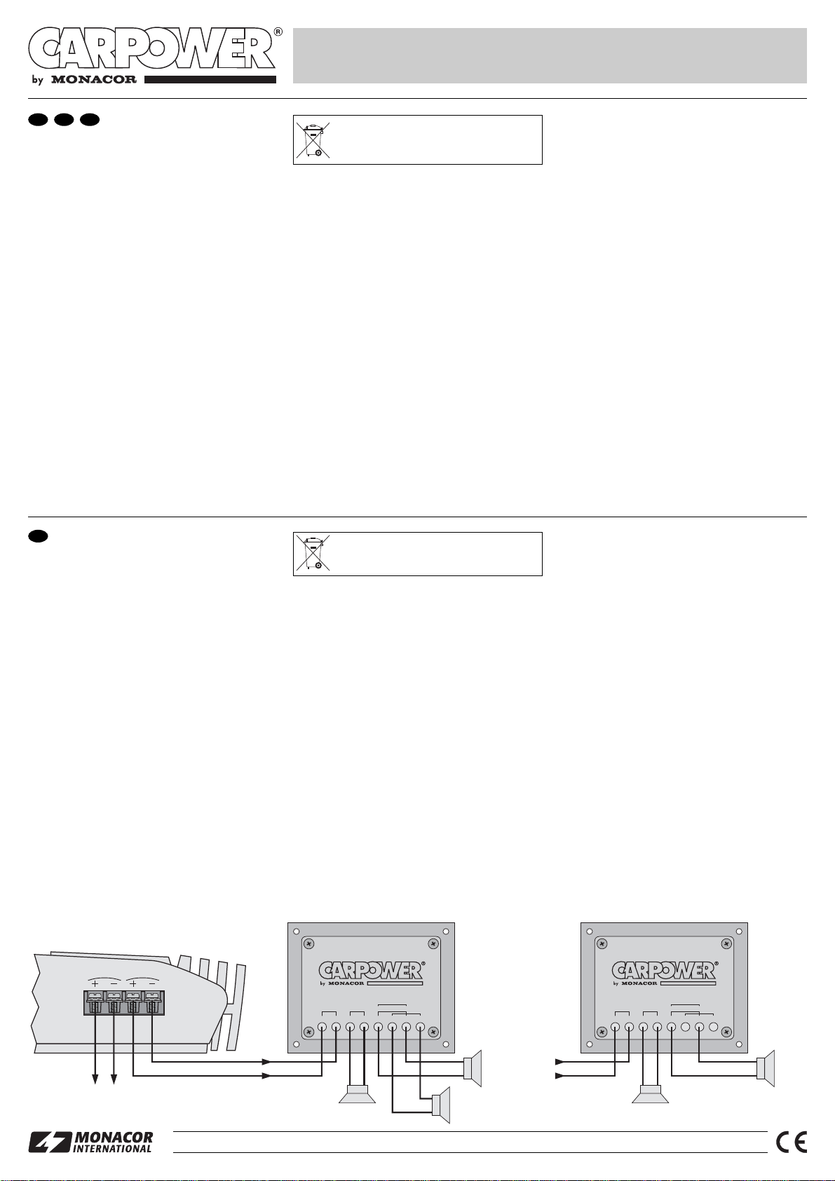
3.1 Collegamento
Il collegamento di un filtro per un canale è rappresentato
nella figura in calce. Il collegamento del secondo canale è
identico.
Per i cavi di collegamento si consiglia l’uso di cavi per
altoparlanti nei quali è contrassegnato un conduttore,
p. es. della serie SPC-… della MONACOR. Collegare il
conduttore contrassegnato sempre con il relativo polo
positivo in modo da escludere inversioni di polarità.
1) Collegare l’uscita dello stadio finale con l’ingresso IN
del filtro.
2) Collegare un tweeter 4 Ωcon i morsetti TWEETER. Per
via della bassa frequenza di taglio di 2000 Hz si dovreb-
bero impiegare solo tweeter di particolare qualità, p. es.
DT-284 di CARPOWER. Non si dovrebbero usare
tweeter con un diametro della cupola inferiore a 25 mm.
3) Collegare un woofer/midrange di 4 Ω(vedi parte destra
dell’illustrazione) oppure due woofer/midrange di 8 Ω
(parte centrale dell’illustrazione) ai morsetti WOOFER.
3.2 Eseguire le impostazioni
1) Con il commutatore X-OVER si imposta la pendenza
del filtro per un suono ottimale:
6dB/ottava o 12 dB/ottava.
Se il tweeter e il woofer/midrange per un canale sono
montati vicini (p. es. tutti e due nel fondo della macchi-
na), di solito è conveniente una pendenza di 12 dB/ott.
Nel caso di una distanza maggiore (p. es. il woofer/
midrange nello sportello, il tweeter nel triangolo della
finestra) l’impostazione a 6 dB/ott. può rendere un
suono migliore.
Per i tweeter con diametro della cupola inferiore a
28 mm, generalmente è consigliabile una pendenza di
12 dB/ott. In fin dei conti, è decisiva l’impostazione che
offre il suono migliore.
2) Con il commutatore TWEETER PHASE si imposta la
posizione delle fasi. Scegliere quella posizione in cui i
medi (intorno a 2000 Hz) offrono il suono migliore.
3) Per l’adattamento degli acuti ci si serve del cursore
TWEETER LEVEL. Nella posizione 3 dB e 6 dB gli
acuti vengono abbassati in corrispondenza.
Nella maggior parte degli impianti, la riproduzione è otti-
male se i commutatori dei due filtri si trovano in posizioni
identiche. In ogni caso occorre impostare la pendenza in
modo uguale per entrambi i filtri.
4Dati tecnici
Frequenza di taglio: . . . . . 2000 Hz
Pendenza: . . . . . . . . . . . . impostabile 6 o 12 dB/ott.
Impedenza all’uscita: . . . . 4 Ω
Potenza max. all’ingresso: 250 WMAX
Temperatura d’esercizio: . 0 – 40 °C
Dimensioni: . . . . . . . . . . . 115 x 40 x 90 mm
Con riserva di modifiche tecniche.
Se si desidera eliminare i filtri definitivamente,
consegnarli per lo smaltimento ad un’istituzio-
ne locale per il riciclaggio.
Paire de filtres de fréquences
pour installations de
Hi-Fi embarquée
1Possibilités d’utilisation
Ces filtres de fréquences 2 voies de grande qualité sont
spécialement conçus pour une utilisation dans des instal-
lations de Hi-Fi embarquée. Ils sont livrés par paire et ser-
vent à brancher ensemble un haut-parleur d’aigu 4 Ωavec
un haut-parleur de grave-médium 4 Ωou deux haut-par-
leurs de grave-médium 8 Ωpar canal stéréo. La puis-
sance d’un filtre est de 250 WMAX.
2Conseils d’utilisation et de sécurité
Les filtres répondent à la norme européenne 89/336/CEE
relative à la compatibilité électromagnétique.
●Les filtres ne sont conçus que pour une utilisation en
intérieur. Protégez-les des éclaboussures, de tout type
de projections d’eau, de l’humidité élevée et de la cha-
leur (température ambiante admissible 0 – 40 °C).
●Pour les nettoyer, utilisez un chiffon sec et doux, en
aucun cas de produits chimiques ou d’eau.
●Les filtres doivent être installés de manière fixe et de
manière professionnelle dans un endroit mécanique-
ment stable dans le véhicule pour éviter qu’ils ne se
devissent et se transforment en projectile dangereux.
●Nous déclinons toute responsabilité en cas de domma-
ges corporels ou matériels résultants si les filtres sont
utilisés dans un but autre que celui pour lequel ils ont été
conçus, s’ils ne sont pas correctement branchés, s’il y a
surcharge ou s’ils ne sont pas réparés par une personne
habilitée ; de même, la garantie deviendrait caduque.
3Fonctionnement
3.1 Branchement
Le schéma ci-dessous présente le branchement d’un filtre
pour un canal. Le branchement pour le second canal est
identique.
Il est recommandé d’utiliser des câbles haut-parleurs
comme câble de liaison où un conducteur est repéré, par
exemple de la série SPC-… de MONACOR. Reliez le con-
ducteur repéré au pôle plus correspondant pour éviter
toute inversion de polarité.
1) Reliez la sortie de l’amplificateur à l’entrée IN du filtre.
2) Reliez un haut-parleur d’aigu 4 Ωaux bornes TWEE-
TER. En raison de la fréquence de coupure basse de
2000 Hz, il convient de n’utiliser que des haut-parleurs
d’aigu de très bonne qualité, par exemple DT-284 de
CARPOWER. Des haut-parleurs d’aigu avec un
diamètre de dôme inférieur à 25 mm ne devraient pas
être utilisés.
3) Reliez aux bornes WOOFER un haut-parleur de grave-
médium 4 Ω(voir partie droite du schéma) ou deux
haut-parleurs de grave-médium 8 Ω(partie centrale du
schéma).
3.2 Réglages
1) Avec l’interrupteur X-OVER, réglez la pente du filtre
pour une tonalité optimale :
6dB/octave ou 12 dB/octave
Si le haut-parleur d’aigu et le haut-parleur de grave-
médium pour un canal sont montés à proximité l’un de
l’autre (p. ex. ensemble sur la plage arrière), une pente
de 12 dB/octave est généralement meilleure. Si la
distance est plus grande (p. ex. haut-parleur de grave-
médium dans l’habillage inférieur de la portière et haut-
parleur d’aigu dans le triangle de la vitre), un réglage
de 6 dB/octave peut donner une meilleure tonalité.
Pour des haut-parleurs d’aigu avec un diamètre de
dôme inférieure à 28 mm, une pente de 12 dB/octave
est généralement plus intéressante. En fin de compte,
c’est toujours la meilleure restitution qui est décisive
pour le réglage.
2) Avec l’interrupteur TWEETER PHASE, réglez la
phase. Sélectionnez la position de l’interrupteur pour
laquelle les fréquences médiums (env. 2000 Hz) ont la
meilleure tonalité.
3) Pour une adaptation des aigus, utilisez le potentiomètre
à glissière TWEETER LEVEL. En position 3 dB et 6 dB,
les fréquences aiguës sont diminuées en conséquence.
Sur la majorité des installations, on obtient une restitution
optimale si les interrupteurs des deux filtres sont sur la
même position. Dans tous les cas, il faut que le réglage de
la pente soit identique pour les deux filtres.
4Caractéristiques techniques
Fréquence de coupure : . . 2000 Hz
Pente : . . . . . . . . . . . . . . . commutable 6 ou 12 dB/oct.
Impédance de sortie : . . . 4 Ω
Puissance d’entrée max. : 250 WMAX
Température fonc. : . . . . . 0 – 40 °C
Dimensions : . . . . . . . . . . 115 x 40 x 90 mm
Tout droit de modification réservé.
Lorsque les filtres sont définitivement retirés du
service, vous devez les déposer dans une
usine de recyclage de proximité pour contri-
buer à leur élimination non polluante.
Copyright©by MONACOR INTERNATIONAL GmbH & Co. KG, Bremen, Germany. All rights reserved. www.carpower.com A-0390.99.01.03.2005
®
HIGH TECH
CROSSOVER NETWORK CDN-2X
Best.-Nr. 12.5500