3
1
2
AT-62...
HA + HB + H –B –
B +
C1
L-PAD
32 1
BassHigh
J1
ELECTRONICS FOR SPECIALISTS ELECTRONICS FOR SPECIALISTS ELECTRONICS FOR SPECIALISTS ELECTRONICS FOR SPECIALISTS ELECTRONICS FOR SPECIALISTS ELECTRONICS
MONACOR INTERNATIONAL GmbH & Co. KG • Zum Falsch 36 • 28307 Bremen • Germany
Copyright©by MONACOR INTERNATIONAL. All rights reserved. A-1733.99.02.01.2019
I N P U T
L 1
2m2
Bass
8 Ω
B
C 4
0µ47
150 V
MKT
High
8 Ω
C1
6µ8
150 V
MKT
L 2
0m27
C 2
3µ/150V
MKT
C 3
10µ/150V
MKT
Rx
J1
HB+
HA+
H–
H
L-PAD
1
3
2
L
1
L 2
HA + HB + H –
IN –IN +
B –
B +
C1
R
X
L-PAD
32 1
Input
C3 C2 C4
J1
D N -1218 PA X
MAX. 600 W/8 Ω
MONACOR INTERNATIONAL
ZUM FALSCH 36 · 28307 BREMEN
GERMANY
➁
➃
➀
➂
20k
20k
10k
10k
5k
5k
2k
2k
1k
1k200
500
500
100
100
50
50
Hz20
DN-1218PAX
Référence num. 12.5210
Filtre de fréquences 2 voies
pour enceintes
Cette notice s‘adresse aux non-profession-
nels avec des connaissances de base dans
la conception d‘enceintes. Veuillez lire la
présente notice avec attention avant le
fonctionnement et conservez-la pour pou-
voir vous y reporter ultérieurement.
1 Possibilités d‘utilisation
Ce filtre de fréquences est conçu pour la
conception d’une enceinte 2 voies avec une
puissance de 600W maximum. Ses propriétés
de filtrage sont prévues pour des haut-parleurs
de grave de 30cm et 38 cm.
2 Conseils importants
d‘utilisation
Le filtre de fréquences répond à toutes les di-
rectives nécessaires de l’Union européenne et
porte donc le symbole .
•
Le filtre de fréquences n’est conçu que pour
une utilisation en intérieur. Protégez-le de
tout type de projections d‘eau, des écla-
boussures et d’une humidité élevée de l’air.
La plage de température de fonctionnement
autorisée est de 0– 40°C.
•
Pour le nettoyage, utilisez un pinceau sec
et doux, en aucun cas d‘eau ou de produits
chimiques.
•
Nous déclinons toute responsabilité en cas
de dommages matériels ou corporels résul-
tants si le filtre de fréquences est utilisé dans
un but autre que celui pour lequel il a été
conçu, s‘il n‘est pas correctement branché,
s‘il y a surcharge ou s‘il n‘est pas réparé par
une personne habilitée, en outre, la garantie
deviendrait caduque.
Lorsque le filtre de fréquences est
définitivement retiré du service, vous
devez le déposer dans une usine de
recyclage adaptée pour contribuer à
son élimination non polluante.
CARTONS ET EMBALLAGE
PAPIER À TRIER
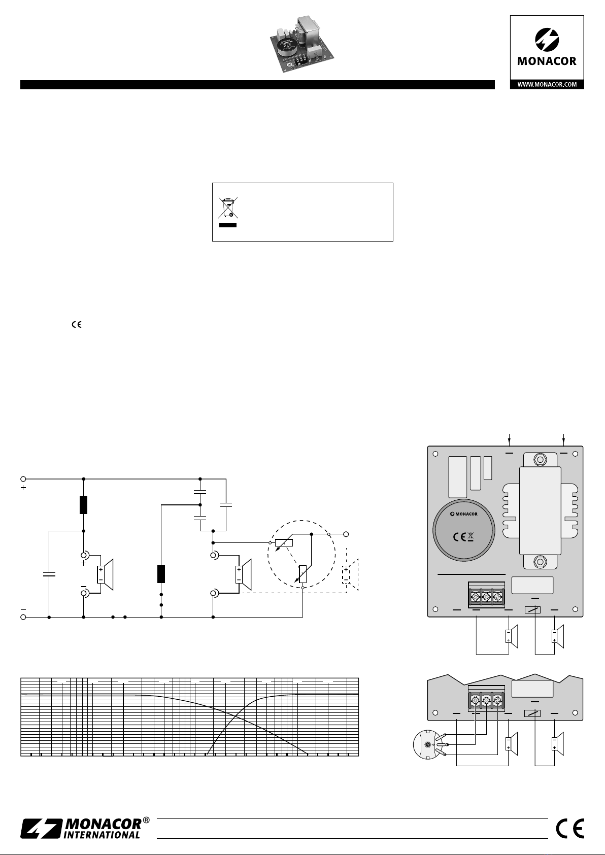
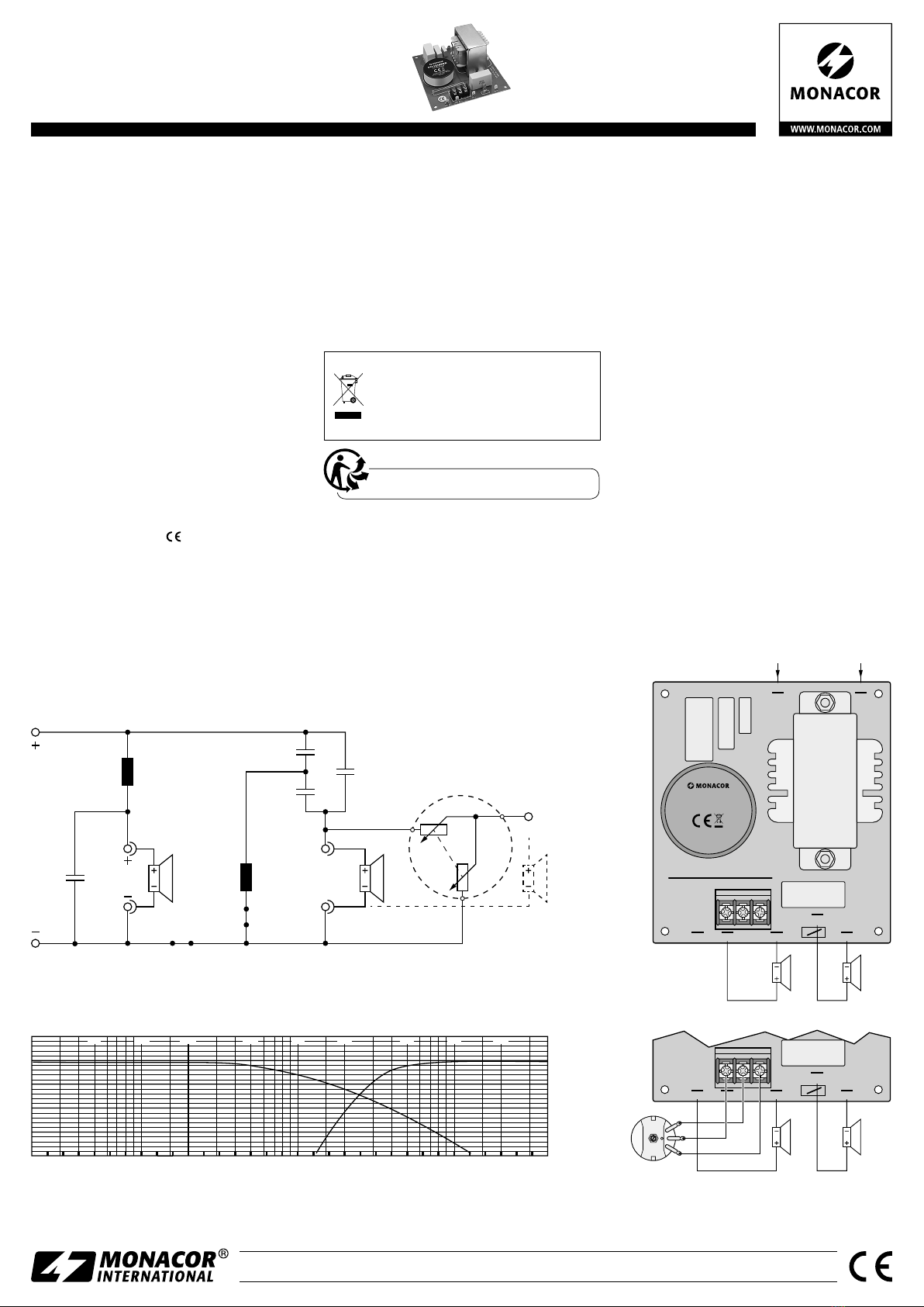
3 Branchement
1) Reliez les haut-parleurs au filtre de fré-
quences (schémas 3 et 4)
B+ et B− = haut-parleur de grave
HB+ et H− = haut-parleur d‘aigu
HA+ et H− =
haut-parleur d‘aigu, si un atté-
nuateur est utilisé (chapitre 3.1)
La polarité correcte du haut-parleur d‘aigu
dépend des haut-parleurs utilisés et de leur
positionnement dans l‘enceinte. Pour définir
correctement la polarité, il convient de faire
un test.
2) Les pins IN sont utilisés comme entrées de
signal.
3.1 Branchement d‘un atténuateur
Pour adapter de manière optimale le volume du
haut-parleur d‘aigu au volume du haut-parleur
de grave, on peut utiliser un atténuateur (par
exemple un atténuateur de la série AT-62...
de MONACOR). La barrette de branchement
L-PAD est prévue à cet effet. Vous pouvez voir
le branchement sur le schéma 4.
4 Caractéristiques techniques
Puissance d‘entrée : . . . .600 W max.
Impédance nominale :. . .8Ω
Fréquence de coupure. . .2500Hz
Haut-parleur de grave :.12 dB/octave
Haut-parleur d‘aigu : . .18 dB/octave
Dimensions : . . . . . . . . . .120 × 60 × 132 mm
Poids :. . . . . . . . . . . . . . .1,1 kg
Tout droit de modification réservé.
Français