Monacor PARL-30SPOT User manual

BEDIENUNGSANLEITUNG • INSTRUCTION MANUAL
MODE D’EMPLOI • ISTRUZIONI PER L’USO • GEBRUIKSAANWIJZING
MANUAL DE INSTRUCCIONES • INSTRUKCJA OBSŁUGI
SIKKERHEDSOPLYSNINGER • SÄKERHETSFÖRESKRIFTER • TURVALLISUUDESTA
DMX-LED-SCHEINWERFER
DMX LED SPOTLIGHT
PROJECTEUR DMX À LEDs
FARETTO DMX A LED
PARL-30SPOT Best.-Nr. 38.3100
PARL-30WASH Best.-Nr. 38.3110

2
wwwwww..iimmggssttaaggeelliinnee..ccoomm
Bevor Sie einschalten …
Wir wünschen Ihnen viel Spaß mit Ihrem neuen
Gerät von „img Stage Line“. Bitte lesen Sie diese
Bedienungsanleitung vor dem Betrieb gründlich
durch. Nur so lernen Sie alle Funktionsmöglich-
keiten kennen, vermeiden Fehlbedienungen und
schützen sich und Ihr Gerät vor eventuellen Schä-
den durch unsachgemäßen Gebrauch. Heben
Sie die Anleitung für ein späteres Nachlesen auf.
Der deutsche Text beginnt auf der Seite 4.
Before switching on …
We wish you much pleasure with your new “img
Stage Line” unit. Please read these operating
instructions carefully prior to operating the unit.
Thus, you will get to know all functions of the unit,
operating errors will be prevented, and yourself
and the unit will be protected against any damage
caused by improper use. Please keep the oper-
ating instructions for later use.
The English text starts on page 8.
Avant toute installation …
Nous vous souhaitons beaucoup de plaisir à uti-
liser cet appareil “img Stage Line”. Lisez ce mode
dʼemploi entièrement avant toute utilisation. Uni-
quement ainsi, vous pourrez apprendre lʼensem-
ble des possibilités de fonctionnement de lʼappa-
reil, éviter toute manipulation erronée et vous
protéger, ainsi que lʼappareil, de dommages
éventuels engendrés par une utilisation inadap-
tée. Conservez la notice pour pouvoir vous y
reporter ultérieurement.
La version française se trouve page 12.
Prima di accendere …
Vi auguriamo buon divertimento con il vostro
nuovo apparecchio di “img Stage Line”. Leggete
attentamente le istruzioni prima di mettere in fun-
zione lʼapparecchio. Solo così potete conoscere
tutte le funzionalità, evitare comandi sbagliati e
proteggere voi stessi e lʼapparecchio da even-
tuali danni in seguito ad un uso improprio. Con-
servate le istruzioni per poterle consultare anche
in futuro.
Il testo italiano inizia a pagina 16.
D
A
CH
GB
®
Antes de la utilización …
Le deseamos una buena utilización para su nue-
vo aparato “img Stage Line”. Por favor, lea estas
instrucciones de uso atentamente antes de hacer
funcionar el aparato. De esta manera conocerá
todas las funciones de la unidad, se prevendrán
errores de operación, usted y el aparato estarán
protegidos en contra de todo daño causado por
un uso inadecuado. Por favor, guarde las instruc-
ciones para una futura utilización.
La versión española comienza en la página 24.
Voor u inschakelt …
Wij wensen u veel plezier met uw nieuwe appa-
raat van “img Stage Line”. Lees deze gebruikers-
handleiding grondig door, alvorens het apparaat
in gebruik te nemen. Alleen zo leert u alle functies
kennen, vermijdt u foutieve bediening en behoedt
u zichzelf en het apparaat voor eventuele schade
door ondeskundig gebruik. Bewaar de handlei-
ding voor latere raadpleging.
De Nederlandstalige tekst vindt u op pagina 20.
Przed uruchomieniem …
Życzymy zadowolenia z nowego produktu “img
Stage Line”. Dzięki tej instrukcji obsługi będą
państwo w stanie poznać wszystkie funkcje tego
urządzenia. Stosując się do instrukcji unikną
państwo błędów i ewentualnego uszkodzenia
urządzenia na skutek nieprawidłowego użytko-
wania. Prosimy zachować instrukcję.
Tekst polski zaczyna się na stronie 28.
Før du tænder …
Tillykke med dit nye “img Stage Line” produkt.
Læs sikkerhedsanvisningerne nøje før ibrugtag-
ning, for at beskytte Dem og enheden mod ska-
der, der skyldes forkert brug. Gem manualen til
senere brug.
Sikkerhedsanvisningerne findes på side 32.
Innan du slår på enheten …
Vi önskar dig mycket glädje med din nya “img
Stage Line” produkt. Läs igenom säkerhetsföre-
skrifterna innan enheten tas i bruk för att undvika
skador till följd av felaktig hantering. Behåll
instruktionerna för framtida bruk.
Säkerhetsföreskrifterna återfinns på sidan 32.
Ennen kytkemistä …
Toivomme Sinulle paljon miellyttäviä hetkiä uuden
“img Stage Line” laitteen kanssa. Ennen laitteen
käyttöä Sinua huolellisesti tutustumaan turvalli-
suusohjeisiin. Näin vältyt vahingoilta, joita virheel-
linen laitteen käyttö saattaa aiheuttaa. Ole hyvä ja
säilytä käyttöohjeet myöhempää tarvetta varten.
Turvallisuusohjeet löytyvät sivulta 33.
F
B
CH
I
ENL
PL DK
SFIN

3
DMX OUT
3
12
DMX IN
ONLY FOR
REMOTE
CONTROL
DMX
ADDRESS
SETTING
123451
678 9
10 11 12
13
14
15

Bitte klappen Sie die Seite 3 heraus. Sie sehen
dann immer die beschriebenen Bedienelemente
und Anschlüsse.
1 Übersicht der Bedienelemente und
Anschlüsse
1.1 Scheinwerfer
1Feststellschrauben für den Montagebügel (9)
2Anschlussbuchse für die Fernbedienung LC-3
3DMX-Signal-Ausgang (3-pol. XLR) zum Anschluss
an den DMX-Eingang eines weiteren DMX-Lichtef-
fektgeräts;
1 = Masse, 2 = DMX
-
, 3 = DMX+
4DMX-Signal-Eingang (3-pol. XLR);
1 = Masse, 2 = DMX
-
, 3 = DMX+
5Taste für die DMX-Adresseneinstellung
(siehe Kapitel 7.2)
6Netzkabel zum Anschluss an eine Steckdose
(230 V~/50 Hz)
7Montageplatte zur Befestigung an einer Wand oder
Decke
8Schraube für die Montageplatte
9Montagebügel
10 Gehäusedeckel mit Kunststoffscheibe
11 Feststellschraube für die Verriegelung (12)
12 Verriegelung für den Gehäusedeckel
1.2 Fernbedienung LC-3
Die Fernbedienung ist als Zubehör erhältlich und
gehört nicht zum Lieferumfang des Scheinwerfers.
13 Taste STAND BY für die Funktion Blackout (Licht
aus)
14 Taste FUNCTION zur Auswahl verschiedener
Lichtwechselfunktionen in Abhängigkeit von dem
mit der Taste MODE gewählten Betriebsmodus
15 Taste MODE zum Umschalten zwischen
Sound-Modus 1 (LED leuchtet nicht)
Manual-Modus (LED leuchtet)
Sound-Modus 2 (LED blinkt langsam)
Auto-Modus (LED blinkt schnell)
Hinweis: Zur Steuerung über die Fernbedienung darf
am Eingang DMX IN (4) kein DMX-Signal anliegen.
2 Hinweise für den sicheren Gebrauch
Der Scheinwerfer entspricht allen erforderlichen Richt-
linien der EU und ist deshalb mit gekennzeichnet.
Beachten Sie auch unbedingt die folgenden Punkte:
Verwenden Sie den Scheinwerfer nur im Innen-
bereich und schützen Sie ihn vor Tropf- und Spritz-
wasser, hoher Luftfeuchtigkeit und Hitze (zulässiger
Einsatztemperaturbereich 0 – 40 °C).
Nehmen Sie den Scheinwerfer nicht in Betrieb oder
ziehen Sie sofort den Netzstecker aus der Steckdose,
1. wenn sichtbare Schäden am Gerät oder an der
Netzanschlussleitung vorhanden sind,
2. wenn nach einem Sturz oder Ähnlichem der Ver-
dacht auf einen Defekt besteht,
3. wenn Funktionsstörungen auftreten.
Geben Sie das Gerät in jedem Fall zur Reparatur in
eine Fachwerkstatt.
Eine beschädigte Netzanschlussleitung darf nur
durch eine Fachwerkstatt ersetzt werden.
Ziehen Sie den Netzstecker nie an der Zuleitung aus
der Steckdose, fassen Sie immer am Stecker an.
Verwenden Sie für die Reinigung nur ein trockenes,
weiches Tuch, niemals Wasser oder Chemikalien.
Wird der Scheinwerfer zweckentfremdet, nicht sicher
montiert, falsch bedient oder nicht fachgerecht repa-
riert, kann keine Haftung für daraus resultierende
Sach- oder Personenschäden und keine Garantie für
den Scheinwerfer übernommen werden.
3 Einsatzmöglichkeiten
Der Scheinwerfer ist für den Einsatz auf Bühnen, in Dis-
kotheken und Partyräumen oder zu Dekorationszwe-
cken geeignet. Er erzeugt farbiges Licht über superhelle
5-mm-LEDs, die in Blau, Rot und Grün leuchten:
PARL-30SPOT: 90 LEDs, Abstrahlwinkel 20°
PARL-30WASH: 91 LEDs, Abstrahlwinkel 120°
Es sind auch musikgesteuerte Farbwechsel, langsame
Farbüberblendungen und Stroboskop-Effekte möglich.
Der Scheinwerfer ist für die Steuerung über ein
DMX-Lichtsteuergerät ausgelegt (4 DMX-Steuerka-
näle), kann aber auch ohne Steuergerät oder mit der
als Zubehör erhältlichen Fernbedienung LC-3 betrie-
ben werden.
Soll der Scheinwerfer endgültig aus dem
Betrieb genommen werden, übergeben Sie
ihn zur umweltgerechten Entsorgung einem
örtlichen Recyclingbetrieb.
WARNUNG Der Scheinwerfer wird mit lebensge-
fährlicher Netzspannung (230 V~) ver-
sorgt. Nehmen Sie deshalb niemals
selbst Eingriffe am Gerät vor und ste-
cken Sie nichts durch die Lüftungs-
öffnungen! Es besteht die Gefahr eines
elektrischen Schlages.
4
D
A
CH

4 Montage
Platzieren Sie das Gerät immer so, dass im Betrieb
eine ausreichende Luftzirkulation gewährleistet ist.
Die Lüftungsöffnungen am Gehäuse dürfen auf kei-
nen Fall abgedeckt werden (z. B. durch Vorhänge).
Der Abstand zum angestrahlten Objekt sollte min-
destens 10 cm betragen.
1) Den Montagebügel (9) mit den beiden Knebel-
schrauben (1) am Scheinwerfergehäuse fest-
schrauben.
2) Den Scheinwerfer über den Montagebügel (9) be-
festigen, z. B. mit einer stabilen Montageschraube
oder einer Lichtstrahler-Halterung (C-Haken) an
einer Traverse.
Soll der Scheinwerfer an einer Decke oder Wand
befestigt werden, die Montageplatte (7) an den
Montagebügel nach der Abbildung 1 festschrau-
ben. Die Montageplatte mit dem Scheinwerfer an
geeignerter Stelle der Decke bzw. Wand fest-
schrauben.
3) Zum Ausrichten des Scheinwerfers die zwei Fest-
stellschrauben (1) am Montagebügel lösen. Die ge-
wünschte Neigung des Scheinwerfers einstellen
und die Schrauben wieder fest anziehen.
Ist der Scheinwerfer an der Montageplatte (7)
festgeschraubt, ggf. die Schraube (8) etwas lösen,
den Montagebügel (9) wie gewünscht drehen und
die Schraube wieder festziehen.
5 Inbetriebnahme
Zum Einschalten des Scheinwerfers den Stecker des
Netzkabels (6) in eine Steckdose (230 V~/50 Hz) ste-
cken, zum Ausschalten ihn wieder herausziehen.
Um einen besseren Bedienkomfort zu erhalten, ist
es empfehlenswert, den Scheinwerfer an eine Steck-
dose anzuschließen, die sich über einen Lichtschalter
ein- und ausschalten lässt.
Vorsicht: Der Scheinwerfer darf nicht uber einen Dim-
mer an die Netzspannung angeschlossen werden!
6 Betrieb ohne Steuergerät
Empfängt der Scheinwerfer kein DMX-Steuersignal,
wechselt er selbstständig mit langsamen Überblen-
dungen die Farben.
Läuft Musik mit deutlichem Rhythmus im Bassbe-
reich in ausreichender Lautstärke, wechselt der
Scheinwerfer, gesteuert über ein internes Mikrofon,
die Farbe im Takt der Musik. Sollte die Musiksteuerung
nicht optimal funktionieren, die Lautstärke erhöhen
oder den Abstand zwischen Schallquelle und Schein-
werfer verringern.
6.1 Zusammenschalten mehrerer Scheinwerfer
Es lassen sich mehrere PARL-30SPOT und PARL-
30WASH (auch gemischt) zusammenschalten, um so
synchron die Farben zu wechseln oder über das
interne Mikrofon des Hauptgerätes alle weiteren
Nebengeräte im gleichen Rhythmus zu steuern.
Dazu den Anschluss DMX OUT (3) des Hauptgerä-
tes über ein 3-poliges XLR-Kabel (z. B. Serie MEC-...
oder MECN-... aus dem Sortiment von „img Stage
Line“) mit dem Anschluss DMX IN (4) des ersten
Nebengerätes verbinden.
Den Anschluss DMX OUT des ersten Nebengerä-
tes mit dem Anschluss DMX IN des zweiten Nebenge-
rätes verbinden usw.
6.2 Fernbedienung über LC-3
Über die als Zubehör erhältliche Fernbedienung LC-3
können zusätzlich zu der Musiksteuerung verschie-
dene Funktionen gesteuert werden.
1) Die Fernbedienung an die Buchse REMOTE CON-
TROL (2) anschließen.
2) Am Eingang DMX IN (4) darf kein DMX-Signal an-
liegen.
3) Über den Ausgang DMX OUT (3) können weitere
PARL-30SPOT oder PARL-30WASH angeschlos-
sen werden (Kapitel 6.1), um diese über die
Fernbedienung gemeinsam mit dem Hauptgerät zu
steuern.
4) Mit der Taste STAND BY (13) lässt sich die Funktion
Blackout ein- und ausschalten. Bei eingeschalteter
Funktion wird das Licht abgeblendet und die LED
neben der Taste leuchtet.
5) Mit der Taste MODE (15) den Betriebsmodus wählen:
a) Nach dem Einschalten des Scheinwerfers ist der
Modus SOUND 1 aktiviert. Die LED neben der
Taste MODE leuchtet nicht. Bei gedrückt gehal-
tener Taste FUNCTION (14) wird ein musik-
abhängiger Stroboskop-Effekt erzeugt. Bei je-
dem neuen Drücken der Taste wechselt dieser
zwischen weißem Licht, wechselndem farbigem
Licht (bei mehreren Scheinwerfern als kurze
Sequenz mit nur einem Blitz pro Scheinwerfer;
die Farbe ist bei allen Scheinwerfern gleich) und
wechselndem farbigem Licht mit unterschiedli-
chen Farben bei mehreren Scheinwerfern.
WARNUNG Der Scheinwerfer muss fachgerecht
und sicher montiert werden. Wird er
an einer Stelle installiert, unter der
sich Personen aufhalten können,
muss er zusätzlich gesichert werden
(z. B. durch ein Fangseil am Monta-
gebügel; das Fangseil so befestigen,
dass der Fallweg des Gerätes nicht
mehr als 20 cm betragen kann).
WARNUNG Blicken Sie nicht direkt in die LEDs, das
kann zu Augenschäden führen.
Beachten Sie, dass sehr schnelle Licht-
wechsel bei fotosensiblen Menschen
und Epileptikern epileptische Anfälle
auslösen können!
5
D
A
CH

b) Zum Umschalten auf den Modus MANUAL die
Taste MODE einmal drücken. Die LED neben
der Taste leuchtet. Mit der Taste FUNCTION
kann jetzt eine der folgenden Farben ausge-
wählt werden:
Weiß, Rot, Blau, Violett, Orange, Grün, Gelb,
Magenta, Cyan
c) Zum Umschalten auf den Modus SOUND 2 die
Taste MODE ein weiteres Mal drücken. Die LED
neben der Taste blinkt langsam. Mit der Taste
FUNCTION kann durch wiederholtes Drücken
zwischen fünf verschiedenen musikgesteuerten
Farbwechseloptionen und Sequenzen gewählt
werden. Diese Optionen sind nur mit mehreren
zusammengeschalteten Scheinwerfern sinnvoll.
d) Zum Umschalten auf den Modus AUTO die
Taste MODE ein weiteres Mal drücken. Die LED
neben der Taste blinkt schnell. In dieser
Betriebsart werden die Farben automatisch
durch Überblenden gewechselt. Laufende Musik
hat hierauf keinen Einfluss. Mit der Taste
FUNCTION kann durch wiederholtes Drücken
zwischen drei verschiedenen Überblendge-
schwindigkeiten gewählt werden.
Zum Zurückschalten auf den Modus SOUND 1
die Taste MODE erneut drücken.
7 Bedienung über ein Lichtsteuergerät
Zur Bedienung über ein Lichtsteuergerät mit DMX512-
Protokoll (z. B. DMX-1440 oder DMX-510USB von
„img Stage Line“) verfügt der Scheinwerfer über vier
Steuerkanäle. Die Funktionen der Kanäle und die
DMX-Werte finden Sie im Kapitel 9.1.
7.1 Anschluss
Als DMX-Schnittstelle besitzt der Scheinwerfer 3-po-
lige XLR-Anschlüsse mit folgender Kontaktbelegung:
1 = Masse, 2 = DMX
-
, 3 = DMX+
Zum Anschluss sollten spezielle Kabel für hohen
Datenfluss verwendet werden. Normale abgeschirmte
Mikrofonkabel mit einem Leitungsquerschnitt von min-
destens 2 × 0,22 mm2und möglichst geringer Kapazi-
tät sind nur bei einer Gesamtkabellänge bis 100 m zu
empfehlen. Bei Leitungslängen ab 150 m wird das Zwi-
schenschalten eines DMX-Aufholverstärkers empfoh-
len (z. B. SR-103DMX von „img Stage Line“).
1) Den DMX-Eingang (4) mit dem DMX-Ausgang des
Lichtsteuergerätes verbinden.
2) Den DMX-Ausgang (3) mit dem DMX-Eingang des
nächsten Lichteffektgerätes verbinden. Dessen
Ausgang wieder mit dem Eingang des nachfolgen-
den Gerätes verbinden usw., bis alle Lichteffektge-
räte in einer Kette angeschlossen sind.
3) Den DMX-Ausgang des letzten DMX-Geräts der
Kette mit einem 120-Ω-Widerstand (> 0,3 W) ab-
schließen: An die Pins 2 und 3 eines XLR-Steckers
den Widerstand anlöten und den Stecker in den
DMX-Ausgang stecken oder einen entsprechenden
Abschlussstecker (z. B. DLT-123 von „img Stage
Line“) verwenden.
7.2 Startadresse einstellen
Um den Scheinwerfer mit einem Lichtsteuergerät
bedienen zu können, muss die DMX-Startadresse für
den 1. DMX-Kanal eingestellt werden. Ist z. B. am
Steuergerät die Adresse 17 zum Steuern der Farbe
Rot vorgesehen, am Scheinwerfer die Startadresse 17
einstellen. Die anderen Funktionen des Scheinwerfers
(Grün, Blau, Dimmer) sind dann automatisch den drei
folgenden Kanälen (in diesem Beispiel 18 – 20) zuge-
ordnet. Als nächstmögliche Startadresse für das fol-
gende DMX-gesteuerte Gerät könnte dann bei diesem
Beispiel die Adresse 21 verwendet werden.
Zum Einstellen der Adresse stehen die folgenden zwei
Methoden zur Verfügung:
7.2.1 Automatische Adresseneinstellung
Diese Methode ist sinnvoll, wenn mehrere PARL-
30SPOT oder PARL-30WASH verwendet werden und
deren Adressen im unteren Bereich liegen sollen:
1) Den DMX-Eingang (4) des ersten Scheinwerfers
vom Steuergerät trennen oder das Steuergerät
ausschalten, sodass kein DMX-Signal am Eingang
des Scheinwerfers anliegt.
2) Die Taste DMX ADDRESS SETTING (5) am ersten
Scheinwerfer fünf Sekunden lang drücken. Der
Scheinwerfer und die an ihm angeschlossenen
Scheinwerfer werden dann dunkel.
3) Die Verbindung zum Steuergerät wiederherstellen
bzw. das Steuergerät wiedereinschalten.
Die Startadresse des ersten Scheinwerfers ist nun auf
1 eingestellt, die Startadressen der folgenden Schein-
werfer auf 5, 9, 13 usw.
7.2.2 Adresseneinstellung über das Steuergerät
Mit dieser Methode kann einem Scheinwerfer auf ein-
fache Weise eine beliebige Startadresse zugewiesen
werden:
1) Am Steuergerät den DMX-Wert des Kanals, der der
einzustellenden Startadresse entspricht, auf das
Maximum (255) stellen. Die Werte aller anderen
DMX-Kanäle auf Null stellen. Soll z. B. die Start-
adresse 17 eingestellt werden, den Kanal 17 am
Steuerpult voll aufziehen und alle anderen Kanäle
auf Null stellen.
2) Bei allen Scheinwerfern, die diese Startadresse
erhalten sollen, kurz die Taste DMX ADDRESS
SETTING (5) drücken.
Diese Bedienschritte wiederholen, bis jeder Schein-
werfer seine Adresse erhalten hat.
6
D
A
CH

7.3 Steuerung mit dem LED-4C
Das Gerät LED-4C von „img Stage Line“ ist ein einfach
zu bedienendes Steuerpult speziell für diese LED-
Scheinwerfer. Es verfügt über 4 Kanäle, sodass alle
daran angeschlossenen Scheinwerfer nur synchron
gesteuert werden können.
Die Startadresse der Scheinwerfer auf 1 oder auf
ein Vielfaches von 4 + 1 (5, 9, 13, … max. 61) einstel-
len, Kapitel 7.2.1. Genaueres zur Bedienung ent-
nehmen Sie bitte der Anleitung zum LED-4C.
8 Scheinwerfer säubern
Die Kunststoffscheibe des Scheinwerferdeckels (10)
sollte in regelmäßigen Abständen, je nach Verschmut-
zung durch Staub, Rauch oder andere Schmutzparti-
kel, von außen und ggf. auch von innen gereinigt wer-
den. Nur dann kann das Licht in maximaler Helligkeit
abgestrahlt werden.
1) Zum Säubern ein weiches, sauberes Tuch und ein
mildes Reinigungsmittel verwenden. Anschließend
die Kunststoffscheibe trocken wischen.
2) Um die Scheibe von innen reinigen zu können,
muss der Scheinwerferdeckel (10) abgenommen
werden.
VORSICHT! Vor dem Öffnen des Scheinwerfers
unbedingt den Netzstecker aus der Steckdose zie-
hen.
a) Die Feststellschraube (11) lösen und den Riegel
(12) nach hinten schieben.
b) Den Scheinwerferdeckel ein Stück gegen den
Uhrzeigersinn drehen, sodass er ausrastet und
abgenommen werden kann.
c) Die Scheibe von innen reinigen und den Schein-
werfer in umgekehrter Reihenfolge wieder zu-
sammensetzen.
9 Technische Daten
Stromversorgung: . . . . . 230 V~/50 Hz
Leistungsaufnahme: . . . 10 VA
Leuchtmittel
PARL-30SPOT: . . . . 90 superhelle 5-mm-LEDs
24 rote, 33 grüne, 33 blaue,
Abstrahlwinkel 20°
PARL-30WASH: . . . . 91 superhelle 5-mm-LEDs
31 rote, 30 grüne, 30 blaue,
Abstrahlwinkel 120°
Einsatztemperatur: . . . . 0 – 40 °C
Abmessungen: . . . . . . . Ø 120 mm × 120 mm
Gewicht: . . . . . . . . . . . . 1 kg
Kabellänge: . . . . . . . . . 1,2 m
9.1 DMX-Kanäle
Änderungen vorbehalten.
DMX-Wert Funktion
Kanal 1: Rot-Anteil
0 – 255 Helligkeit Rot
Kanal 2: Grün-Anteil
0 – 255 Helligkeit Grün
Kanal 3: Blau-Anteil
0 – 255 Helligkeit Blau
Kanal 4: Dimmer/Stroboskop/Musik
0–7 LEDs aus
8 – 190 Dimmer
191 – 200 musikgesteuerter Farbwechsel
über das integrierte Mikrofon
201 – 247 Stroboskop-Effekt: langsam →schnell
248 – 255 volle Helligkeit
7
D
A
CH
Diese Bedienungsanleitung ist urheberrechtlich für MONACOR
®
INTERNATIONAL GmbH & Co. KG geschützt.
Eine Reproduktion für eigene kommerzielle Zwecke – auch auszugsweise – ist untersagt.

Please unfold page 3. Then you will always see the
operating elements and connections described.
1 Operating Elements and Connections
1.1 Spotlight
1Locking screws for the mounting bracket (9)
2Connection jack for the remote control LC-3
3DMX signal output (3-pole, XLR) for connection to
the DMX input of another DMX light effect unit;
1 = ground, 2 = DMX
-
, 3 = DMX+
4DMX signal input (3-pole, XLR);
1 = ground, 2 = DMX
-
, 3 = DMX+
5Button for adjusting the DMX address
(see chapter 7.2)
6Mains cable for connection to a socket
(230 V~/50 Hz)
7Mounting plate for fixing the spotlight to a wall or
ceiling
8Screw for the mounting plate
9Mounting bracket
10 Housing cover with plastic pane
11 Locking screw for the latch (12)
12 Latch for the housing cover
1.2 Remote control LC-3
The remote control is available as an accessory and
not supplied with the LED spotlight.
13 Button STAND BY for the function Blackout (light
off)
14 Button FUNCTION for selecting various light
changing functions depending on the operating
mode selected with the button MODE
15 Button MODE for switching over between
Sound mode 1 (LED off)
Manual mode (LED on)
Sound mode 2 (LED flashing slowly)
Auto mode (LED flashing rapidly)
Note: For control via the remote control, there must be
no DMX signal at the input DMX IN (4).
2 Safety Notes
The spotlight corresponds to all required directives of
the EU and is therefore marked with .
Please observe the following items in any case:
The spotlight is suitable for indoor use only. Protect
it against dripping water and splash water, high air
humidity, and heat (admissible ambient temperature
range 0 – 40 °C).
Do not operate the spotlight or immediately discon-
nect the mains plug from the mains socket
1. in case of visible damage to the unit or to the
mains cable,
2. if a defect might have occurred after the unit was
dropped or suffered a similar accident,
3. if malfunctions occur.
In any case the unit must be repaired by skilled per-
sonnel.
A damaged mains cable must be replaced by skilled
personnel only.
Never pull the mains cable for disconnecting the
mains plug from the mains socket, always seize the
plug.
For cleaning only use a dry, soft cloth, never use
chemicals or water.
No guarantee claims for the spotlight and no liability
for any resulting personal damage or material
damage will be accepted if the spotlight is used for
other purposes than originally intended, if it is not
safely mounted or correctly operated, or not repaired
in an expert way.
Important for U. K. Customers!
The wires in this mains lead are coloured in accord-
ance with the following code:
green/yellow = earth
blue = neutral
brown = live
As the colours of the wires in the mains lead of this
appliance may not correspond with the coloured
markings identifying the terminals in your plug, pro-
ceed as follows:
1. The wire which is coloured green and yellow must
be connected to the terminal in the plug which is
marked with the letter E or by the earth symbol ,
or coloured green or green and yellow.
2. The wire which is coloured blue must be con-
nected to the terminal which is marked with the
letter N or coloured black.
3. The wire which is coloured brown must be con-
nected to the terminal which is marked with the
letter L or coloured red.
Warning – This appliance must be earthed.
If the spotlight is to be put out of operation
definitively, take it to a local recycling plant for
a disposal which is not harmful to the envi-
ronment.
WARNING The spotlight is supplied with hazardous
mains voltage (230 V~). Leave servic-
ing to skilled personnel only and do not
insert anything into the air vents, other-
wise you will risk an electric shock!
8
GB

3 Applications
This spotlight is suited for applications on stage, in dis-
cothèques and party rooms or for decoration pur-
poses. It creates coloured light via extra bright 5 mm
LEDs in blue, red, and green:
PARL-30SPOT: 90 LEDs, beam angle: 20°
PARL-30WASH: 91 LEDs, beam angle: 120°
Music-controlled colour changes, gradual transitions
from one colour to another, and stroboscopic effects
will be possible.
The spotlight is designed for control via a DMX light
controller (4 DMX control channels), however, it can
also be operated without a controller or with the remote
control LC-3 available as an accessory.
4 Mounting
Always place the spotlight in such a way that a suf-
ficient air circulation will be ensured during opera-
tion. Never cover the air vents of the housing (e. g.
by curtains).
The minimum distance to the illuminated object
should be 10 cm.
1) Fasten the mounting bracket (9) to the housing of
the spotlight by means of the two knob screws (1).
2) Fasten the spotlight via the mounting bracket (9),
e. g. with a stable mounting screw or a support for
lighting units (C-hook) on a cross bar.
For mounting the spotlight on a ceiling or a wall,
screw the mounting plate (7) to the mounting brack-
et according to figure 1. Find a suitable place on the
ceiling or wall and screw on the mounting plate with
the spotlight.
3) To adjust the spotlight, release the two locking
screws (1) at the mounting bracket. Adjust the de-
sired inclination of the spotlight, then retighten the
screws.
If the spotlight is screwed to the mounting plate
(7), slightly release the screw (8), if necessary, turn
the mounting bracket (9) as desired, then retighten
the screw.
5 Setting the Spotlight into Operation
To switch on the spotlight, connect the plug of the
mains cable (6) to a socket (230 V~/50 Hz); to switch it
off, disconnect it.
For a more convenient operation, it is recom-
mended to connect the spotlight to a mains socket
which is switched on and off via a light switch.
Caution: Do not connect the spotlight to the mains
voltage via a dimmer!
6 Operation without Controller
If the spotlight does not receive any DMX control sig-
nal, it will automatically change colours by gradual
transition from one colour to another.
If music is played at sufficient volume with a clear
rhythm in the bass range, the spotlight will change
colours to the beat of the music, controlled via an inter-
nal microphone. If the music control should fail to op-
erate optimally, increase the volume or reduce the dis-
tance between the sound source and the spotlight.
6.1 Interconnecting several spotlights
Several PARL-30SPOT and PARL-30WASH units
(also a combination of both) may be interconnected in
order to change colours in sync or to control all slave
units to the same rhythm via the internal microphone of
the master unit.
For this purpose, connect the output DMX OUT (3)
of the master unit via a 3-pole XLR cable (e. g. series
MEC-… or MECN-… from the product range of
“img Stage Line”) to the input DMX IN (4) of the first
slave unit.
Connect the output DMX OUT of the first slave unit
to the input DMX IN of the second slave unit, etc.
6.2 Remote control via LC-3
The remote control LC-3 available as an accessory
allows to control various functions in addition to the
music control.
1) Connect the remote control to the jack REMOTE
CONTROL (2).
2) There must be no DMX signal at the input DMX IN
(4).
3) Via the output DMX OUT (3), further PARL-30SPOT
or PARL-30WASH units may be connected
(chapter 6.1) in order to control them together
with the master unit via the remote control.
4) The button STAND BY (13) allows to activate/
deactivate the function Blackout. With the function
WARNING Never look directly into the LEDs; this
may cause eye damage.
Please note that fast changes in
lighting, e. g. flashing light, may trigger
epileptic seizures with photosensitive
persons or persons with epilepsy!
WARNING Mount the spotlight safely and ex-
pertly. If the spotlight is installed at a
place where people may walk or sit
under it, additionally secure it (e. g.
by a safety rope fixed to the mount-
ing bracket; fasten the safety rope in
such a way that, even in the event of
a fall, the maximum falling distance
of the spotlight will not exceed
20 cm).
9
GB

activated, the light will be off and the LED next to
the button will light up.
5) Select the operating mode with the button MODE
(15).
a) After switching on the spotlight, the mode
SOUND 1 will be activated. The LED next to the
button MODE will not light up. When the button
FUNCTION (14) is kept pressed, a music-
dependent stroboscopic effect will be created.
Each time the button is pressed again, this effect
will change between white light, changing
coloured light (in case of several spotlights as a
short sequence of only one flash per spotlight;
with the same colour for all spotlights), and
changing coloured light with different colours in
case of several spotlights.
b) To switch to the mode MANUAL, press the but-
ton MODE once. The LED next to the button will
light up. Use the button FUNCTION to select one
of the following colours:
white, red, blue, purple, orange, green, yellow,
magenta, cyan
c) To switch to the mode SOUND 2, press the but-
ton MODE once again. The LED next to the but-
ton will flash slowly. A selection of five music-
controlled colour change options and sequences
is available when the button FUNCTION is
pressed repeatedly. These options, however,
only make sense when several spotlights have
been interconnected.
d) To switch to the mode AUTO, press the button
MODE once again. The LED next to the button
will flash rapidly. In this operating mode, the
colours will change automatically by transition
from one colour to another. Any music played at
this stage will not affect this mode. A selection of
three transition speeds is available when the
button FUNCTION is pressed repeatedly.
To return to the mode SOUND 1, press the but-
ton MODE once again.
7 Operation via a Light Controller
For operation via a light controller with DMX512 proto-
col (e. g. DMX-1440 or DMX-510USB by “img Stage
Line”), the spotlight is equipped with four control chan-
nels. The functions of the channels and the DMX
values can be found in chapter 9.1.
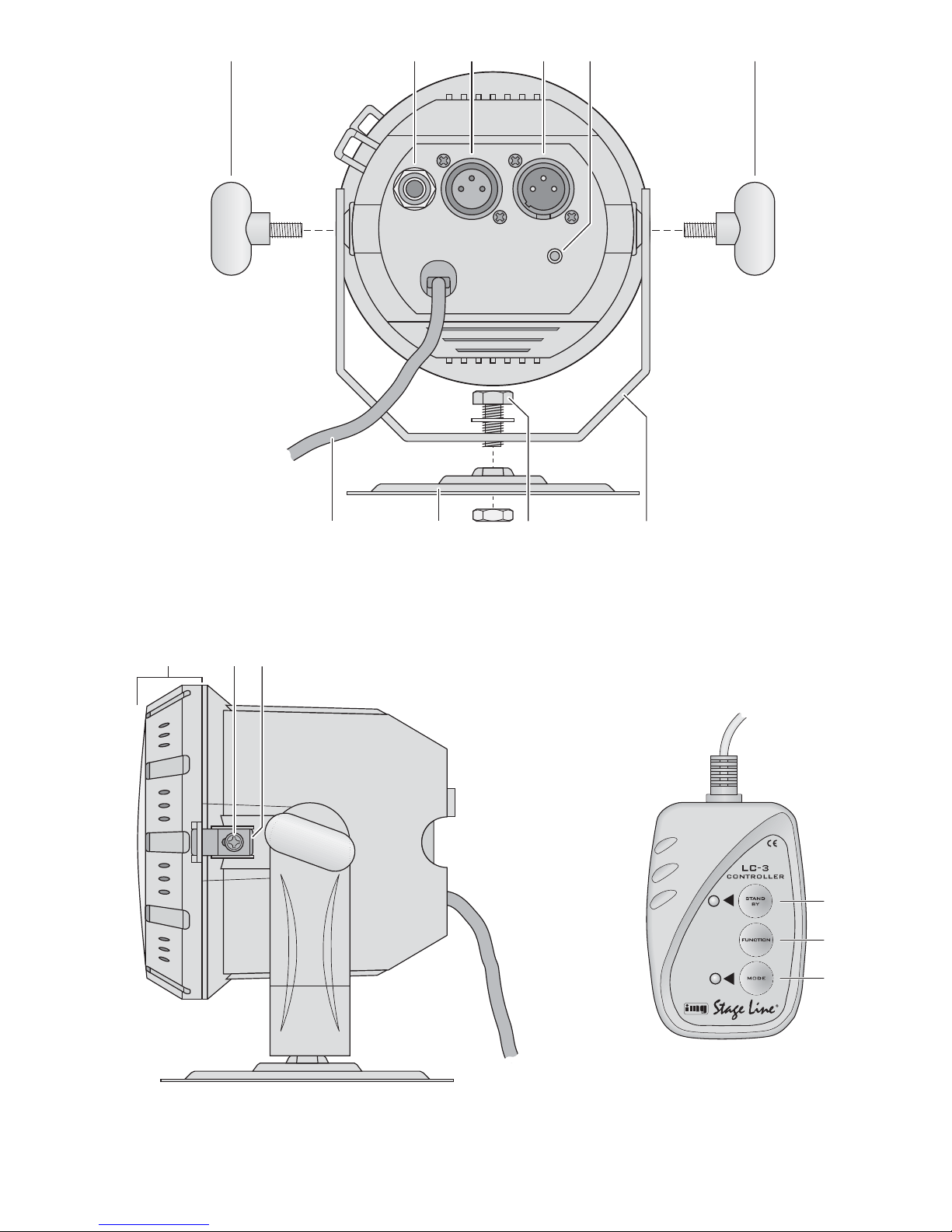
7.1 Connection
As a DMX interface, the spotlight is provided with
3-pole XLR jacks of the following pin configuration:
1 = ground, 2 = DMX
-
, 3 = DMX+
For connection, special cables for high data flow
should be used. Microphone cables with standard
screening and a minimum cross section of 2 × 0.22 mm2
and with a capacity as low as possible can only be
recommended for a total cable length of up to 100 m.
For cable lengths exceeding 150 m it is recommended
to insert a DMX level matching amplifier (e. g. SR-
103DMX by “img Stage Line”).
1) Connect the DMX input (4) to the DMX output of the
light controller.
2) Connect the DMX output (3) to the DMX input of the
following light effect unit; connect its output again to
the input of the following unit, etc. until all light effect
units have been connected in a chain.
3) Terminate the DMX output of the last DMX unit in
the chain with a 120 Ω resistor (> 0.3 W): Solder the
resistor to the pins 2 and 3 of an XLR plug and con-
nect the plug to the DMX output or use a corre-
sponding terminating plug (e. g. DLT-123 by “img
Stage Line”).
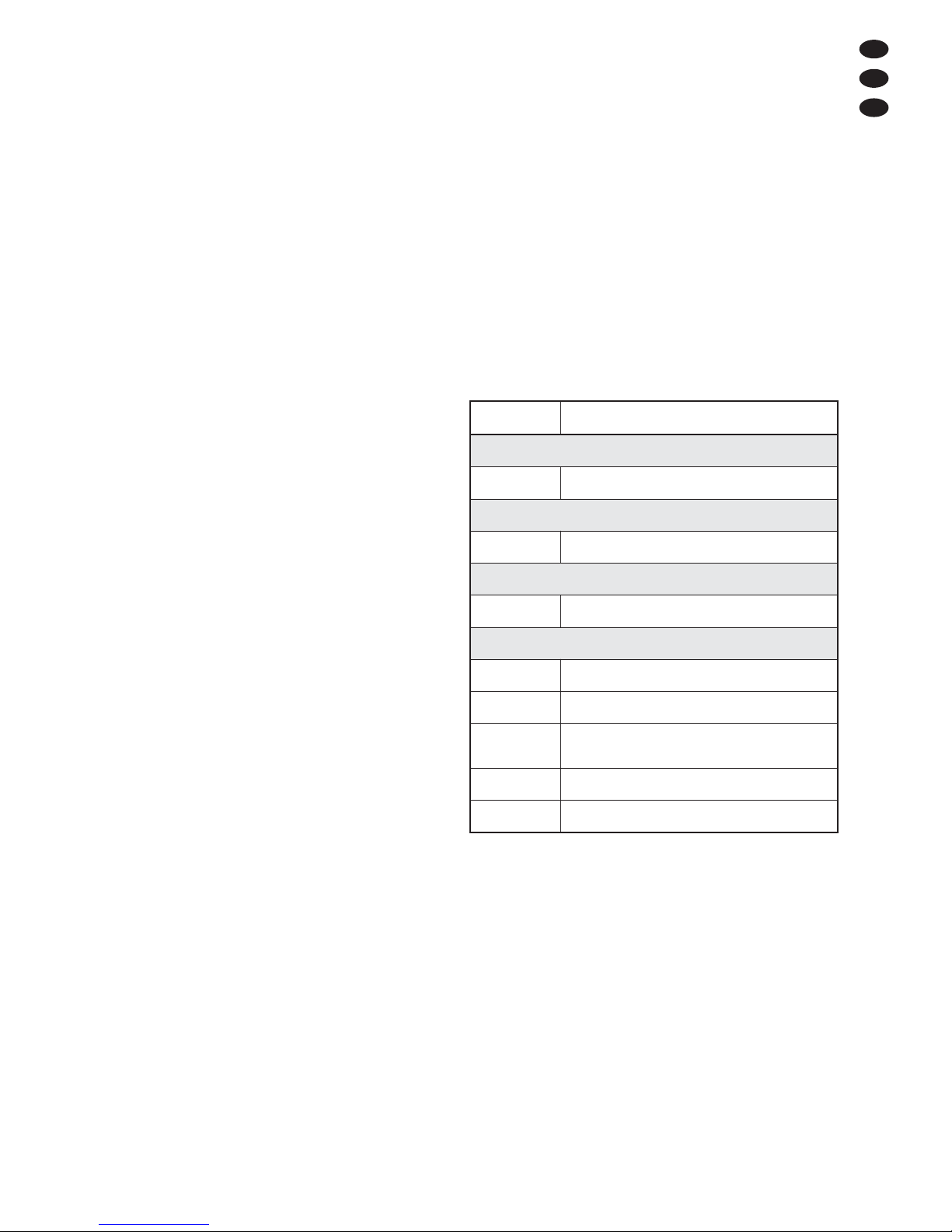
7.2 Adjusting the start address
For operation of the spotlight with a light controller,
adjust the DMX start address for the first DMX chan-
nel. If e. g. address 17 on the controller is provided for
controlling the colour red, adjust the start address 17
on the spotlight. The other functions of the spotlight
(green, blue, dimmer) will then automatically be as-
signed to the three following channels (in this example
18 to 20). As the next possible start address for the fol-
lowing DMX-controlled unit, address 21 could be used
in this example.
There are two methods for adjusting the address:
7.2.1 Automatic address adjustment
This method makes sense when several PARL-
30SPOT or PARL-30WASH units are used for which
addresses of low range are desired:
1) Disconnect the input DMX input (4) of the first spot-
light from the controller or switch off the controller
so that there is no DMX signal at the input of the
spotlight.
2) Press the button DMX ADDRESS SETTING (5) on
the first spotlight for five seconds. The spotlight and
the spotlights connected to it will then be dark.
3) Reconnect the controller or switch on the controller
again.
The start address of the first spotlight is now set to 1;
the start addresses of the following spotlights to 5, 9,
13, etc.
7.2.2 Address adjustment via the controller
With this method, any start address desired can easily
be assigned to a spotlight:
1) At the controller, set the DMX value of the channel
corresponding to the start address to be adjusted to
the maximum (255). Set the values of all other DMX
channels to zero. For adjusting, e. g. start address
17, fully advance channel 17 on the controller and
set all other channels to zero.
10
GB

2) On all spotlights to which this start address is to be
assigned, shortly press the button DMX ADDRESS
SETTING (5).
Repeat these operating steps until an address has
been assigned to each spotlight.
7.3 Control with LED-4C
The unit LED-4C by “img Stage Line” is an easy-to-use
controller specially designed for these LED spotlights.
It is equipped with 4 channels so that all spotlights con-
nected to it can only be controlled in sync.
Set the start address of the spotlights to 1 or to a
multiple of 4 + 1 (5, 9, 13, … 61 max.), chapter
7.2.1. Detailed information for operation can be found
in the manual of LED-4C.
8 Cleaning the Spotlight
The plastic pane of the spotlight cover (10) should be
cleaned at regular intervals from the outside, and if
necessary, also from the inside, depending on impuri-
ties caused by dust, smoke, or other dirt particles. Only
this will ensure that the light is emitted at maximum
brightness.
1) For cleaning use a soft, clean cloth and a mild
detergent. Then wipe the plastic plane dry.
2) For cleaning the pane from the inside, remove the
spotlight cover (10).
CAUTION! Always disconnect the mains plug from
the socket before opening the spotlight.
a) Release the locking screw (11) and slide the
latch (12) to the rear.
b) Slightly turn the spotlight cover counter-clock-
wise so that it will unlock and can be removed.
c) Clean the pane from the inside and reassemble
the spotlight in reverse order.
9 Specifications
Power supply: . . . . . . . . 230 V~/50 Hz
Power consumption: . . . 10 VA
Illuminant
PARL-30SPOT: . . . . 90 extra bright 5 mm LEDs
red: 24, green: 33, blue: 33,
beam angle: 20°
PARL-30WASH: . . . . 91 extra bright 5 mm LEDs
red: 31, green: 30, blue: 30,
beam angle: 120°
Ambient temperature: . . 0 – 40 °C
Dimensions. . . . . . . . . . Ø 120 mm × 120 mm
Weight: . . . . . . . . . . . . . 1kg
Cable length: . . . . . . . . 1.2m
9.1 DMX channels
Subject to technical modification.
DMX value Function
Channel 1: proportion of red
0 – 255 brightness of red LEDs
Channel 2: proportion of green
0 – 255 brightness of green LEDs
Channel 3: proportion of blue
0 – 255 brightness of blue LEDs
Channel 4: dimmer/stroboscope/music
0–7 LEDs off
8 – 190 dimmer
191 – 200 music-controlled change of colour
via integrated microphone
201 – 247 stroboscopic effect: slow →fast
248 – 255 full brightness
11
GB
All rights reserved by MONACOR
®
INTERNATIONAL GmbH & Co. KG. No part of this instruction manual may
be reproduced in any form or by any means for any commercial use.

Ouvrez le présent livret page 3 de manière à visua-
liser les éléments et branchements.
1 Eléments et branchements
1.1 Face arrière
1Vis de blocage pour lʼétrier de montage (9)
2Prise de branchement pour la télécommande LC-3
3Sortie signal DMX (XLR 3 pôles) pour brancher à
lʼentrée DMX dʼun autre jeu de lumière DMX :
1 = masse, 2 = DMX
-
, 3 = DMX+
4Entrée signal DMX (XLR, 3 pôles) :
1 = masse, 2 = DMX
-
, 3 = DMX+
5Touche pour le réglage des adresses DMX
(voir chapitre 7.2)
6Cordon secteur à relier à une prise secteur
230 V~/50 Hz
7Plaque de montage pour fixer le projecteur sur un
mur ou au plafond
8Vis pour la plaque de montage
9Etrier de montage
10 Couvercle du boîtier avec vitre en plastique
11 Vis de réglage pour le verrouillage (12)
12 Verrouillage pour le couvercle du boîtier
1.2 Télécommande LC-3
La télécommande est disponible en option mais nʼest
pas livrée avec le projecteur à LEDs.
13 Touche STAND BY pour la fonction Blackout
(lumière éteinte)
14 Touche FUNCTION pour sélectionner différentes
fonctions de changement de lumière selon le mode
de fonctionnement sélectionné avec la touche
MODE
15 Touche MODE pour commuter entre
Mode Sound 1 (la LED ne brille pas)
Mode Manuel (la LED brille)
Mode Sound 2 (la LED clignote lentement)
Mode Auto (la LED clignote vite)
Conseil : Pour une gestion via la télécommande,
aucun signal DMX ne doit pas être présent à lʼentrée
DMX IN (4).
2 Conseils dʼutilisation et de sécurité
Le projecteur répond à toutes les directives nécessaires
de lʼUnion européenne et porte donc le symbole .
Respectez scrupuleusement les points suivants :
Le projecteur nʼest conçu que pour une utilisation en
intérieur. Protégez-le de tout type de projections
dʼeau, des éclaboussures, dʼune humidité élevée
dʼair et de la chaleur (plage de température de
fonctionnement autorisée : 0 – 40 °C).
Ne faites pas fonctionner le projecteur ou débran-
chez-le immédiatement du secteur lorsque :
1. des dommages visibles apparaissent sur lʼappa-
reil ou sur le cordon secteur,
2. après une chute ou un cas similaire, vous avez un
doute sur lʼétat de lʼappareil,
3. des dysfonctionnements apparaissent.
Dans tous les cas, les dommages doivent être répa-
rés par un technicien spécialisé.
Tout cordon secteur endommagé ne doit être rem-
placé que par un technicien habilité.
Ne débranchez jamais lʼappareil en tirant sur le cor-
don secteur ; retirez toujours le cordon secteur en
tirant la fiche.
Pour le nettoyage, utilisez seulement un chiffon sec
et doux, en aucun cas, de produits chimiques ou
dʼeau.
Nous déclinons toute responsabilité en cas de dom-
mages matériels ou corporels résultants si le pro-
jecteur est utilisé dans un but autre que celui pour
lequel il a été conçu, sʼil nʼest pas monté de manière
sûre, nʼest pas correctement utilisé ou nʼest pas
réparé par une personne habilitée, en outre, la
garantie deviendrait caduque.
3 Possibilités dʼutilisation
Le projecteur est conçu pour une utilisation sur scène,
en discothèque et dans des salles des fêtes ou pour
décorer. Il crée une lumière de couleur via des LEDs
5 mm extrêmement claires, brillant en bleu, rouge et
vert :
PARL-30SPOT : 90 LEDs, angle de diffusion 20°
PARL-30WASH : 91 LEDs, angle de diffusion 120°
Ainsi, des changements de couleur gérés par la musi-
que, des transitions lentes de couleurs et des effets
stroboscopiques sont possibles.
Lorsque le projecteur est définitivement retiré
du service, vous devez le déposer dans une
usine de recyclage adaptée pour contribuer à
son élimination non polluante.
AVERTISSEMENT Le projecteur est alimenté par
une tension dangereuse 230 V~.
Ne touchez jamais lʼintérieur de
lʼappareil et ne faites rien tomber
dans les ouïes de ventilation !
Risque de décharge électrique.
12
F
B
CH

Le projecteur est configuré pour être géré via un
contrôleur DMX (4 canaux de commande DMX) ; il
peut également fonctionner sans contrôleur ou avec la
télécommande LC-3, disponible en option.
4 Montage
Placez toujours lʼappareil de telle sorte quʼune cir-
culation dʼair suffisante soit assurée pendant le
fonctionnement. En aucun cas les ouïes de ventila-
tion sur le boîtier ne doivent être obturées (par
exemple par des rideaux).
La distance minimale avec lʼobjet à éclairer doit être
de 10 cm.
1) Vissez lʼétrier de montage (9) sur le boîtier du pro-
jecteur avec les deux vis papillon (1).
2) Fixez le projecteur via lʼétrier de montage (9), sur
une traverse avec par exemple une vis de montage
solide ou un support pour projecteur (crochet C).
Si le projecteur doit être fixé sur un mur ou au
plafond, vissez la plaque de montage (7) sur lʼétrier
selon le schéma 1. Fixez la plaque de montage
avec le projecteur à lʼendroit voulu sur le mur ou le
plafond.
3) Pour orienter le projecteur, desserrez les deux vis
de blocage (1) sur lʼétrier de montage. Réglez lʼin-
clinaison voulue puis revissez les vis.
Si le projecteur est vissé sur la plaque de mon-
tage (7), desserrez un peu la vis (8), si nécessaire,
tournez lʼétrier de montage (9) comme souhaité
puis revissez la vis.
5 Mise en service
Pour allumer le projecteur, mettez la fiche du cordon
secteur (6) dans une prise secteur 230 V~/50 Hz. Pour
lʼéteindre, débranchez le cordon secteur.
Pour un meilleur confort dʼutilisation, il est recom-
mandé de relier le projecteur à une prise secteur pou-
vant être allumée et éteinte via un interrupteur.
Attention ! Le projecteur ne doit pas être relié à lʼali-
mentation via un dimmer.
6 Fonctionnement sans contrôleur
Si le récepteur ne reçoit aucun signal de commande
DMX, il change tout seul la couleur avec des transi-
tions lentes.
Si la musique va à un rythme marqué dans la plage
des graves, à un volume suffisant, le projecteur
change la couleur au rythme de la musique, géré par
un microphone interne. Si la gestion par la musique ne
fonctionne pas de manière optimale, augmentez le
volume ou diminuez la distance entre la source sonore
et le projecteur.
6.1 Fonctionnement combiné de plusieurs
projecteurs
Il est possible de faire fonctionner ensemble plusieurs
PARL-30SPOT et PARL-30WASH (même combinés)
pour changer les couleurs de manière synchrone ou
pour contrôler les appareils auxiliaires au même
rythme via le microphone interne de lʼappareil princi-
pal.
Reliez la connexion DMX OUT (3) de lʼappareil prin-
cipal via un cordon XLR 3 pôles (p. ex. MEC-… ou
MECN-… de la gamme “img Stage Line”) à lʼentrée
DMX IN (4) du premier appareil auxiliaire.
Reliez la connexion DMX OUT du premier appareil
auxiliaire à la connexion DMX IN du deuxième appareil
auxiliaire et ainsi de suite.
6.2 Télécommande LC-3
Via la télécommande LC-3 disponible en option, diver-
ses fonctions peuvent être gérées en plus de la ges-
tion par la musique.
1) Reliez la télécommande à la prise REMOTE CON-
TROL (2).
2) Aucun signal DMX ne doit être présent à lʼentrée
DMX IN (4).
3) Via la sortie DMX OUT (3), on peut brancher dʼau-
tres PARL-30SPOT ou PARL-30WASH (voir chapi-
tre 6.1) pour les gérer de manière synchrone à lʼap-
pareil principal avec la télécommande.
4) Avec la touche STAND BY (13), la fonction Blackout
peut être activée ou éteinte. Si la fonction est acti-
vée, la lumière est coupée et la LED à côté de la
touche brille.
5) Avec la touche MODE (15), sélectionnez le mode
de fonctionnement :
a) Après lʼallumage du projecteur, le mode
SOUND 1 est activé. La LED à côté de la touche
MODE ne brille pas. Si la touche FUNCTION
AVERTISSEMENT Ne regardez jamais directement
les LEDs, cela pourrait générer
des troubles de la vision.
Faites attention : des change-
ments très rapides de lumière
peuvent déclencher chez les per-
sonnes photosensibles et les épi-
leptiques des crises dʼépilepsie !
AVERTISSEMENT Le projecteur doit être monté
de manière professionnelle et
sûre. Si lʼappareil doit être
installé au-dessus de person-
nes, il doit être en plus assuré
(par exemple avec une corde
de sécurité sur lʼétrier de
montage. Fixez la corde de
telle sorte que la distance de
chute de lʼappareil ne puisse
pas être supérieure à 20 cm).
13
F
B
CH

(14) est maintenue enfoncée, un effet strobo-
scopique dépendant de la musique est créé. A
chaque nouvelle pression sur la touche, il passe
de lumière blanche, lumière de couleur chan-
geante (pour plusieurs projecteurs comme courte
séquence avec uniquement un éclair par pro-
jecteur ; la couleur est identique sur tous les pro-
jecteurs) à lumière de couleur changeante avec
différentes couleurs sur plusieurs projecteurs.
b) Pour commuter sur le mode MANUAL, appuyez
une fois sur la touche MODE. La LED à côté de
la touche brille. Avec la touche FUNCTION, on
peut sélectionner une des couleurs suivantes :
blanc, rouge, bleu, violet, orange, vert, jaune,
magenta, cyan.
c) Pour commuter sur le mode SOUND 2, appuyez
une nouvelle fois sur la touche MODE. La LED à
côté de la touche clignote lentement. Avec la
touche FUNCTION, on peut sélectionner entre
cinq options de changement de couleurs et
séquences gérées par la musique, par des pres-
sions répétées. Ces options nʼont dʼintérêt que si
plusieurs projecteurs sont branchés ensemble.
d) Pour commuter sur le mode AUTO, appuyez
une nouvelle fois sur la touche MODE. La LED à
côté de la touche clignote rapidement. Avec ce
mode de fonctionnement, les couleurs changent
automatiquement par transition. La musique en
cours nʼa pas dʼinfluence. Avec la touche
FUNCTION, on peut sélectionner entre trois
vitesses de transition par des pressions répé-
tées.
Pour revenir au mode SOUND 1, appuyez une
nouvelle fois sur la touche MODE.
7 Utilisation via un contrôleur
Pour une utilisation via un contrôleur avec protocole
DMX512 (par exemple DMX-1440 ou DMX-510USB
de “img Stage Line”), le projecteur dispose de quatre
canaux de commande. Les fonctions des canaux et les
valeurs DMX sont décrites dans le chapitre 9.1.
7.1 Branchement
Le projecteur possède comme interface DMX des pri-
ses XLR 3 pôles avec la configuration suivante :
1 = masse, 2 = DMX
-
, 3 = DMX +.
Pour le branchement, il est recommandé dʼutiliser des
câbles spécifiques pour des flots importants de don-
nées. Lʼemploi de câbles micro blindés usuels avec
une section de 2 × 0,22 mm2au moins et la capacité la
plus faible possible nʼest recommandé que pour des
longueurs de câble de 100 m maximum. Pour des
longueurs de liaison à partir de 150 m, il est recom-
mandé dʼinsérer un amplificateur DMX de signal (par
exemple SR-103DMX de “img Stage Line”).
1) Reliez lʼentrée DMX (4) à la sortie DMX du jeu de
lumière.
2) Reliez la sortie DMX (3) à lʼentrée DMX du jeu de
lumière suivant. Reliez sa sortie à lʼentrée du pro-
chain appareil et ainsi de suite jusquʼà ce que tous
les jeux de lumière soient reliés dans une chaîne.
3) Terminez la sortie DMX du dernier appareil DMX de
la chaîne avec une résistance 120 Ω (> 0,3 W) :
soudez aux pins 2 et 3 dʼune fiche XLR la résis-
tance et branchez la fiche dans la sortie DMX ou uti-
lisez un bouchon correspondant (p. ex. DLT-123 de
“img Stage Line”).
7.2 Réglage de lʼadresse de démarrage
Pour pouvoir utiliser le projecteur avec un contrôleur, il
faut régler lʼadresse de démarrage DMX pour le pre-
mier canal DMX. Si par exemple sur le contrôleur,
lʼadresse 17 est prévue pour le contrôle de la couleur
Rouge, réglez sur le projecteur lʼadresse de démar-
rage 17. Les autres fonctions du projecteur (vert, bleu,
dimmer), sont automatiquement attribuées aux trois
canaux suivants (dans cet exemple 18 à 20). Comme
adresse de démarrage pour lʼappareil suivant à ges-
tion DMX immédiatement suivante on peut utiliser,
dans cet exemple, lʼadresse 21.
Pour régler lʼadresse, deux méthodes existent :
7.2.1 Réglage automatique des adresses
Cette méthode est utile si plusieurs PARL-30SPOT ou
PARL-30WASH doivent être utilisés et dont les adres-
ses sont dans la plage inférieure :
1) Séparez lʼentrée DMX (4) du premier projecteur du
contrôleur ou éteignez le contrôleur de telle sorte
quʼaucun signal DMX ne soit présent à lʼentrée du
projecteur.
2) Appuyez pendant cinq secondes sur la touche DMX
ADDRESS SETTING (5) sur le premier projecteur.
Le projecteur et ceux reliés sont alors sombres.
3) Rétablissez la liaison avec le contrôleur ou rallumez
le contrôleur.
Lʼadresse de démarrage du premier projecteur est
réglée sur 1, les adresses de démarrage des appareils
suivants sur 5, 9, 13 etc.
7.2.2 Réglage des adresses via le contrôleur
Avec cette méthode, on peut attribuer à un projecteur
une adresse quelconque de démarrage de manière
simple :
1) Sur le contrôleur, réglez la valeur DMX du canal qui
correspond à lʼadresse de démarrage à régler, sur
le maximum (255). Mettez les valeurs de tous les
autres canaux DMX sur zéro. Si par exemple
lʼadresse de démarrage 17 doit être réglée, ouvrez
complètement le canal 17 sur le contrôleur et met-
tez sur zéro tous les autres canaux.
2) Pour tous les projecteurs devant recevoir cette
adresse de démarrage, appuyez brièvement sur la
touche DMX ADDRESS SETTING (5).
Répétez ces points jusquʼà ce que chaque projecteur
aie son adresse.
14
F
B
CH

7.3 Gestion avec le LED-4C
Le LED-4C de “img Stage Line” est un contrôleur
simple dʼutilisation spécialement conçu pour ces pro-
jecteurs à LEDs. Il dispose de 4 canaux, tous les pro-
jecteurs reliés ne peuvent être gérés que de manière
synchrone.
Réglez lʼadresse de démarrage pour les pro-
jecteurs sur 1 ou sur un multiple de 4 + 1 (5, 9, 13, …
61 max.), voir chapitre 7.2.1. Reportez-vous à la notice
du LED-4C pour plus de détails.
8 Nettoyage du projecteur
La vitre plastique du couvercle du projecteur (10) doit
être nettoyée à intervalles réguliers de toute pous-
sière, fumée ou autres particules salissantes, de lʼinté-
rieur et de lʼextérieur. Cʼest à cette seule condition que
la lumière sera diffusée avec une luminosité maximale.
1) Pour le nettoyage, utilisez un chiffon doux, propre
et un produit nettoyant doux. Ensuite essuyez la
vitre de plastique.
2) Pour pouvoir nettoyer la vitre de lʼintérieur, il faut
retirer le couvercle du projecteur (10).
ATTENTION ! Avant dʼouvrir le projecteur, débran-
chez impérativement la fiche secteur de la prise
secteur.
a) Desserrez la vis de blocage (11), poussez le ver-
rouillage (12) vers lʼarrière.
b) Tournez le couvercle du projecteur un peu dans
le sens inverse des aiguilles dʼune montre pour
quʼil se désenclenche et puisse être retiré.
c) Nettoyez la vitre de lʼintérieur, puis remontez le
projecteur dans lʼordre inverse.
9 Caractéristiques techniques
Alimentation : . . . . . . . . 230 V~/50 Hz
Consommation : . . . . . . 10 VA
Lampes
PARL-30SPOT : . . . . 90 LEDs 5 mm extrême-
ment claires, 24 rouges,
33 vertes, 33 bleues,
angle de diffusion 20°
PARL-30WASH : . . . 91 LEDs 5 mm extrême-
ment claires, 31 rouges,
30 vertes, 30 bleues,
angle de diffusion 120°
Température de fonc. : . 0 – 40 °C
Dimensions : . . . . . . . . Ø 120 mm × 120 mm
Poids : . . . . . . . . . . . . . 1 kg
Longueur de câble : . . . 1,2 m
9.1 Canaux DMX
Tout droit de modification réservé.
Valeur DMX Fonction
Canal 1: Part de rouge
0 – 255 luminosité du rouge
Canal 2: Part de vert
0 – 255 luminosité du vert
Canal 3: Part de bleu
0 – 255 luminosité du bleu
Canal 4: Dimmer/Stroboscope/Musique
0–7 LEDs éteintes
8 – 190 dimmer
191 – 200 changement de couleur géré par
la musique via le microphone intégré
201 – 247 effet stroboscope: lent →rapide
248 – 255 luminosité maximale
15
F
B
CH
Notice dʼutilisation protégée par le copyright de MONACOR
®
INTERNATIONAL GmbH & Co. KG. Toute repro-
duction même partielle à des fins commerciales est interdite.

Vi preghiamo di aprire completamente la pagina 3.
Così vedrete sempre gli elementi di comando e i
collegamenti descritti.
1 Elementi di comando e collegamenti
1.1 Faretto
1Viti di bloccaggio per la staffa di montaggio (9)
2Presa di collegamento per il telecomando LC-3
3Uscita segnale DMX (XLR a 3 poli) per il collega-
mento con lʼingresso DMX di unʼulteriore unità per
effetti luce;
1 = massa, 2 = DMX
-
, 3 = DMX+
4Ingresso segnale DMX (XLR a 3 poli);
1 = massa, 2 = DMX
-
, 3 = DMX+
5Tasto per lʼimpostazione dellʼinidirizzo DMX,
(vedi Capitolo 7.2)
6Cavo rete per il collegamento con una presa
(230 V~/50 Hz)
7Piastra di montaggio per il fissaggio alla parete o al
soffitto
8Vite per la piastra di montaggio
9Staffa di montaggio
10 Coperchio con disco di plastica
11 Vite di fissaggio per il bloccaggio (12)
12 Bloccaggio del coperchio
1.2 Telecomando LC-3
Il telecomando è disponibile come accessorio e non è
in dotazione con il faretto a LED.
13 Tasto STAND BY per la funzione Blackout (luce
spenta)
14 Tasto FUNCTION per scegliere diverse funzioni di
cambio luce a seconda del modo di funzionamento
determinato con il tasto MODE
15 Tasto MODE per cambiare fra
Modo Sound 1 (LED spento)
Modo manuale (LED acceso)
Modo Sound 2 (LED lampeggia lentamente)
Modo auto (LED lampeggia velocemente)
N.B.: Per usare il telecomando, allʼingresso DMX IN
(4) non deve essere presente nessun segnale DMX.
2 Avvertenze di sicurezza
Il faretto è conforme a tutte le direttive richieste dellʼUE
e pertanto porta la sigla .
Si devono osservare assolutamente anche i seguenti
punti:
Usare il faretto solo allʼinterno di locali e proteggerlo
dallʼacqua gocciolante e dagli spruzzi dʼacqua, da
alta umidità dellʼaria e dal calore (temperatura dʼim-
piego ammessa fra 0 e 40 °C).
Non mettere in funzione il faretto e staccare subito la
spina rete se:
1. lʼapparecchio o il cavo rete presentano dei danni
visibili;
2. dopo una caduta o dopo eventi simili sussiste il
sospetto di un difetto;
3. lʼapparecchio non funziona correttamente.
Per la riparazione rivolgersi sempre ad unʼofficina
competente.
Il cavo rete, se danneggiato, deve essere sostituito
solo da un laboratorio specializzato
Staccare il cavo rete afferrando la spina, senza tirare
il cavo.
Per la pulizia usare solo un panno morbido, asciutto;
non impiegare in nessun caso prodotti chimici o
acqua.
Nel caso dʼuso improprio, di montaggio non sicuro,
dʼimpiego scorretto o di riparazione non a regola
dʼarte del faretto, non si assume nessuna responsabi-
lità per eventuali danni consequenziali a persone o a
cose e non si assume nessuna garanzia per il faretto.
3 Possibilità dʼimpiego
Il faretto è indicato per lʼimpiego sul palcoscenico, in
discoteche o per party oppure per decorazione. Pro-
duce una luce colorata per mezzo dei LED superlumi-
nosi di 5 mm nei colori blu, rosso e verde:
PARL-30SPOT: 90 LED, angolo dʼirradiazione 20°
PARL-30WASH: 91 LED, angolo dʼirradiazione 120°
Sono possibili dei cambi di colori comandati dalla
musica, delle dissolvenze lente fra i colori nonché degli
effetti stroboscopici.
Il faretto è previsto per il comando attraverso
unʼunità di comando luce DMX (4 canali di controllo
DMX), ma può essere usato anche senza unità di
comando oppure tramite il telecomando LC-3 disponi-
bile come accessorio.
Se si desidera eliminare il faretto definitiva-
mente, consegnarlo per lo smaltimento ad
unʼistituzione locale per il riciclaggio.
AVVERTIMENTO Lʼapparecchio funziona con peri-
colosa tensione di rete (230 V~).
Non intervenire mai al suo
interno e non inserire niente nelle
fessure di aerazione! Esiste il
pericolo di una scarica elettrica.
16
I

4 Montaggio
Posizionare lʼapparecchio in modo tale che durante
il funzionamento sia garantita una circolazione suf-
ficiente dellʼaria. Le aperture dʼaerazione sul conte-
nitore non devono essere coperte in nessun caso
(p. es. da tende).
La distanza da un oggetto irradiato deve essere non
inferiore a 10 cm.
1) Avvitare la staffa di montaggio (9) sul contenitore
del faretto per mezzo delle due viti ad alette (1).
2) Fissare il faretto per mezzo della sua staffa di mon-
taggio (9), p. es. con una robusta vite di montaggio
oppure con un supporto per fari (gancio a C) ad una
traversa.
Se il faretto deve essere fissato al soffitto o alla
parete, avvitare la piastra di montaggio (7) alla
staffa come da figura 1. Avvitare la piastra con il
faretto in un posto adatto del soffitto o della parete.
3) Per orientare il faretto allentare le due viti di bloc-
caggio (1) sulla staffa di montaggio. Impostare lʼin-
clinazione desiderata del faretto e stringere nuova-
mente le viti.
Se il faretto è avvitato alla piastra di montaggio
(7), allentare eventualmente la vite (8), girare la
staffa di montaggio (9) come desiderato e stringere
di nuovo la vite
5 Messa in funzione
Per accendere il faretto inserire la spina del cavo rete
(6) in una presa (230 V~/50 Hz), per lo spegnimento
staccare la spina.
Per maggiore comodità è consigliabile collegare il
faretto con una presa comandata da un interruttore di
luce.
Attenzione: Il faretto non deve essere collegato con la
tensione di rete per mezzo di un dimmer!
6 Funzionamento senza
unità di comando
Se il faretto non riceve nessun segnale DMX di
comando, cambia automaticamente i colori con dissol-
venze lente.
Se cʼè della musica con chiaro ritmo nei bassi, il
faretto, comandato da un microfono integrato, cambia
il colore nel ritmo della musica. Se il comando musica
non dovesse funzionare in modo ottimale, aumentare
il volume oppure ridurre la distanza fra sorgente
sonora e faretto.
6.1 Assemblaggio di più faretti
Si possono unire più PARL-30SPOT e PARL-30WASH
(anche misti), per ottenere un cambio sincronizzato dei
colori oppure per comandare, tramite il microfono
interno dellʼapparecchio principale, tutti gli apparecchi
secondari nello stesso ritmo.
Per fare ciò collegare il contatto DMX OUT (3)
dellʼapparecchio principale con il contatto DMX IN (4)
del primo apparecchio secondario servendosi di una
cavo XLR a 3 poli (p. es. serie MEC-... o MECN-... del
programma di “img Stage Line”).
Collegare il contatto DMX OUT del primo appa-
recchio secondario con il contatto DMX IN del secondo
apparecchio secondario ecc.
6.2 Telecomando tramite LC-3
Per mezzo del telecomando LC-3 disponibile come
accessorio è possibile comandare diverse funzioni
oltre al comando tramite la musica.
1) Collegare il telecomando con la presa REMOTE
CONTROL (2).
2) Allʼingresso DMX IN (4) non deve essere presente
nessun segnale DMX.
3) Attraverso lʼuscita DMX OUT (3) è possibile colle-
gare ulteriori PARL-30SPOT o PARL-30WASH
(Capitolo 6.1), per comandarli insieme con lʼap-
parecchio principale per mezzo del telecomando.
4) Con il tasto STAND BY (13) si può attivare e disat-
tivare la funzione Blackout. Con la funzione attivata,
la luce viene mascherata e il LED vicino al tasto si
accende.
5) Con il tasto MODE (15) selezionare il modo di fun-
zionamento:
a) Dopo lʼaccensione del faretto è attivato il modo
SOUND 1. Il LED vicino al tasto MODE è spento.
Se si tiene premuto il tasto FUNCTION (14), si
produce un effetto stroboscopico dipendente
dalla musica. Con ogni nuova pressione del
tasto, lʼeffetto cambia fra luce bianca, luce di vari
colori (nel caso di più faretti come sequenza
breve con un solo lampo per faretto; il colore è lo
stesso in tutti i faretti) e luce di vari colori con
colori differenti nel caso di più faretti.
b) Per passare al modo MANUAL premere una
volta il tasto MODE. Il LED vicino al tasto si
AVVERTIMENTO Non guardare direttamente nei
LED per escludere possibili danni
agli occhi.
Tenete presente che i veloci
cambi di luce possono provocare
attacchi dʼepilessia presso per-
sone fotosensibili o epilettici!
AVVERTIMENTO Il faretto deve essere montato
a regola dʼarte e in modo
sicuro. Se viene installato in
modo sospeso sopra delle
persone è richiesto un siste-
ma di sicurezza supplemen-
tare (p. es. per mezzo di una
fune di trattenuta fissata alla
staffa di montaggio; fissare la
fune in modo tale che la
caduta dellʼunità non possa
superare i 20 cm).
17
I

accende. Con il tasto FUNCTION si può ora sce-
gliere uno dei seguenti colori:
bianco, rosso, blu, viola, arancio, verde, giallo,
magenta, cyan
c) Per passare al modo SOUND 2 premere unʼaltra
volta il tasto MODE. Il LED vicino al tasto lam-
peggia lentamente. Con il tasto FUNCTION si
possono scegliere, premendo ripetutamente,
cinque differenti opzioni e sequenze di cambio
colori comandato dalla musica. Queste opzioni
hanno senso solo alla presenza di più faretti col-
legati fra loro.
d) Per passare al modo AUTO premere unʼaltra
volta il tasto MODE. Il LED vicino al tasto lam-
peggia velocemente. In questo modo i colori
cambiano automaticamente con dissolvenze. La
musica non influisce sul cambio. Con il tasto
FUNCTION si possono scegliere, premendo
ripetutamente, tre differenti velocità per le dis-
solvenze.
Per ritornare nel modo SOUND 1 premere
ancora il tasto MODE.
7 Funzionamento attraverso unʼunità
di comando luce
Per il funzionamento attraverso unʼunità di comando
luce con protocollo DMX512 (p. es. DMX-1440 o DMX-
510USB di “img Stage Line”), il faretto dispone di quat-
tro canali di comando. Le funzioni dei canali e i valori
DMX si trovano nel capitolo 9.1.
7.1 Collegamento
Come interfaccia DMX, il faretto possiede delle prese
XLR a 3 poli con i seguenti contatti:
1 = massa, 2 = DMX
-
, 3 = DMX+
Per il collegamento si dovrebbero usare cavi per un
forte flusso di dati. Lʼimpiego di normali cavi schermati
per microfoni con sezione minima di 2 × 0,22 mm2e
con capacità possibilmente ridotta è consigliabile solo
nel caso di una lunghezza complessiva inferiore a
100 m. Nel caso di lunghezze oltre i 150 m si consiglia
lʼimpiego di un amplificatore DMX (p. es. SR-103DMX
di “img Stage Line”).
1) Collegare lʼingresso DMX (4) con lʼuscita DMX
dellʼunità di comando.
2) Collegare lʼuscita DMX (3) con lʼingresso DMX della
successiva unità per effetti luce. Quindi collegare
lʼuscita di questʼultima con lʼingresso dellʼappa-
recchio a valle ecc. fino al collegamento di tutte le
unità in una catena.
3) Terminare lʼuscita DMX dellʼultima unità DMX della
catena con un resistenza 120 Ω (> 0,3 W): saldare
la resistenza ai pin 2 e 3 di un connettore XLR ed
inserire il connettore nellʼuscita DMX, oppure usare
un relativo connettore terminatore (p. es. DLT-123
di “img Stage Line”).
7.2 Impostare lʼindirizzo di start
Per poter usare il faretto con unʼunità di comando luce,
occorre impostare lʼindirizzo di start DMX per il primo
canale DMX. Se, per esempio, sullʼunità di comando è
previsto lʼindirizzo 17 per il comando del colore rosso,
si deve impostare sul faretto lʼindirizzo di start 17. Le
altre funzioni del faretto (verde, blu, dimmer) saranno
assegnati automaticamente ai tre canali successivi (nel
nostro esempio 18 – 20). Un altro possibile indirizzo di
start per lʼapparecchio successivo comandato da DMX,
potrebbe essere nel nostro esempio lʼindirizzo 21.
Per impostare lʼindirizzo sono disponibili i seguenti due
metodi:
7.2.1 Impostazione automatica dellʼindirizzo
Questo metodo ha senso se si impiegano più PARL-
30SPOT o PARL-30WSH e se i loro indirizzi devono
essere bassi:
1) Staccare dallʼunità di comando lʼingresso DMX (4)
del primo faretto oppure spegnere lʼunità di
comando in modo che allʼingresso del faretto non
sia presente nessun segnale DMX.
2) Premere per cinque secondi il tasto DMX
ADDRESS SETTING (5) sul primo faretto. Il faretto
e i faretti collegati con lo stesso diventano bui.
3) Ripristinare il collegamento con lʼunità di comando
oppure riaccendere detta unità.
Lʼindirizzo di start del primo faretto è ora messo su 1,
gli indirizzi di start dei faretti seguenti sono 5, 9, 13 ecc.
7.2.2 Impostazione dellʼindirizzo attraverso lʼunità
di comando
Con questo metodo è semplice assegnare ad un
faretto un qualsiasi indirizzo di start:
1) Sullʼunità di comando mettere il valore DMX del
canale che corrisponde allʼindirizzo da impostare
sul massimo (255). Mettere sullo zero i valori di tutti
gli altri canali DMX. Se si deve impostare per esem-
pio lʼindirizzo di start 17, aprire completamente il
canale 17 sullʼunità di comando e mettere tutti gli
altri canali sullo zero.
2) Per tutti i faretti che devono avere questo indirizzo
di start premere brevemente il tasto DMX
ADDRESS SETTING (5).
Ripetere questi passi finché ogni faretto ha avuto il suo
indirizzo.
7.3 Comando tramite il LED-4C
Lʼapparecchio LED-4C di “img Stage Line” è unʼunità
di comando facile da usare, specialmente per questi
faretti a LED. Dispone di 4 canali così che tutti i faretti
collegati possono essere comandati in modo sincro-
nizzato.
Impostare lʼindirizzo di start dei faretti su 1 o su un
multiplo di 4 + 1 (5, 9, 13, … max. 61), Capi-
tolo 7.2.1. Delle indicazioni più particolari sul funziona-
mento si trovano nelle istruzioni del LED-4C.
18
I

8 Pulizia del faretto
Il disco di plastica del coperchio del faretto (10) do-
vrebbe essere pulito ad intervalli regolari, a secondo
della presenza di sporco per polvere, fumo o altre par-
ticelle. La pulizia dovrebbe riguardare il lato esterno ed
eventualmente anche quello interno. Solo in questo
modo è garantito che la luce venga irradiata con la
massima luminosità..
1) Per la pulizia usare un panno morbido, pulito,
insieme ad un detergente delicato. Quindi asciu-
gare il disco di plastica.
2) Per poter pulire lʼinterno del disco occorre staccare
il coperchio (10).
ATTENZIONE! Prima di aprire il coperchio staccare
assolutamente la spina dalla presa di rete.
a) Allentare la vite di fissaggio (11) e spostare allʼin-
dietro il blocco (12).
b) Girare il coperchio un poʼ in senso antiorario in
modo che si sganci per poter essere tolto.
c) Pulire il disco dallʼinterno e riassemblare il
faretto in ordine inverso.
9 Dati tecnici
Alimentazione: . . . . . . . 230 V~/50 Hz
Potenza assorbita: . . . . 10 VA
Lampadine
PARL-30SPOT: . . . . 90 LED superluminosi
di 5 mm
24 rosso, 33 verde, 33 blu,
Angolo dʼirradiazione 20°
PARL-30WASH: . . . . 91 LED superluminosi
di 5 mm
31 rosso, 30 verde, 30 blu,
Angolo dʼirradiazione 120°
Temperatura dʼesercizio: 0 – 40 °C
Dimensioni: . . . . . . . . . Ø 120 mm × 120 mm
Peso: . . . . . . . . . . . . . . 1 kg
Lunghezza cavo: . . . . . 1,2 m
9.1 Canali DMX
Con riserva di modifiche tecniche.
Valore DMX Funzione
Canale 1: Parte rosso
0 – 255 Luminosità rosso
Canale 2: Parte verde
0 – 255 Luminosità verde
Canale 3: Parte blu
0 – 255 Luminosità blu
Canale 4: Dimmer/Stroboscopio/Musica
0–7 LED spenti
8 – 190 Dimmer
191 – 200 Cambio colori comandato dalla
musica tramite il microfono integrato
201 – 247 Effetto stroboscopico: lento →veloce
248 – 255 Luminosità totale
19
I
La MONACOR
®
INTERNATIONAL GmbH & Co. KG si riserva ogni diritto di elaborazione in qualsiasi forma delle
presenti istruzioni per lʼuso. La riproduzione – anche parziale – per propri scopi commerciali è vietata.

Vouw bladzijde 3 helemaal open, zodat u steeds
een overzicht hebt van de bedieningselementen en
de aansluitingen.
1 Overzicht van de bedienings-
elementen en aansluitingen
1.1 Schijnwerper
1Vastzetschroeven voor de montagebeugel (9)
2Aansluitjack voor de afstandsbediening LC-3
3DMX-signaaluitgang (3-polig XLR) voor de aansluit-
ing op de DMX-ingang van een ander DMX-licht-
effectapparaat;
1 = massa, 2 = DMX
-
, 3 = DMX+
4DMX-signaalingang (3-pol. XLR);
1 = massa, 2 = DMX
-
, 3 = DMX+
5Toets voor de DMX-adresinstelling,
(zie hoofdstuk 7.2)
6Netsnoer voor aansluiting op een stopcontact
(230 V~/50 Hz)
7Montageplaat voor de bevestiging aan muur of pla-
fond
8Schroef voor de montageplaat
9Montagebeugel
10 Deksel met kunststofschijf
11 Stelschroef voor de vergrendeling (12)
12 Vergrendeling voor het behuizingsdeksel
1.2 Afstandsbediening LC-3
De afstandsbediening is als toebehoren verkrijgbaar
en is niet in de levering van de schijnwerper inbe-
grepen.
13 Toets STAND BY voor de functie Blackout (licht uit)
14 Toets FUNCTION voor het selecteren van verschil-
lende lichtwisselfuncties afhankelijk van de be-
drijfsmodus die met de toets MODE werd gesel-
ecteerd
15 Toets MODUS voor het wisselen tussen
Sound-modus 1 (De LED licht niet op)
Manual-modus (De LED licht op)
Sound-modus 2 (LED knippert traag)
Auto-modus (LED knippert snel)
Opmerking: Voor de besturing via de afstandsbedie-
ning mag er geen DMX-signaal naar de ingang DMX
IN (4) worden gestuurd.
2 Veiligheidsvoorschriften
De schijnwerper is in overeenstemming met alle ver-
eiste EU-richtlijnen en is daarom met gekenmerkt.
Let eveneens op het volgende:
De schijnwerper is enkel geschikt voor gebruik bin-
nenshuis; vermijd druip- en spatwater, plaatsen met
een hoge vochtigheid en uitzonderlijk warme plaatsen
(toegestaan omgevingstemperatuurbereik: 0 – 40 °C).
Schakel de schijnwerper niet in of trek onmiddellijk
de stekker uit het stopcontact,
1. wanneer het apparaat of het netsnoer zichtbaar
beschadigd is,
2. wanneer er een defect zou kunnen optreden
nadat het apparaat bijvoorbeeld is gevallen,
3. wanneer het apparaat slecht functioneert.
Het apparaat moet in elk geval worden hersteld door
een gekwalificeerd vakman.
Een beschadigd netsnoer mag alleen in een
erkende werkplaats worden vervangen.
Trek de stekker nooit met het snoer uit het stopcon-
tact, maar steeds met de stekker zelf.
Verwijder het stof met een droge, zachte doek.
Gebruik zeker geen water of chemicaliën.
In geval van ongeoorloofd of verkeerd gebruik,
onveilige montage, foutieve bediening of van her-
stelling door een niet-gekwalificeerd persoon vervalt
de garantie en de aansprakelijkheid voor hieruit
resulterende materiële of lichamelijke schade.
3 Toepassingen
De schijnwerper is geschikt voor gebruik op podia, in
discotheken en feestzalen of voor decoratiedoelein-
den. Hij genereert gekleurd licht via superheldere
5 mm-LEDʼs, die blauw, rood en groen licht afgeven:
PARL-30SPOT: 90 LEDʼs, uitstralingshoek 20°
PARL-30WASH: 91 LEDʼs, uitstralingshoek 120°
Er zijn ook muziekgestuurde kleurwisselingen, lang-
zame kleurovergang en stroboscoopeffecten mogelijk.
De schijnwerper is geschikt om via een DMX-licht-
regelaar te worden bestuurd (4 DMX-besturingskana-
len), maar kan ook zonder regelaar of met de als toe-
behoren beschikbare afstandsbediening LC-3 worden
gebruikt.
Wanneer de schijnwerper definitief uit bedrijf
genomen wordt, bezorg hem dan voor
milieuvriendelijke verwerking aan een plaat-
selijk recyclagebedrijf.
WAARSCHUWING De netspanning (230 V~) van de
schijnwerper is levensgevaarlijk.
Open het apparaat niet, en zorg
dat u niets in de ventilatieope-
ningen steekt! U loopt het risico
van een elektrische schok.
20
NL
This manual suits for next models
1
Table of contents
Languages:
Other Monacor Projector manuals