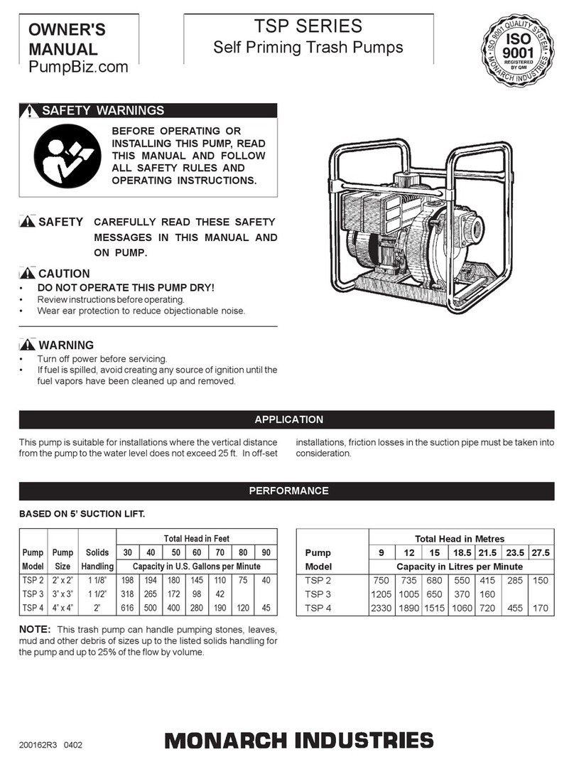
Monarch MIT Series User manual

APPLICATION
BEFORE OPERATING OR
INSTALLING THIS PUMP, READ
THIS MANUAL AND FOLLOW
ALL SAFETY RULES AND
OPERATING INSTRUCTIONS.
SAFETY WARNINGS
SAFETY CAREFULLY READ THESE SAFETY
MESSAGES IN THIS MANUAL AND ON
PUMP.
CAUTION
DO NOT OPPERATE THIS PUMP DRY.
•Review instructions before operating.
• Never exceed recommended RPM.
• Ensure proper rotation as indicated by arrow on pump
casing.
OWNER'S
MANUAL
200027E-R4 0303
MIT SERIES
Self Priming Centrifugal Pumps
These pumps will operate satisfactorily at vertical lifts up to
25 feet when driven at full speed. In offset installations, friction
losses in the suction hose must be taken into consideration.
WARNING
•Ensure input drives are properly aligned and guarded
before operating.
•Keep all shield guards in place (this label is located on
the transmission housing).
INSTALLATION
a ) PUMP LOCATION: The pump should be located on a
firm and level foundation in order to provide the best pos-
sible working conditions. If the pump is not properly
placed or blocked, it is liable to creep due to vibration.
Locating the pump as close as possible to the source
of water supply reduces the friction loss in the suction
hose and provides for maximum capacities.
b ) SUCTION HOSE: The suction hose should be the same
size as that of the pump suction tapping and should be
checked for collapsed inner lining, cuts, breaks, etc. If
the pump is installed any appreciable distance away
form the source of water supply, the suction hose should
be increased in size to reduce friction loss (this also
increases the priming time). To prevent air pockets from
forming in the suction line, the suction hose must always
slope down towards the source of water supply. Thread
compound should be used on all pipe joints and connec-
tions should be thoroughly tightened. A strainer should
be installed on the bottom of the suction hose and should
be properly submerged.
c) WIRING: On electric motor driven units check the rota-
tion of the pump with the arrow on the pump casing. In
the event of wrong rotation, refer to instructions furnished
with motor. The rotation of three phase motors can be
changed by interchanging any two leads to the motor.

2
OPERATION - PRIMING THE PUMP
WARNING: DO NOT RUN THE PUMP BEFORE PRIMING IT, SINCE THE SEAL AND IMPELLER COULD BE
PERMANENTLYDAMAGED.
MAINTENANCE
a) PRIMING: Never operate the pump dry as this may
damage the seal. To prime, remove the priming plug and
fill the pump casing with water. Replace the priming plug
and start the unit. If an exceptionally long suction line is
used, the water in the pump casing may become
overheated or vapor locked. Should this occur, replace
the water in the pump casing with cold water and
continue priming.
b) PRIMING UNDER PRESSURE: Should it be necessary
to prime under pressure, place a check valve on the
discharge of the pump and a pet cock ball type ‘air
bleeder' in place of the priming plug, or an air bleed line
with a gate valve connected to the discharge line (see
Fig. 1). It will then be possible for the liquid to remain in
the discharge pipe and allow the pump to draw the air
bleeder thereby priming itself. In cases where the pump
has to be reprimed often and it is not necessary that a
lot of water is delivered, e.g. draining seepage from
behind a cofferdam, then it is advisable to use a 90° or
45° elbow on the suction line. This enables the pump to
prime quickly and prevents kinking or breaks in the hose.
In cases where a maximum volume of water is required
over a prolonged period of time, the suction line should
be led horizontally to the pump.
c) DRAINING: During freezing temperatures, the pump
should be drained each time it is stopped for any
appreciable length of time. To drain, remove the drain
plug at the bottom of the pump casing and make sure
that the drain hole is not plugged. After all the water has
been drained from the pump casing, the unit should be
operated for a few seconds so that all of the water will be
removed from the impeller.
NOTE: The pump should also be drained after corrosive
liquids have been pumped.
A clogged impeller results in excessive vibration. Should this
occur, the impeller must be cleaned out immediately to avoid
serious damage to the unit.
The MIT20M, MIT20H and MIT40 feature an inspection plug
in the front of the casing for visual inspection at the impeller
eye.
LUBRICATION: Lubricate the bearings with a proper ball
bearing through the grease nipples provided. Do not over
lubricate. Ball bearings require a surprisingly small amount
of grease. Over lubrication causes the bearing to break down
because the grease then tends to churn and produce heat.
If this temperature goes above 200°F, it will break down
causing the bearing to fail.
Gate Valve (min. 3/4")
Check Valve Gate Valve
Discharge
Pump
Air Bleed Line
Suction Pipe
Strainer
FIG. 1

3
REPAIR
TO DISASSEMBLE: MIT-15 (Refer to Fig.2)
1. Remove the four bolts (30) and then remove transmission
head (1).
2. Remove impeller (4) by unscrewing it in a counter-clock-
wise direction.
3. Slip the rotating seal (28) off the shaft.
4. If the stationary seat needs replacing, remove the adapter
plate (3) from the transmission head and press out the
stationary seat.
TO DISASSEMBLE: MIT-20, 30, 40 (Refer to Fig.3)
1. Remove the six nuts (40) and then remove transmission
head (1).
2. Remove the head bolt (29) and collar (13).
3. Remove impeller (4) by unscrewing it in a counter-clock-
wise direction.
4. Slip the rotating seal (28) off the shaft.
5. If the stationary seat needs replacing, remove the adapter
plate (3) from the transmission head and press out the
stationary seat.
TO ASSEMBLE:
1. Clean all parts thoroughly before assembling.
2. Oil rubber cup on stationary seat and push it into the
adapter plate using thumbs only. Make sure the smooth
surface of the ceramic seat faces outwards.
3. Slide the adapter plate over the shaft being very careful
not to damage the stationary seat.
4. Slip the rotating seal on to the shaft with the seal ring
towards the stationary seat.
5. Reassemble the impeller to the shaft.
6. Bolt the transmission head to the pump.
NOTE...Replacing Parts: When replacing either the
body, wear plate, impeller or shaft, the clearance be-
tween the impeller and the wear plate should be
checked. This clearance should be about .020 inches to
.035 inches. If it is less, the impeller will rub against the
wear plate causing undue wear and increase the load. If
the clearance is greater, an increased amount of
recirculation will take place causing a decrease in
efficiency and increase priming time. This tolerance may
be achieved by the addition or removal of gaskets.
FIG.2- MIT 15
FIG.3 - MIT 20, 30, 40

LIMITED MONARCH INDUSTRIES WARRANTY
For one year from date of purchase, Monarch Industries will replace or repair for the original purchaser, free of
charge, any part or parts, found upon examination by any Monarch Industries Authorized Service Depot or by the
Monarch factory, to be defective in material or workmanship or both. Equipment and accessories not manufac-
tured by Monarch Industries are warranted only to the extent of the original manufacturer's warranty. All transpor-
tation charges on parts submitted for replacement or repair under this warranty must be borne by the purchaser.
For warranty service see your nearest Monarch Industries Authorized Service Depot. THERE IS NO OTHER
EXPRESS WARRANTY. IMPLIED WARRANTIES INCLUDING THOSE OF MERCHANTABILITY AND
FITNESS FOR A PARTICULAR PURPOSE ARE LIMITED TO ONE YEAR FROM PURCHASE AND TO
THE EXTENT PERMITTED BY LAW. LIABILITY FOR CONSEQUENTIAL DAMAGES UNDER ANY AND
ALL WARRANTIES ARE EXCLUDED TO THE EXTENT EXCLUSION IS PERMITTED BY LAW.
This warranty is an addition to any statutory warranty.
MONARCH INDUSTRIES
51 Burmac Road, P.O. Box 429
Winnipeg, Manitoba, Canada
R3C 3E4
www.monarchindustries.com
TROUBLESHOOTING GUIDE
PROBLEMS CAUSES
a) Pump fails to prime or primes slowly • Air leaks in the suction line.
•Loose gasket connections due to shrinkage
of gaskets.
•Collapsed or plugged suction hose.
•Check valve may be worn or have dirt lodged
between the rubber flap and the valve seat. This
prevents the valve from retaining a sufficient amount
of water in the pump casing for proper priming.
•Suction lift is too great.
b) Reduced pressure or capacity • Partially collapsed or plugged suction hose.
•Clogged impeller.
•Small air leaks in the suction line.
•Strainer or end of suction hose not properly
submerged.
•Suction line improperly installed permitting air
pockets to form in suction line.
•High suction lift. The greater the suction lift the
lower the capacity and pressure.
•Worn parts such as impeller, wear plate or pump
casing.
This manual suits for next models
2
Other Monarch Water Pump manuals
Popular Water Pump manuals by other brands

Pentair
Pentair Flotec SUB 3S Use and maintenance manual

Shenchen Precision Pump
Shenchen Precision Pump YZ35 Series instruction manual

EINHELL
EINHELL GP JET 1201 INOX operating instructions

Grundfos
Grundfos SQF Installation and operating instructions

Stream
Stream HYDROBOX 900 manual

Edwards
Edwards E2M28 instruction manual