MONTAGUE 36W36 User manual

These instructions should be read thoroughly before attempting installation.
Set up and installation should be performed by qualified installation personnel.
Keep area around appliances free and clear from combustibles.
PLEASE RETAIN THIS MANUAL
FOR FUTURE REFERENCE.
THE MONTAGUE COMPANY
1830 Stearman Avenue
P.O. BOX 4954
Hayward, CA 94540-4954
TEL: (510) 785-8822 FAX: (510) 785-3342
INSTRUCTION MANUAL
MODELS: 36W36, 43W36, 136W36, V136W36, 236W36, 243W36, C36,
C45, C36 SHB, C45 SHB, C36SHBPL, C45SHBPL
Radiglo Heavy Duty Gas
Fired Over Fired Broilers
MONTAGUE

IMPORTANT
SHIPPING DAMAGE CLAIM PROCEDURE
For your protection, please note that equipment in this shipment was carefully inspected and packed
by skilled personnel before leaving the factory. The transportation company assumed full
responsibility for safe delivery upon acceptance of this shipment.
If shipment arrives damaged:
1. VISIBLE LOSS OR DAMAGE - Be certain this is noted on freight bill or express receipt, and
signed by person making delivery.
2. FILE CLAIM FOR DAMAGES IMMEDIATELY - Regardless of the extent of damage.
3. CONCEALED LOSS OR DAMAGE - If damage is unnoticed until merchandise is unpacked,
notify transportation company or carrier immediately, and file “concealed damage” claim with
them. This should be done within fifteen (15) days of date that delivery was made to you. Be sure
to retain container for inspection.
We cannot assume responsibility for damage incurred in transit. We will, however, be glad to furnish you with
the necessary documents to support your claim.
TABLE OF CONTENTS
Important (Cautions and Warnings) .............................................................. Page 1
Introduction .................................................................................................. Page 2 - 3
Installation .................................................................................................... Page 4 - 10
Operation ...................................................................................................... Page 11 - 12
Maintenance .................................................................................................Page 13 - 15
Maintenance Schedule ................................................................................ Page 16
Service .......................................................................................................... Page 17 - 27
Orifice Size Chart - Drill Size ....................................................................... Page 28
Exploded View and Parts List ..................................................................... Page 29 - 32

IMPORTANT
FOR YOUR SAFETY
WARNING
Improper installation, adjustment, alteration, service or maintenance can cause property
damage, injury or death. Read the operating and maintenance instructions thoroughly before
installing or servicing this equipment.
WARNING
Do not store or use gasoline or other flammable vapors and liquids in the vicinity of this or
any other appliance.
NOTE: This manual has been prepared for personnel qualified to install commercial
equipment who should perform the initial field start-up and the adjustments of the equipment
covered by this manual.
NOTE: Instructions to be followed in the event the user smells gas must be posted in a
prominent location. This information may be obtained by consulting the local gas supplier.
1

INTRODUCTION
GENERAL
The Gas Broilers covered in this manual are
manufactured for use with the type of gas
indicated on the nameplate. Some models
include a cabinet, conventional oven, or
convection oven.
Montague Gas Broilers are produced with the
best possible material and workmanship.
Proper installation is essential for safe,
efficient, trouble-free operation.
MODELS
SERIAL NUMBER LOCATION
Always have the serial number of your unit
available when calling for parts and service.
The serial number is on the nameplate that
also includes the model number. A typical
identification plate is shown in Figure 1.
Typical I.D. Plate
(Figure 1)
RECEIVING & INSPECTING THE
EQUIPMENT
Care should be taken during unloading so the
equipment is not damaged while being moved
into the building.
1. Visually inspect the exterior of the package
and skid or container. Any damage should
be noted and reported to the delivering
carrier immediately.
2. If damaged, open and inspect the contents
with the carrier.
3. In the event that the exterior is not
damaged, yet upon opening, there is
concealed damage to the equipment, notify
the carrier. Notification should be made
verbally as well as in written form.
4. Request an inspection by the shipping
company of the damaged equipment. This
should be done within 10 days from receipt
of the equipment.
5. Freight carriers can supply the necessary
damage forms upon request.
6. Retain all shipping materials until an
inspection has been made or waived.
2
Model Features
36W36 Cabinet Based Broiler with
Warming Oven
43W36 Cabinet Based Broiler with
Warming Oven
136W36 Broiler with Conventional
Oven and Warming Oven
V136W36 Broiler with Convection
Oven
236W36 Double Broiler
243W36 Double Broiler
C36 Broiler Only
C45 Broiler Only

INTRODUCTION
3
ORIFICES
Fixed for specified Gas type:
Natural Gas: #33 DMS
Propan Gas: #48 DMS
Manifold Pressure
Natural Gas Propane Gas
6” W.C. 10” W.C.
Gas Inlet Size: 3/4” NPT at lower left rear (all
models).
Model # Burners
(Broilers Only) Natural BTU/h Propone BTU/h Total BTU/h
36W36 2 42,000 ea. 42,000 ea. 84,000
43W36 3 42,000 ea. 42,000 ea. 126,000
136W36 2 42,000 ea. 42,000 ea. 124,000
V136W36 2 42,000 ea. 42,000 ea. 129,000
236W36 4 42,000 ea. 42,000 ea. 168,000
243W36 6 42,000 ea. 42,000 ea. 252,000
C36 2 42,000 ea. 42,000 ea. 84,000
C45 3 42,000 ea. 42,000 ea. 126,000

INSTALLATION
This manual has been prepared for personnel
qualified to install gas equipment, who should
perform the initial field start-up and
adjustments of the equipment covered by this
manual.
Qualified installation personnel are individuals,
a firm, corporation, or company which either in
person or through a representative are
engaged in and are responsible for:
1. The installation or replacement of gas
piping or the connection, installation, repair
or servicing of equipment, who is
experienced in such work familiar with all
precautions required, and have complied
with all requirements of state or local
authorities having jurisdiction. reference:
National Fuel Gas Code, ANSI Z223.1,
section 1.4, latest addenda.
2. The installation of electrical wiring from the
electric meter, main control box or service
outlet to the electric appliance. Qualified
installation personnel must be experienced
in such work, be familiar with all
precautions required and have complied
with all requirements of state and local
authorities having jurisdiction. Reference:
National Electric Code, ANSI / NFPA No.
70, latest addenda.
READ CAREFULLY AND FOLLOW THESE
INSTRUCTIONS
The broiler(s) must be installed in accordance
with local codes, or in the absence of local
codes, with the national fuel gas code, ANSI
Z223.1 latest addenda, including:
1. The appliance and its individual shutoff
valve must be disconnected from the gas
supply piping system during any pressure
testing of that system at test pressures in
excess of 1/2 psig (3.45 kpa).
2. The appliance must be isolated from the
gas supply piping system by closing its
individual manual shutoff valve during any
pressure testing of the gas supply piping
system at test pressures equal to or less
than 1/2 psig (3.45 kpa).
Post in a prominent location the instructions to
be followed in the event the smell of gas is
detected. This information can be obtained
from the local gas supplier.
In the event of a power failure, do not attempt
to operate this device.
IMPORTANT
IN THE EVENT A GAS ODOR IS
DETECTED, SHUT DOWN UNITS AT MAIN
SHUTOFF VALVE AND CONTACT THE
LOCAL GAS COMPANY OR GAS
SUPPLIER FOR SERVICE.
CAUTION
PROVISIONS MUST BE MADE TO ASSURE
ADEQUATE AIR SUPPLY TO UNIT FOR
PROPER BURNER OPERATION.
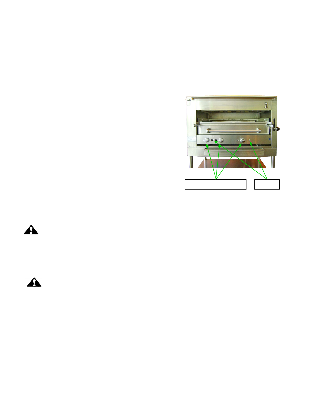
CLEARANCES
The following are minimum clearances from
combustible and noncombustible materials.
With 6” Legs: Suitable for installation on
combustible floors.
Without Legs: For use with special insulated
base on noncombustible floors only.
4
Location Combustible
Construction
Noncombustible
Construction
Back Wall 6” 0”
Left Side 6” 0”
Right Side 6” 0”

INSTALLATION
VENTILATING HOOD
The broiler(s) must be installed under a
properly designed ventilating hood. The hood
should extend at least 6” beyond all sides of
the unit. The hood should be connected to an
adequate mechanical exhaust system.
Information on construction and installation of
ventilating hoods may be obtained from the
“Standard for the Installation of Equipment for
the Removal of Smoke and Grease Laden
Vapors from Commercial Cooking
Equipment”, NFPA No. 96-1987, available
from the National Fire Protection Association,
Batterymarch Park, Quincy, MA. 02269.
It is also necessary that sufficient room air
ingress be allowed to compensate for the
amount of air removed by the ventilating
system. Otherwise, a subnormal atmospheric
pressure will occur which may interfere with
burner performance or may extinguish the
pilot flame. In case of unsatisfactory broiler
performance, check with the exhaust in the
“OFF” position.
ASSEMBLY
Uncrate broiler as near to final location as
possible. For easier and lighter handling of
broiler, remove grids, grid frame, drip tray and
grease container. Remove all packing
materials and accessories from broiler interior.
Legs
Some broilers are mounted on legs.
Screw the legs into the modular stand.
Tightly screw the complete leg assembly into
the mounting holes in the bottom of the broiler
at each corner. If the unit is intended for curb
installation, no legs are provided. The curb
must be noncombustible material.
Ceramic Radiants
Ceramic radiants, Figure 1 & 2, are located on
each side of the burners. Ceramic end pieces
are installed at both ends of each burner
assembly. Five (5) ceramic radiants are
installed on each side of each burner with the
pointed side facing down and the holes facing
up (See Figure 3).
Burner Assembly and Ceramic Radiants,
Top View
(Figure 1)
Burner Assembly and Ceramic Radiants,
Front View
(Figure 2)
5
42 31
1 Frame
2 Ceramic Radiants
3 Burner
4 Ceramic Ends

INSTALLATION
Ceramic Radiant
(Figure 3)
1. Insert ceramic end pieces at front and rear
of the burner frame. Four (4) are required
for each burner.
2. Tilt ceramic radiants sideways to clear
burner and frame assembly, then lower
radiant into position with one flange resting
on burner ledge and one flange resting on
frame edge.
3. Install the remaining ceramic radiants so
that five (5) ceramic radiants are located
on each side of the burner.
LOCATION
Adequate clearance for service and proper
operation must be provided at the front, top,
sides, and back. The combustion air openings
are provided in the front of the unit and must
not be obstructed.
LEVELING
After broiler is positioned, check that
appliance is level both side-to side and front-to
back.
BATTERY ARRANGEMENT
Setting In Place
Model No”s 36W36, 43W36, 136W36, and
V136W36.
Floor Mounted Ranges
1. Place the first unit in the exact position it
will occupy in the battery.
2. Using a carpenter’s level, level the unit
front to rear and side to side. An
unleveled unit will adversely affect
performance. Adjust as follows:
FLOOR INSTALLATION ON LEGS
Level by turning foot on leg.
CURB INSTALLATION
Place shim under the low side. This operation
is important since variations in floors and
curbs are common. Unless units are level,
aligning the gas supply manifold will be
difficult and the units will not fit together tightly.
3. Remove the valve panel from the broiler.
4. Move the unit into position.
5. Engage union nut on manifold with male
fitting on next unit and draw up union nut
hand tight. Be sure appliances meet
together both front and rear. If manifolds
do not align, then units are not level. In
extreme cases it may be necessary to
loosen manifold bolts and adjust.
6. Continue leveling and connecting gas
supply manifolds together until all
appliances in battery are connected.
7. Tighten manifold gas union. Use backup
wrench to prevent manifold from rotating.
Failure to do this may result in damage
to the pilots and gas valves.
GAS CONNECTION
Before connecting the broiler(s) to the gas
supply line, be sure that all new piping has
been cleaned and purged to prevent any
foreign matter from being carried into the
controls by the gas. In some cases, filters
6

INSTALLATION
or drops are recommended. A separate gas
shutoff valve must be installed upstream from
the gas pressure regulator adjacent to the
broiler and located in an accessible are.
It is important that adequately sized piping be
run directly to the point of connection at the
broiler with as few elbows and tees as
possible. Consult your local gas company for
proper piping size and gas pressure. Each
broiler has a 3/4” NPT manifold input located
at the lower left rear of the broiler, Figure 4.
On dual broilers, each broiler must have a
separate regulator.
NOTE: Pipe joint compound or thread sealant
that is used should be resistant to action of
liquefied petroleum gases.
Gas Inlet
(Figure 4)
Install the gas pressure regulator with gas
flowing as indicated by the arrow on the
regulator. The arrow must be pointing in
toward the unit. Use pipe compound or thread
sealant and carefully thread regulator to pipe
so that there is no cross threading, etc., which
could cause leakage.
1. Apply wrench only to the flat areas around
the pipe tapping at the end being threaded
to the pipe to avoid possible damage to the
regulator body which could result in
leakage.
2. Connect the gas supply line from the
service gas shutoff valve to the inlet side of
the gas pressure regulator using 3/4” pipe.
Avoid kinks or sharp bends that could
restrict gas flow.
NOTE: If flexible or semi-flexible connectors
are used, an AGA listed flexible connector
with an I.D. equal to 3/4” pipe must be used.
WARNING
DO NOT USE A DOMESTIC TYPE
FLEXIBLE GAS CONNECTOR.
3. Turn gas shutoff valve on and carefully
check for gas leaks immediately. Do this
before attempting to operate the broiler.
WARNING
TEST ALL PIPE JOINTS FOR LEAKS
BEFORE OPERATING BROILER. THIS
INCLUDES ALL GAS CONNECTIONS THAT
MAY HAVE LOOSENED DURING
SHIPMENT. USE A RICH SOAP SOLUTION
(OR OTHER ACCEPTED LEAK TESTER)
AROUND ALL PIPE JOINTS. DO NOT USE
AN OPEN FLAME. ABSOLUTELY NO
LEAKAGE SHOULD OCCUR, OTHERWISE
THERE IS A DANGER OF FIRE OR
E X P L O S I O N D E PE N D I N G U PO N
CONDITIONS. DO NOT USE UNIT IF
LEAKAGE IS DETECTED.
After piping has been checked for leaks, all
piping receiving gas should be fully purged to
remove air.
GAS PRESSURE REGULATOR
WARNING
DO NOT INSTALL UNIT WITHOUT AN
APPLIANCE REGULATOR.
7
3/4” NPT Gas Inlet

INSTALLATION
THE BROILER IS DESIGNED FOR USE
WITH A PRESSURE REGULATOR. THE
REGULATOR(S) SUPPLIED WITH THIS
UNIT MUST BE USED.
For Natural Gas
This gas pressure regulator is factory adjusted
for 6.0” W.C. manifold pressure. The rated
inlet pressure to the regulators should not
exceed 1/2 psig (3.45 kPa).
For Propane Gas
This gas pressure regulator is factory adjusted
for 10.0” W.C. manifold pressure. The rated
inlet pressure to the regulator should not
exceed 1/2 psig (3.45 kPa).
The broiler is equipped with fixed orifices for
use with a manifold pressure of 6.0” W.C. for
natural gas and 10.0” W.C. for propane gas.
Position the gas pressure regulator outside
the broiler as near to the unit as possible.
CAUTION
THE GAS PRESSURE REGULATOR MUST
BE LOCATED OUT OF THE HEAT ZONE TO
PREVENT DAMAGE TO THE REGULATOR.
ADJUSTMENT PROCEDURE
WARNING
DO NOT ALLOW UNTRAINED PERSONNEL
TO MAINTAIN OR SERVICE THE GAS
PRESSURE REGULATOR.
1. Before adjusting the regulator, check the
incoming gas line pressure into the
regulator. Incoming pressure must be 8.0”
W.C. for natural gas, or 14” W.C. for
propane gas.
2. If incoming pressure is not correct, have
the gas source checked and adjusted.
3. Make sure that the regulator is mounted in
the horizontal position with the arrow going
in the direction of the gas flow.
4. Remove the main burner control valve
knobs, Figure 5.
Control Valve Knobs
(Figure 5)
5. Remove the control valve panel by
removing two screws.
6. Connect a manometer to the pressure tap
provided on the broiler unit gas piping
manifold, Figure 6.
7. Check the manometer reading. The
reading must be 6.0” W.C. for natural gas,
or 10.0” W.C. for propane gas. (DYNAMIC)
8. If incoming line pressure is not correct,
adjust the regulator. Remove the seal cap
on the top of the regulator.
9. Insert a slot screwdriver into the top of the
regulator.
10.Turn the adjust screw clockwise to
increase the pressure, or counter
clockwise to decrease the pressure.
While watching the manometer, turn the
adjustment screw to set proper regulator outlet
pressure to the manifold.
8
Burner Valve Knobs Screws

INSTALLATION
Gas Pressure Tap
(Figure 6)
PILOT INITIAL ADJUSTMENT
Each burner has a separate pilot burner. The
pilot flame is adjusted through access holes in
the valve control panel, Figure 7. Pilot access
is through the broiler panel opening.
Pilot Valves
(Figure 7)
1. Turn the main gas shutoff valve to the on
position.
NOTE: Pilots are on at all times if main shutoff
valve is in the on position and pilot adjustment
valves are open.
2. Light each pilot.
3. Adjust pilot valve adjustment screw so that
each pilot burner has a steady blue flame,
Figure 8.
Pilot Burner
(Figure 8)
Pilot Value
(Figure 9)
BURNER ADJUSTMENT
The efficiency of the broiler depends on a
delicate balance between the supply of air and
the volume of gas at each main burner
resulting in complete combustion. Whenever
this balance is disturbed, poor operating
characteristics occur. An air shutter, Figure 9,
on the front of each main burner controls the
air supply.
9
Manifold Manometer
Connection Pressure
Tap
Pilot Valves Valve Panel
1/2” 1/2”
Adjustment Screw

INSTALLATION
NOTE: Pilots should be lit and properly
adjusted before adjusting the main burners.
1. Lift off the manifold cover to access the air
shutter for each main burner.
2. Turn main burner control valve on fully,
(counterclockwise) in order to adjust
burner flame.
3. Increase the air shutter openings until the
flame on the burner begins to “lift”. Then
close shutter until flame no longer floats,
and lock in place. A yellow streaming flame
indicates insufficient air. Correct this
condition by increasing air shutter opening.
Main Burner Venturi w/ air mixer
(Figure 10)
4. After all main burners are properly
adjusted, reinstall the manifold cover.
5. Turn all main burner control valves fully
clockwise to turn the main burners off.
10

OPERATION
This appliance has been classified as
commercial cooking equipment and must be
operated by qualified and/or professional
operating personnel.
WARNING
THE BROILER AND ITS PARTS ARE HOT.
USE CARE WHEN OPERATING. CLEANING
OR SERVICING THE UNIT.
CAUTION
DO NOT OBSTRUCT THE FLOW OF
COMBUSTION AND VENTILATION AIR TO
THE BROILER. KEEP APPLIANCE AREA
FREE AND CLEAR OF COMBUSTIBLES.
OPERATING CONTROLS
WARNING
IN THE EVENT A GAS ODOR IS
DETECTED, SHUT DOWN UNITS MAIN GAS
SHUTOFF VALVE AND CONTACT THE
LOCAL GAS COMPANY OR GAS
SUPPLIER FOR SERVICE.
The following controls are used for operation
of the broiler, Figure 11.
Burner Control
Used to turn the gas on or off. One control for
each burner.
Grid Height
The grid is set to the desired cooking height
by depressing the ball and adjusting the lever
up or down.
Operating Controls
(Figure 11)
Gas Control
LIGHTING/RELIGHTING PILOT
1. Turn burner valve handle to off position
and wait five (5) minutes.
2. Apply lighted match to pilot burner and/or
check that pilot is burning.
3. R o t a t e b u r n e r v a l v e h a n d l e
counterclockwise to the full on position.
Burner will ignite automatically.
IMPORTANT
DO NOT THROTTLE THE BURNER DOWN.
BURNER MUST OPERATE FULLY OPEN
AT ALL TIMES FOR PEAK PERFORMANCE
4. If pilot becomes extinguished, turn main
burner valve to the off position (fully
clockwise) and wait five (5) minutes before
relighting.
SHUTDOWN
1. Standby: To turn off, rotate main burner
valve handle clockwise.
11
Grid Height ControlBurner Valve Knobs

OPERATION
2. Complete: Turn all gas main burner valves
to off position and turn shutoff valve to
broiler to the off position.
IMPORTANT
NEVER THROTTLE THE BURNER DOWN.
OPERATE BURNER IN FULL ON POSITION.
Grid Height Adjustment
Depress black ball and move lever up or down
to desired cooking height. Figure 11.
12

MAINTENANCE
GENERAL CLEANING
WARNING
THE BROILER AND ITS PARTS ARE HOT.
USE CARE WHEN OPERATING, CLEANING
OR SERVICING THE UNIT.
Lint and grease suspended in the air tend to
collect in passages. Therefore, air openings,
flue ways, and primary air openings, etc.,
should be periodically cleaned to prevent
clogging. The entire broiler should be given a
periodic general cleaning.
Exterior
PAINTED SURFACE
Allow equipment to cool before cleaning
exterior surfaces. Painted surfaces should be
cleaned using a mild soap and warm water
solution on a sponge or soft cloth.
Powder coated, copper, and other such
painted or plated finishes are not covered
under warranty. These finishes are subject to
wear and may begin to discolor and/or chip
within a short period of time. Caution should
be taken when cleaning. Using a mild soap
and water solution will help to maintain the
look and finish.
STAINLESS STEEL SURFACES
Stainless steel is an alloy of iron which
contains chromium. In the process of
manufacturing stainless steel, chromium in the
alloy is used to form the hard oxide coating on
the surface. If this is taken off through
corrosion or wear, it will rust like regular steel.
To remove dirt, grease or product residue
from stainless steel, use water and a mild
detergent if needed, applied with a sponge or
lint-free cloth. Dry thoroughly with a lint-free
cloth.
To remove grease and food splatter, or
condensed vapors that have baked on the
equipment, you can use a (non-abrasive)
commercial cream cleanser or baking soda
and water, applied with a damp lint-free cloth
or sponge. Rub cleanser as gently as possible
(with grain) in the direction of the polished
lines. Do not rub in a circular motion, it will
damage the finish. Rinse surface after
cleaning with a damp lint-free cloth and clean
water. Dry thoroughly with a clean lint-free
cloth. Drying thoroughly will prevent water
spots which are harmful to the finish.
CAUTION
NEVER USE ABRASIVES, POWDERS,
HARSH LIQUIDS, CAUSTICS, OR DYES AS
THEY MAY LEAVE A FILM OR RESIDUE
THAT WILL CLOG THE PORES OF THE
SPECIAL COATING.
Precautions
Strong bleaches tend to corrode many
materials and should not come in contact
with stainless steel sinks or utensils longer
than 30 minutes. When these chemicals
are used, the stainless should be rinsed
thoroughly.
Tincture of iodine or iron should not remain
in contact with stainless surfaces. These
solutions which cause stainless to discolor,
should be rinsed off immediately after
contact.
Some foods, such as mustard, mayonnaise,
lemon juice, vinegar, salt or dressings
containing these, will attack and corrode
stainless. You should never store them in
stainless containers.
Ordinary steel wool pads should not be
used to clean stainless; particles may
lodge in the surface and rust. Allowing the
steel wool pad to rest on a stainless
surface may cause a rusty appearance.
For difficult cleaning jobs such as removing
13

MAINTENANCE
burned-on foods, nylon “sponges” or pads
are recommended. When cleaning a highly
polished, mirror finish, a nylon pad should
be used to avoid scratching the finish.
Gritty, hard abrasives will mar a stainless
finish and are not recommended.
Sharp knives or choppers usually have
hard carbon steel edges and will leave
their mark on stainless surfaces.
With only a little care, your stainless steel
equipment and utensils will remain clean and
bright for years to come. Stainless is hard, rust
-resisting metal that adds beauty and luster to
countless commercial products.
Helpful Hints
To remove streaks, rub stainless steel
surface with olive oil.
To clean and polish, simply moisten a lint-
free cloth with undiluted white or cider
vinegar and wipe clean. Vinegar can also
be used to remove heat stains.
Oil from fingerprints can etch or tarnish
stainless steel, especially mirror-polished
finishes. Wherever stainless steel is
visible, use a glass cleaner to remove
fingerprints at the end of the day, before
the finish is permanently damaged.
Daily
Remove grid racks, drip deflector (below grid
rack), drip tray, and grease container.
Thoroughly wash with mild detergent or soap.
Excessive grease buildup may be removed by
using a mildly abrasive cleanser.
Items to Be Cleaned Daily
(Figure 12)
Griddle/Plancha
SEASONING
Seasoning refers to the process of oil or lard
being baked into the metal to create a non-
stick surface for cooking on a new or recently
cleaned griddle. If a griddle has been
seasoned and food begins to stick, you should
re-season your griddle.
To season follow these steps
1. Apply a coat of food grade oil and turn
griddle on to a low setting (around 200
degrees F) for about 45 min to 1 hour.
2. Raise the temperature of the griddle
(around 300 to 350 degrees F.) and apply
additional layers until surface is slick and
oil no longer seeps into griddle.
14
42 31
1 Drip Deflector
2 Grease Container
3 Drip Tray
4 Grid Rack

MAINTENANCE
3. Repeat this process until griddle forms a
non-stick surface. Once griddle reaches
temperature turn griddle off and let cool.
4. Wipe off excess oil with lint-free cotton
cloth.
CLEANING
After each use, scrape griddle clean with a
griddle scraper when cooked food is
removed to keep surface free of encrusted
material and also prevent flavor transfer.
After each day, while griddle is warm,
clean surface with a griddle stone using a
back and forth motion. For stainless steel,
rub in the direction of the grain to not
damage the surface. Clean grease trough
thoroughly and empty grease container.
Weekly, Allow griddle to cool completely
and clean plate with a foodservice grade
degreaser. Re-season griddle as needed,
or apply a coating of cooking oil to prevent
rust.
A mixture of lemon juice and carbonated
(soda) water can also be used while the
griddle is warm. After applying mixture, rub
griddle stone back and forth to clean
surface. Dry thoroughly and re-season if
needed, or apply a coating of cooking oil to
prevent rust.
15

MAINTENANCE
16
Product Maintenance Schedule
Components Jan Feb Mar Apr May June July Aug Sept Oct Nov Dec
Pilots 1,2 1,2 1,2 1,2
Burner 1,2 1,2
Regulator 1,2 1,2
Grease Container* 2 2 2 2 2 2 2 2 2 2 2 2
T-Couple (CE) 1,4 1,4 1,4 1,4
Injectors 1,2 1,2 1,2 1,2
Gaskets 1,4 1,4 1,4 1,4
Bearings 1,5 1,5 1,5 1,5
Valve (CE) 1,5 1,5 1,5 1,5
Grid Iron* 2 2 2 2 2 2 2 2 2 2 2 2
Top Plate* 2 2 2 2 2 2 2 2 2 2 2 2
Air Mixer 1,2 1,2 1,2 1,2
Interior 2 2 2 2
Gear Mechanics 1,5 1,5 1,5 1,5
Ceramics 1,2,4 1,2,4 1,2,4 1,2,4
Drip Tray* 2 2 2 2 2 2 2 2 2 2 2 2
(1) Inspect (2) Clean (3) Adjust (4) Replace (If needed) (5) Lubricate
*NOTE: Lack of maintenance may result in pre-mature failure of components.
*NOTE: Parts marked with * should be cleaned daily.
*NOTE: Maintenance schedule may vary due to the gas heating value per country.

SERVICE
PARTS REMOVAL & REPLACEMENT
PROCEDURES
Perform the following procedures to remove
and replace parts. To eliminate mistakes when
ordering parts, always provide the following
information:
Model Number
Serial Number
These numbers are located on the nameplate.
CAUTION
TURN OFF THE BROILER GAS VALVE AND
ALLOW BROILER TO COOL BEFORE
REMOVING ANY COMPONENTS
Cover & Panels
CAUTION
TURN OFF THE GAS SUPPLY AT THE
MANUAL SHUTOFF VALVE THAT IS NEXT
TO THE BROILER BEFORE ATTEMPTING
TO LOOSEN ANY GAS CONNECTIONS.
VENTURI COVER
Removal of the venture cover provides access
to the air shutters, pilots, and main burner
orifices.
1. Remove the two screws under the front
edge of the venturi cover.
2. Lift the venturi cover from the broiler.
Venturi Cover
(Figure 13)
Control Panel Cover
Removal of the control panel cover provides
access to the burner valves, pilot valves and
carriage springs.
1. Turn the control valves to the full off
position, then remove the control valve
knobs.
2. Remove the two screws from the front of
the control panel.
Control Panel Cover
(Figure 14)
17
Venturi Cover Screws
Burner Valve Knobs Screws

SERVICE
Drip Deflector
The drip defector is located below the grid
frame and is angled toward the back of the
broiler. Grease dripping onto the drip deflector
runs off the back edge to the drip tray then
flows forward into the horizontal grease
container.
1. Pull the grid frame assembly forward to the
stop.
2. Remove the grids from the frame
assembly.
3. Lift the back edge of the drip deflector to
disengage the drip deflector from the
retaining latch.
4. Slide the drip deflector out at a downward
angle.
5. When reinstalling the drip deflector, be
sure to engage the front end under the
retaining latch.
Drip Deflector
(Figure 15)
Drip Tray and Horizontal Grease Container
The drip tray is located below the drip
deflector. Grease dripping onto the drip
deflector runs off the back edge to the drip
tray then flows forward into the horizontal
grease container.
1. Pull the drip tray straight out the front of
the broiler.
2. Lift the horizontal grease container up and
away from the broiler.
NOTE: When dumping the contents of the
horizontal grease container, be sure to follow
appropriate regulations for disposing of
grease.
Drip Tray & Grease Container
(Figure 16)
Pilot
ADJUSTMENT VALVE
The pilot adjustment valves are located on the
manifold behind the control panel cover.
CAUTION
TURN OFF THE GAS SUPPLY AT THE
MANUAL SHUTOFF VALVE THAT IS NEXT
TO THE BROILER BEFORE ATTEMPTING
TO LOOSEN ANY GAS CONNECTIONS.
18
2 31
1 Grid Frame
2 Retaining Latch
3 Drip Deflector
Horizontal
Grease Container
Drip Tray
Other manuals for 36W36
2
This manual suits for next models
11
Table of contents