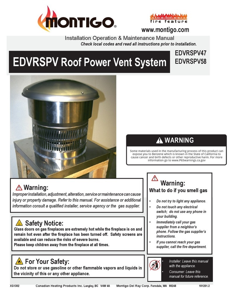
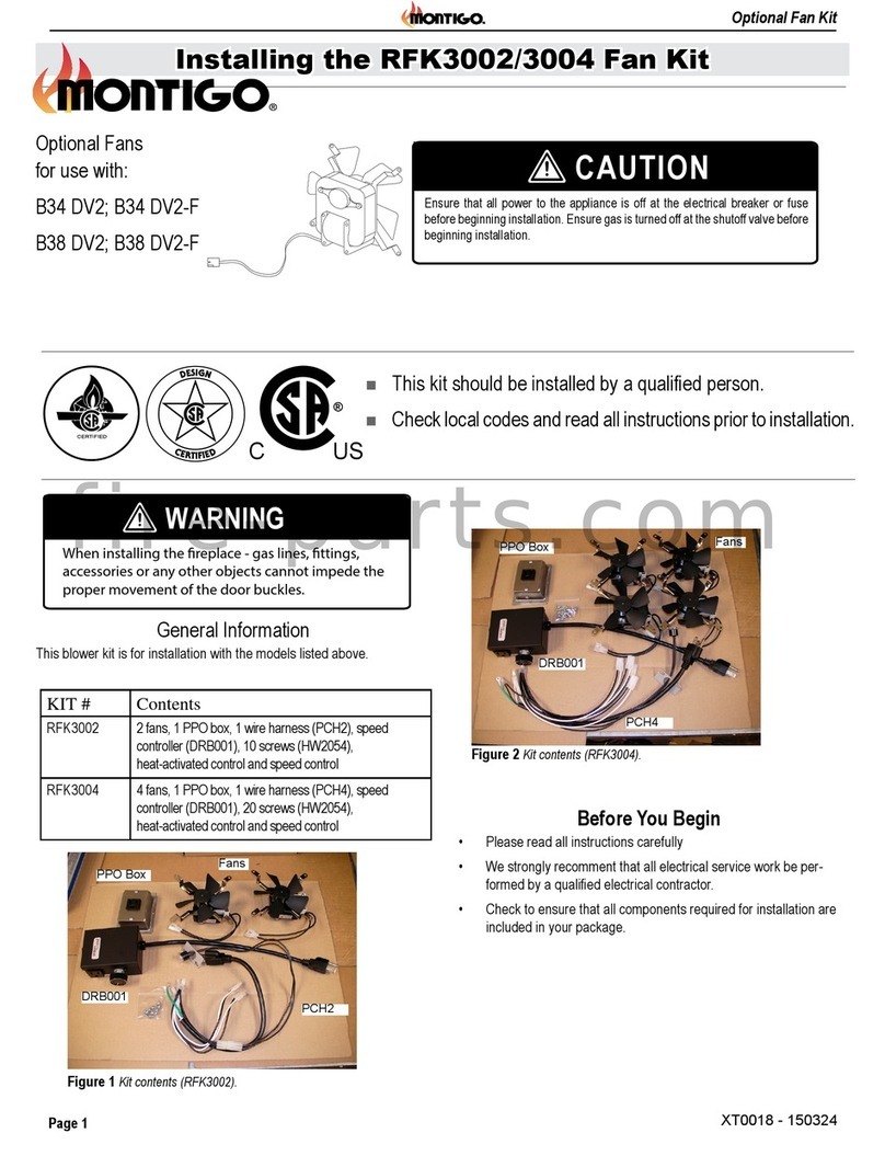
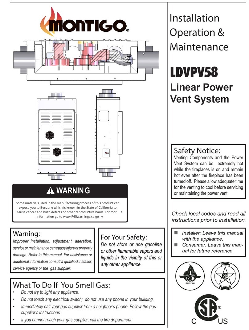
Montigo EDVPV Series Instruction manual

www.montigo.com
XG0700 Canadian Heating Products Inc. Langley, BC V4W 4A Montigo Del Ray Corp. Ferndale, WA 98248 090909
Installation Operation & Maintenance Manual
Check local codes and read all instructions prior to installation.
BF-Series SS Gas Fireplace
EDVPV Wall Power Vent System EDVPV47
EDVPV58
f i r e f e a t u r e
For Your Safety:
Do not store or use gasoline or other flammable vapors and liquids in the
vicinity of this or any other appliance.
Safety Notice:
Glass doors on gas fireplaces are extremely hot while the fireplace is on and remain
hot even after the fireplace has been turned off. Safety screens are available and
can reduce the risks of severe burns.
®
C US
Warning:
Improper installation,adjustment,alteration,serviceor maintenancecan cause
injury or property damage. Refer to this manual. For assistance or additional
information consult a qualied installer, service agency or the gas supplier.
Warning:
What to do if you smell gas
• Do not try to light any appliance.
• Do not touch any electrical
switch; do not use any phone in
your building.
• Immediately call your gas
supplier from a neighbor's
phone. Follow the gas supplier's
instructions.
• If you cannot reach your gas
supplier, call the re department.
• Installer: Leave this manual
with the appliance.
• Consumer: Leave this
manual for future reference.
fire-parts.com

f i r e f e a t u r e
EDVPV47-58 Power Vent System
Part No. XG0700 - 090909
Warning:
Read this manual before installing, operating or troubleshooting this
appliance. Please retain this owner's manual for future reference.
Congratulations
Congratulations on selecting a FireFeature Custom gas fireplace,
an elagent and well designed gas fireplace built to your specifica-
tions. The Firefeature gas fireplace you have selected is designed
to provide the utmost in safety, reliability, and engineering
standards.
As the owner of this new fireplace, you'll want to read and care-
fully follow all the instructions contained in this Installation,
Operations and Maintenance manual. Pay special attention to all
cautions, warnings, and Important warnings.
This owner's manual should be retained for future reference. We
suggest that you keep it with all your other important documents
and product manuals.
The information contained in this owner's manual, unless noted
otherwise, applies to all models, and gas control systems.
Your new FireFeature Custom gas fireplace will give you years of
durable, reliable use. Welcome to the FireFeature family of gas
fireplace products.
Safety Alert Key:
• DANGER! Indicates a hazardous situation which, if not avoided will result in death or serious injury.
• WARNING! Indicates a hazardous situation which, if not avoided could result in death or serious injury.
• CAUTION! Indicates a hazardous situation which, if not avoided, could result in minor or moderate injury.
• NOTICE: Used to address practices not related to personal injury.
•Important: Used to address practices not related to personal injury.
Table Of Contents
Important:
All dimensions, and design specifications are
subject to approval upon quotation of fire-
place and associated equipment.
Congratulations
Safety Alert Key
Table of Contents ..................................................................... 2
Introduction............................................................................... 3
Installation
General Information..................................................... 3
Selecting and Installing the Fireplace........................ 3
Vent Installation............................................................ 4
Power Vent Installation...........................................4 - 6
Wiring ......................................................................6 - 7
Optimizing the External Power Vent........................... 8
Warranty ........................................................................... 9
Appendix
A. Termination Locations .......................................... 10
B State of Massachusetts / Amendment................. 11
Page 2
fire-parts.com

EDVPV47-58 Power Vent System
Part No. XG0700 - 090909
f i r e f e a t u r e
CAUTION!
Due to its high operating temperatures, the appliance
should be located in a well ventilated area / space. See
the clearancespecifications on Page 8.
Children and adults should be alerted to the hazards
of the high surface temperature, which could cause
burns or clothing ignition.
Young children should be carefully supervised when
they are in the same room as the appliance.
Clothing or other flammable materials should not be
placed on or near the appliance.
Introduction
Before You Begin
■Minimumclearances1”fromventtoallcombustiblematerials
mustbemaintained.Clearanceslistedinthereplace’sInstal-
lationOperationandMaintenanceInstructionssupersedethis
number.
CAUTION:
Ensure Perforated Air Holes in the New Pipe Adapter / Restrictor
are not Covered when installing New Pipe Connection.
CAUTION:
When cold air enters the warmer building interior, primarily at the
air intake end, condensation may occur on the exterior of the flex
pipe. To limit this condensation, install insulation over the last
twenty feet of flex pipe. Also, by sloping the last 20'-0" feet of flex
pipe downward toward the exterior of the building, elimination of
most of the condensation problems should occur. Ensure the ter-
mination is securely fastened, and sealed to the flex pipe. Fasten
the termination to exterior of the building with water tight sealant
and the appropriate fasteners.
General Information
This installation guide covers installation of the External Power Vent
System only. This system is designed to allow installation of gas fire-
places that cannot be done with a standard Direct Vent gas fireplace
installation.
Also, read through the fireplace's Installation Operation and Mainte-
nance Instructions, as it must also be adhered to.
Power Cord Harnesses:
EPVH10 -10 foot power cord and harness
EPVH20 -20 foot power cord and harness
EPVH30 -30 foot power cord and harness
EPVH40 -40 foot power cord and harness
EPVH50 -50 foot power cord and harness
EPVH60 -60 foot power cord and harness
EPVH70 -70 foot power cord and harness
EPVH80 -80 foot power cord and harness
EPVH90 -90 foot power cord and harness
EPVH100 -100 foot power cord and harness
Selecting and Installing the
Fireplace
WhenselectingagasreplaceforusewiththeExternalPowerVent
System,takeintoconsiderationthevariousrequirementsandlimita-
tionsintheventing installation sectionforthefollowingmodels:
Models Equipped with Hot Surface Ignition (HSI)
Itisrecommendedthatthissystembeusedwithagasreplace
equippedwithaHotSurfaceIgnitionSystem.Becausethereisnota
pilotinthissystem,thereismoreexibiltyonventingrequirements.
ForexampledownwardverticalvetrunsarepossiblewithanHSI
system,asoutlinedintheVenting Section.
Models Equipped with Millivolt/ Standing Pilot
Ifastandingpilotmodelmustbeused,thenthemillivot wiring har-
ness mustbeinstalled,seetheWiring Section formoreinformation.
Also,downwardverticalvetrunsarenotpossiblewithastandingpilot
system,asoutlinedintheVenting Section.
Installation
Page 3
fire-parts.com

f i r e f e a t u r e
EDVPV47-58 Power Vent System
Part No. XG0700 - 090909
Installation
Figure 1. Typical Venting Installations.
Venting Installation
ItisrecommendedthattheExternalPowerVentSystembeusedwith
agasreplacethatisequippedwithHSI.Wheninstallingthevent-
ing,theinstallationmustadheretotheVentInstallationSectioninthe
replace'sInstallationOperationandMaintenanceInstructions,aswell
asthefollowingguidelines:
■Ensurethattheplannedterminationlocationisacceptableas
showninAppendixA.
■Maximumallowedventrunis100feet.
Figure 2. Multi-elbow Venting Installations.
Multi-Elbow Installations
Multi-elbow installations are possible up to a maximum of six 90°
Figure 3. Downward Venting Installations.
Downward Vertical Venting (HSI Models Only)
Downward venting installations are only possible with gas fireplaces
equipped with Electronic or Hot Surface Ignition (HSI).
Restrictor #1
Max V1 + H1 + V2 + H2 + V3 + H3 Max Elbows
100’ feet six 90
H
V
Elbow 1
Elbow 2
Elbow 3
Elbow 5
Elbow 4
Elbow 6
H3
H2
H1
V1
V2
V3
Restrictor #1
Max V + H Max Elbows
100’ feet six 90
H2
H1
VD
Restrictor #1
Max V1 + H1 + D + H2 + V3 + H3 Max Elbows
100’ feet six 90
Page 4
fire-parts.com

EDVPV47-58 Power Vent System
Part No. XG0700 - 090909
f i r e f e a t u r e
Installation
Installing the Power Vent
Figure 4. FramingtheOpeningforPowerVent
Selecting A Termination Location
Before installing the termination, ensure that the proper air flow restric-
tor is installed as shown on page 5, and check to ensure the planned
termination location is acceptable. For a detailed illustration of allowed
termination locations, see Appendix A.
Installing the External PV Termination
Step 1.Construct a frame for the termination opening to
12 1/2" x 12 1/2".
12 ‰
12 ‰
Figure 5. Assemble the mounting frame, collar, and conduit.
Figure 6. Fastening the conduit to the inner frame
2. Insert the conduit and wiring into the inner mounting frame on
the bottom right of the frame. Install the Collar and ensure that
the conduit can be fastened to the collar and inner mounting
frame as shown in figure 6.
3. Screw the collar in place with three screws as shown in figure 5.
Frame Assembly
Figure 9. Installing the Frame Asssembly.
6. Install and screw the frame asssembly in place, and ensure that
the frame is level.
üüüüüü
Inner Frame Assembly
4. Install the conduit frame around the molex connector as shown in
figure 7a. Screw the collar in place using two screws.
Figure 7b. Installing the Conduit Frame.
5. Assemble the inner frame assembly into the exterior frame and
attach the outer collar to the direct vent pipe that is protruding
through the framed opening.
Inner Frame Assembly
Outer Frame Assembly
Direct Vent Venting
Figure 8. Assembling the inner and outer frames.
Page 5
fire-parts.com

f i r e f e a t u r e
EDVPV47-58 Power Vent System
Part No. XG0700 - 090909
Installation
WARNING:
Montigo will not be held responsible for any water damage
that may occur from not installing the equipment as specified
by this document.
Figure 11.Conduit and Wiring Clearances.
Wiring Installation
Connect the wiring to the external power vent termination as outlined
in the previous section, and connect the wiring to the fireplace as
outlined in the schematic below. Ensure that the proper clearances are
maintaned for the wiring and conduit.
■When installing the wiring it must never run above the vent run
and it must be at least 1" clear of all venting.
1" min.
Vent
Cable
Figure 12.Wiring Diagram for Optional 24V to Millivolt Relay.
White
Red
Black
Milivolt wiring
to Valve
24V wiring from
PV System
Termination
Inner direct vent pipe
6. Install and screw the frame asssembly in place, and ensure that
the frame is level.
7. Install the termination to the frame assembly by first connecting
Figure 10. Securing the Termination to the Frame Asssembly.
Figure 10a. Installing the Sealing Ring.
Page 6
fire-parts.com

EDVPV47-58 Power Vent System
Part No. XG0700 - 090909
f i r e f e a t u r e
Installation
WARNING! If you do not follow these instructions exactly, a re or
explosion may result causing property damage, personal injury or loss of life.
Figure 13.StandardECB005Wiring Schematic for Power Vent System.
Page 7
fire-parts.com

f i r e f e a t u r e
EDVPV47-58 Power Vent System
Part No. XG0700 - 090909
Optimizing the External Power Vent
Installing The Air Flow Restrictor
Prior to installing the termination, ensure that the desired Air Flow
Restrictor has been installed. There are two air flow restrictors, one is
designed for vent runs of 10 to 80 feet and the other is designed for
vent runs of 81 to120 feet, and the downward vertical installations. The
termination comes factory-installed with the1 1/2" 10'-80' restrictor.
Follow these instructions for installing the air flow restrictor:
1. Remove the termination cover by removing the four screws
shown in figure x.
2. Remove the blower assembly from inside the termination.
Remove the three screws that hold the blower assembly in place
and disconnect the wiring connections on the air proving switch,
and the assembly will lift out of place.
Termination
3. Remove the fan gasket to reveal the air flow restrictor. Remove
this restrictor and replace with the alternate air flow restrictor
that came with this system. Replace the gasket and re-install the
blower assembly. Reconnect the wiring for the air proving switch
and replace the termination cover.
Adjusting the Vent Slide
After installing the system, there is a Vent Slide, located on the bottom
of the termination, that is designed for finer adjustments to air flow in
the system, and to alter the flame characteristics of the fireplace.
Locate the vent slide on the bottom of the termination, and loosen the
two screws which hold the vent slide in place. This will allow you to
adjust the vent slide until the desired air flow and flame characteristics
are achieved.
Figure 13. Removing the termination cover.
Termination Cover
Blower Assembly
Figure 14. Removing the blower assembly.
Figure 15. Removing the blower assembly.
Fan Gasket
Air Flow Restrictor
Figure 16. Adjusting the vent slide.
Installing the External Power
Vent System
Page 8
Installation
fire-parts.com

EDVPV47-58 Power Vent System
Part No. XG0700 - 090909
f i r e f e a t u r e
The Warranty
The Companies warrants the Montigo Gas Appliance to be free from defects in materials and workmanship at the time of manufacture. On the Montigo, there is a ten-
year warranty on the firebox and its components, a five-year warranty on the main burner, and a one-year warranty on the pilot burner, gas control valve and fibre logs.
Glass, plated/painted finishes, and refractory lining are exempt.
Remedy And Exclusions
The coverage of this Warranty is limited to all components of the Gas Appliance manufactured by The Companies.
This Warranty only covers Montigo Gas Appliances installed in the United States or Canada.
If the components of the Gas Appliance covered by this Warranty are found to be defective within the time frame stated (see The Companies right of investigation outlined
below). The Companies will, at its option, replace or repair defective components of the Gas Appliance manufactured by The Companies at no charge, and will also
pay for reasonable labour costs incurred in replacing or repairing components. If repair or replacement is not commercially practical, The Companies will, at its option,
refund the purchase price of the Montigo Gas Appliance.
This Warranty covers only parts and labour as provided above. In no case shall The Companies be responsible for materials, components, or construction which are
not manufactured or supplied by The Companies, or for the labour necessary to install, repair or remove such materials, components or construction. All replacement
or repair components will be shipped F.O.B. the nearest The Companies factory.
Qualifications To The Warranty
The Gas Appliance Warranty outlined above is further subject to the following qualifications:
(1) The Gas Appliance must be installed in accordance with The Companies installation instructions and local building codes. The Warranty on this Montigo Gas
Appliance covers only the component parts manufactured by The Companies. The use of components manufactured by others with this Montigo Gas Appliance
could create serious safety hazards, may result in the denial of certification by recognized national safety agencies, and could be in violation of local building codes.
This warranty does not cover any damages occurring from the use of any components not manufactured or supplied by The Companies
(2) The Montigo Gas Appliance must be subjected to normal use. The Gas Appliances are designed to burn gas only. Burning conventional fireplace fuels such as
wood, coal or any other solid fuel will cause damage to the Gas Appliance, will produce excessive temperatures and will result in a fire hazard.
Limitations On Liability
It is expressly agreed and understood that The Companies sole obligation, and purchaser's exclusive remedy under this Warranty, under any other warranty, expressed
or implied, or in contract, tort or otherwise, shall be limited to replacement, repair, or refund, as specified above.
In no event shall The Companies be responsible for any incidental or consequential damages caused by defects in its products, whether such damage occurs or is
discovered before or after replacement or repair, and whether or not such damage is caused by The Companies negligence. Some states do not allow the exclusion
or limitation of incidental or consequential damages, so the above limitation or exclusion may not apply to you. The duration of any implied warranty with respect to
this Montigo Gas Appliance is limited to the duration of the foregoing warranty. Some states do not allow limitation on how long an implied warranty lasts, so the above
may not apply to you.
Investigation Of Claims Against Warranty
The Companies reserves the right to investigate any and all claims against this Warranty and to decide upon method of settlement.
The Companies Are Not Responsible For Work Done Without Written Consent
The Companies shall in no event be responsible for any warranty work done without first obtaining The Companies written consent.
Dealers Have No Authority To Alter This Warranty
The Companies employees and dealers have no authority to make any warranties nor to authorize any remedies in addition to or inconsistent with those stated
above.
How To Register A Claim Against Warranty
In order for any claim under this Warranty to be valid, The Companies must be notified of the claimed defect in writing or by telephone, as soon as reasonably possible
after the defect is discovered. Claims against this Warranty in writing should include the date of installation, and a description of the defect.
Other Rights
This Warranty gives you specific legal rights, and you may also have other rights which vary from state to state.
NOTE: The Companies as stated above refer to - Canadian Heating Products Inc. and/or Montigo Del Ray Corp.
Canadian Heating Products Inc. and/or Montigo DelRay Corp. reserves the right to make changes at any time, without
notice, in design, materials, specifications, prices and also to discontinue colors, styles and products.
Warranty
Page 9
fire-parts.com

f i r e f e a t u r e
EDVPV47-58 Power Vent System
Part No. XG0700 - 090909
Appendix A - Termination Locations
A= clearance to the termination frame above grade, veranda, porch, deck, or
balcony [16 inches (41 cm) minimum]
B= clearance to door, or sides and top of window, that may be opened [16
inches (41 cm) minimum for appliances ≤100 000 BTU/H (30kW)]
C= clearance to bottom of window that may be opened horizontally [36 inches
(92 cm) minimum for appliances ≤100 000 BTU/H (30kW)]
D= no clearance to permanently closed window when installed with approved
glass penetration termination
E= clearance to permanently closed window [16 inches 41 cm recommended
to prevent condensation on window]
F = vertical clearance to ventilated soft located above the termination within a
horizontal distance of 2 feet (61 cm) from the centreline of the termination
[22 inches (56 cm) minimum]
G = clearance to unventilated soft [16 inches (41 cm) minimum to non-combustibles]
[22 inches (56 cm) minimum to combustibles]
H= clearance to outside corner [9 inches (23 cm) minimum]
I= clearance to inside corner [12 inches (31 cm) minimum]
J= * not to be installed above a meter/regulator assembly within
40" (103 cm) horizontally from the centreline of the regulator
K= clearance to service regulator vent outlet [3 feet minimum in the United
States] [*6 feet (1.8 m) minimum in Canada]
L = clearance to non-mechanical air supply inlet to building or the combustion
air inlet to any other appliance [16 inches (41 cm) minimum for appliances
≤100 000 BTU/H (30kW)]
M= clearance to mechanical air supply inlet [*6 feet (1.8 m) minimum]
N= †clearance above paved sidewalk or a paved driveway located on public
property [*7 feet (2.1 m) minimum]
P= clearance under veranda, porch, deck, or balcony
[16 inches (41 cm) minimum‡to non-combustibles]
[22 inches (56 cm) minimum‡to combustibles]
Q= clearance above a roof [24 inches (61 cm) minimum]
R= clearance to adjacent walls and neighboring buildings
[18 inches (46 cm) minimum]
S= clearance from corner in recessed location
[12 inches (31 cm) minimum]
T= maximum depth in recessed location
[48 inches (122 cm) minimum]
U= minimum width for back wall of recessed location
[24 inches (61 cm) minimum]
V= no horizontal clearance between the frames of two terminations that are
level.
W= horizontal clearance between the frames of two terminations that are not
level. [36 inches (92 cm) minimum]
†a vent shall not terminate directly above a sidewalk or paved driveway which
is located between two single family dwellings and serves both dwellings
‡only permitted if veranda, porch, deck, or balcony has an open side that is
equal to or greater than the depth of the enclosed area
* as specied in CGA B149 Installation Codes. Note: local Codes or Regula-
tions may require different clearance.
Page 10
fire-parts.com

EDVPV47-58 Power Vent System
Part No. XG0700 - 090909
f i r e f e a t u r e
Amendment
(Gas Fireplace / Equipment sold in the State of Massachusetts)
5.08:ModicationstoNFPA-54,Chapter10
(1)ReviseNFPA-54section10.5.4.2byaddingasecondexceptionasfollows:
Existingchimneysshallbepermittedtohavetheirusecontinuedwhenagasconversionburnerisinstalled,andshallbeequippedwithamanuallyresetdevicethat
willautomaticallyshutoffthegastotheburnerintheeventofasustainedback-draft.
(2) Revise 10.8.3byaddingthefollowingadditionalrequirements:
(a)Forallsidewallhorizontallyventedgasfueledequipmentinstalledineverydwelling,buildingorstructureusedinwholeorinpartforresidentialpurposes,includ-
ingthoseownedoroperatedbytheCommonwealthandwherethesidewallexhaustventterminationislessthanseven(7)feetabovenishedgradeintheareaof
theventing,includingbutnotlimitedtodecksandporches,thefollowingrequirementsshallbesatised:
1.INSTALLATIONOFCARBONMONOXIDEDETECTORS.Atthetimeofinstallationofthesidewallhorizontalventedgasfueledequipment,the
installingplumberorgasttershallobservethatahardwiredcarbonmonoxidedetectorwithanalarmandbatteryback-upisinstalledontheoorlevelwherethe
gasequipmentistobeinstalled.Inaddition,theinstallingplumberorgasttershallobservethatabatteryoperatedorhardwiredcarbonmonoxidedetectorwithan
alarmisinstalledoneachadditionallevelofthedwelling,buildingorstructureservedbythesidewallhorizontalventedgasfueledequipment.Itshallbetherespon-
sibilityofthepropertyownertosecuretheservicesofqualiedlicensedprofessionalsfortheinstallationofhardwiredcarbonmonoxidedetectors
a.Intheeventthatthesidewallhorizontallyventedgasfueledequipmentisinstalledinacrawlspaceoranattic,thehardwiredcarbonmonoxidedetectorwithalarm
andbatteryback-upmaybeinstalledonthenextadjacentoorlevel.
b.Intheeventthattherequirementsofthissubdivisioncannotbemetatthetimeofcompletionofinstallation,theownershallhaveaperiodofthirty(30)daysto
complywiththeaboverequirements;provided,however,thatduringsaidthirty(30)dayperiod,abatteryoperatedcarbonmonoxidedetectorwithanalarmshallbe
installed.
2.APPROVEDCARBONMONOXIDEDETECTORS.Eachcarbonmonoxidedetectorasrequiredinaccordancewiththeaboveprovisionsshall
complywithNFPA720andbeANSI/UL2034listedandIAScertied.
3.SIGNAGE.Ametalorplasticidenticationplateshallbepermanentlymountedtotheexteriorofthebuildingataminimumheightofeight(8)feet
abovegradedirectlyinlinewiththeexhaustventterminalforthehorizontallyventedgasfueledheatingapplianceorequipment.Thesignshallread,inprintsizeno
lessthanone-half(1/2)inchinsize,“GASVENTDIRECTLYBELOW.KEEPCLEAROFALLOBSTRUCTIONS”.
4.INSPECTION.Thestateorlocalgasinspectorofthesidewallhorizontallyventedgasfueledequipmentshallnotapprovetheinstallationunless,upon
inspection,theinspectorobservescarbonmonoxidedetectorsandsignageinstalledinaccordancewiththeprovisionsof248CMR5.08(2)(a)1through4.
(b)EXEMPTIONS:Thefollowingequipmentisexemptfrom248CMR5.08(2)(a)1through4:
1.TheequipmentlistedinChapter10entitled“EquipmentNotRequiredToBeVented”inthemostcurrenteditionofNFPA54asadoptedbytheBoard;
and
2.ProductApprovedsidewallhorizontallyventedgasfueledequipmentinstalledinaroomorstructureseparatefromthedwelling,buildingorstructure
usedinwholeorinpartforresidentialpurposes.
(c)MANUFACTURERREQUIREMENTS-GASEQUIPMENTVENTINGSYSTEMPROVIDED.WhenthemanufacturerofProductApproved
sidewallhorizontallyventedgasequipmentprovidesaventingsystemdesignorventingsystemcomponentswiththeequipment,theinstructionsprovidedbythe
manufacturerforinstallationoftheequipmentandtheventingsystemshallinclude:
1.Detailedinstructionsfortheinstallationoftheventingsystemdesignortheventingsystemcomponents;and
2.Acompletepartslistfortheventingsystemdesignorventingsystem.
(d)MANUFACTURERREQUIREMENTS-GASEQUIPMENTVENTINGSYSTEMNOTPROVIDED.WhenthemanufacturerofaProductAp-
provedsidewallhorizontallyventedgasfueledequipmentdoesnotprovidethepartsforventingtheuegases,butidenties“specialventingsystems”,thefollowing
requirementsshallbesatisedbythemanufacturer:
1.Thereferenced“specialventingsystem”instructionsshallbeincludedwiththeapplianceorequipmentinstallationinstructions;and
2.The“specialventingsystems”shallbeProductApprovedbytheBoard,andtheinstructionsforthatsystemshallincludeapartslistanddetailed
installationinstructions.
(e)AcopyofallinstallationinstructionsforallProductApprovedsidewallhorizontallyventedgasfueledequipment,allventinginstructions,allpartslistsforventing
instructions,and/orallventingdesigninstructionsshallremainwiththeapplianceorequipmentatthecompletionoftheinstallation.
(3)AfterNFPA-54section10.10.4.2addanewsection10.10.4.3asfollows:
Whenmorethanfourgasappliancesaretobeventedthroughacommongasventorcommonhorizontalventmanifold,aplanoftheproposedventinstallationshall
besubmittedtotheInspectorandtheservinggassupplierforreviewandapproval.
Extraction from: Massachusets Rules and Regulations
5.00:AmendmentsTo2002EditionOfANSIZ223.1-NFPA-54
Appendix B - State of Massachusetts
Page 11
fire-parts.com

Canadian Heating Products Inc.
Langley, BC V4W 4A1
Montigo Del Ray Corp.
Ferndale, WA 98248
XG0700 - 090909
f i r e f e a t u r e
fire-parts.com
This manual suits for next models
2
Table of contents
Other Montigo Fan manuals
Popular Fan manuals by other brands

Bosch
Bosch DWZ1AK1V6 installation instructions

Sonedas
Sonedas 9688463 Instruction guide

Ebmpapst
Ebmpapst G2D180-BD02-07 operating instructions

Continental Electric
Continental Electric CE27616 user manual

Monte Carlo Fan Company
Monte Carlo Fan Company 5CO52 Series owner's manual

S&P
S&P OZEO FLAT H ECOWATT manual