Installation
Page 3
XT0018 - 150324
4. Attaching the Heat Sensor
• This kti includes a heat sensor for automatic control of the
fans. Mount the sensor on the bottom right side of burner
panbase. Remove the two screws located on the top of
the control compartment, just to the right of the gas control
valve. Attach the heat sensor by screwing the mounting
bracket into place using the two screws.
7. Operation
• Turn on electical power at the breaker or fuse.
• Turn on the fan speed controller DRB001 (See Figure 8).
• The fans will automatically switch after the replace's main
burner has been lit and the temperature has risen. The time
lapse between lighting the replace and fan activation will
vary, depending on the model. The fans will automatically
shut off as the replace cools.
• Adjust the fan speed using the knob on DRB001.
Optional Fan Kit
Optional Fan Kits
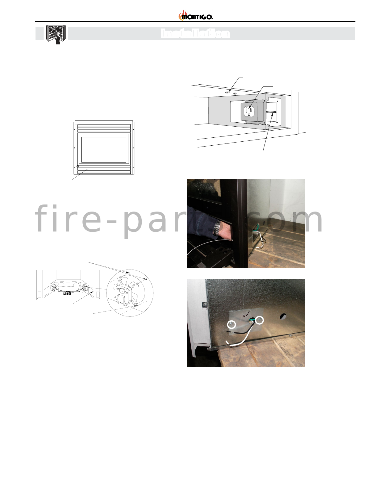
Installing the Power Box
The PPO box connects the fans to the household electrical supply.
In some models this box has been factory-installed, and is located
at the bottom right corner of the fireplace.
If the PPO box has not been factory installed, ensure that the
household electrical supply is shutoff at the breaker or
fuse, and connect the two wire leads from the box to the
household electrical supply. Insert the PPO box into the square hole
in the right-hand side of the control compartment and screw into
place as shown in Figure 4.
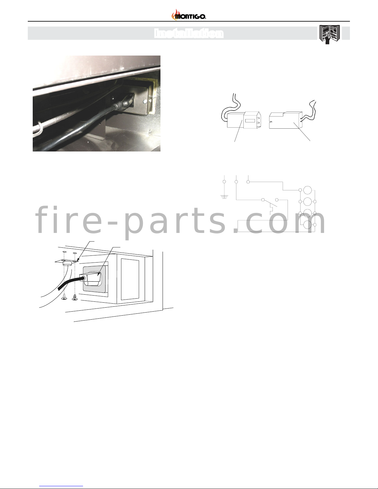
Plug the wire harness' power cord into thePPO box.
Figure 4. Installing the PPO box.
PPO box
To electrical
supply
Heat sensor
locator screw
Attaching the Heat Sensor
Some kits include the optional heat sensor for automatic
control of the fans. Mount the sensor on the bottom right
side of burner panbase. Remove the two screws located
on the top of the control compartment, just to the right of
the gas control valve. Attach the heat sensor by screwing
the mounting bracket into place using the two screws.
Figure 5. Installing the heat sensor.
Page 2 of 2
XG0630 - Rev. 04/99
Operation
1. Turn on electrical power at the breaker or fuse.
2. If the fans are manually controlled (not connected to a heat
sensor), turn on the fans' wall switch to activate the fans.
To stop the fans, turn off the wall switch.
3. If the fans are heat-activated, they will automatically switch
after the fireplace's main burner has been lit and the
temperature has risen. The time lapse between lighting the
fireplace and fan activation will vary, depending on the model.
The fans will automatically shut off as the fireplace cools.
Heat sensor
Power cord
5. Electrical Connections
• Plug each of the fan motor connectors into a quick connector
on the wire harness.
Optional Fan Kits
Optional Fan Kit
General Information
KIT # Description Models Used With:
RFK1002 2 fan kit, manual control B34-DV, B34-DV-2
C34-DV, C34-VF
RFK1003 2 fan kit, heat-activated control B34-DV, B34-DV-2
C34-DV, C34-VF
C38-DV
RFK1006 4 fan kit, manual control C38-DV, C42-DV
RFK1007 4 fan kit, heat-activated control C38-DV, C42-DV
RFK1008 4 fan kit, manual control M38DV-ST
RFK1009 4 fan kit, heat-activated control M38DV-ST
Before You Begin
Pleaseread allinstructions carefully.
We strongly recommend that all electrical service work be
performed by a qualified electrical contractor.
Check to ensure that all components required for installation
are included in your package.
Pull trim outwards
from bottom
Trim
Retainer clip
Control compartment
Figure 1. Removing the lower horizontal trims.
Installation
Accessing the Control Compartment
Remove the lower horizontal trims by placing your fingers under
bottom edge of trim next to retainer clips and pull outward. (See
Inset, Figure 1.)
Install each fan motor with the blades facing the 4" round fan
opening. Attach the mounting legs by screwing into the pilot holes
around the fan opening. Spin the fan blades by hand to ensure
they don't hit the fan opening. (See Figure 2.)
Fan Motor Installation
Figure 2. Cutaway view of control compartment showing fan
motor installation.
Pilot Holes
Mounting Legs
Access for
electrical connections
wire harness connectorfan motor
connector
Electrical Connections
Plug each of the fan motor connectors into a quick connector on
the wire harness. See Figure 3.
115/1/60 Supply
G L1 L2
Figure 3. Electrical Connections.
XG0630 - Rev. 05/99
Page 1 of 2
Figure 8 Attaching power cord to PPO Box.
6. Installing DRB001
• Attach DRB001 Power Cord to PPO box.
• Attach DRB001 to replace oor close to PPO box, and
secure to bottom of shell using supplied velcro.
• Attach PCH 2/4 Power Cord to DRB001 Fan Plug.
• For B34 DV2-F and B38 DV2-F models, attach control box
Power Cord to DRB001 (120V out plug).
Figure 9 Installing the dual receptacle fan speed control
box (DRB001).
Figure 10 Electrical Connections.
fire-parts.com