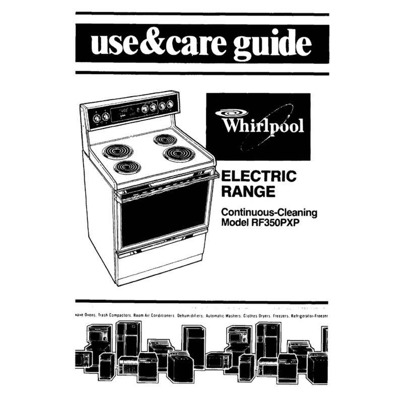
Moorwood Vulcan MV2RCO90-OT-NG User manual

Manual Part No: 933929-01
MD Gas Convection Range Page 1 of 32
Manual Rev No: 1
Country of Destination
GB an IE
MV
MV MV
MV 3
33
3
SERIES
SERIESSERIES
SERIES
GAS CONVECTION
GAS CONVECTIONGAS CONVECTION
GAS CONVECTION
RANGE
RANGERANGE
RANGE
OWNER’S MANUAL
OWNER’S MANUALOWNER’S MANUAL
OWNER’S MANUAL

Manual Part No: 933929-01
MD Gas Convection Range Page 2 of 32
Manual Rev No: 1
IMPORTANT CUSTOMER INFORMATION
Please check the gas tap an thermostat will press an release
freely prior to lighting the burner, as this is part of the unit’s
safety mechanism.
It is particularly important to check this following spillage as
soli ifie fats an carbonise meat juices can impair the
valves correct operation.
IMPORTANT INFORMATION INSTALLATION ENGINEER
Please ensure the customer is ma e fully aware of how the
gas tap an thermostat operate an the importance of
checking its operation aily.

Manual Part No: 933929-01
MD Gas Convection Range Page 3 of 32
Manual Rev No: 1
Mo el No. Pro uct Description Rev. Date Flexible
Hose Size
MV2RCO90-OT-NG
MV2RCO90-OT-NG-C
MV2RCO90-OT-NGV
MV2RCO90-OT-LP
MV2RCO90-OT-LP –C
MV2RCO90-OT-LPV
MV2 Gas Convection Range
MV2 Gas Convection RangeMV2 Gas Convection Range
MV2 Gas Convection Range
6 Burner Hob/Gas Convection Range
With Castors
6 Burner Hob/Gas Convection Range
With VE Pan Supports
6 Burner Hob/Gas Convection Range
With Castors
6Burner Hob/Gas Convection Range
With VE Pan Supports
1
1
1
1
1
1
14/01/08
14/01/08
14/01/08
14/01/08
14/01/08
14/01/08
¾” BSP hose
¾” BSP hose
¾” BSP hose
¾” BSP hose
¾” BSP hose
¾” BSP hose

Manual Part No: 933929-01
MD Gas Convection Range Page 4 of 32
Manual Rev No: 1
INDEX
INDEXINDEX
INDEX
Page
Cover Sheet: 1
Important Information Sheet: 2
Revision Sheet: 3
Inex: 4
Warning Sheet : 5
Intro uction: 6 & 7
General Intro uction 6
Important Note 7
Specification: 8 - 10
Gas Pressure/Connection 8
Overall Dimensions 9
Wiring Diagrams 10
Installation: 11 - 13
Important Note 114
Positioning 11 & 12
Checking & Commissioning 13
User Instructions: 14 - 20
Important Note 14
Operation 15 - 17
Cleaning 18 - 20
Service & Maintenance: 21 - 29
Routine Maintenance 21
Fault Fin ing 22 - 24
Instructions 25 - 29
Spare Parts: 30 & 31
Warranty Cover Sheet: 32

Manual Part No: 933929-01
MD Gas Convection Range Page 5 of 32
Manual Rev No: 1
Warning
Warning
Warning
Warning –
–
–
–
This unit must be mounte on a non
This unit must be mounte on a non-
-
-
-
combustible surface.
Where this appliance is to be positione in close proximity to a wall, partitions,
kitchen furniture, ecorative finishes etc; it is recommen e that they be ma e of
non-combustible material. If not, they shoul be cla with a suitable non-
combustible heat-insulating material, an that the closest attention be pai to Fire
Prevention Regulations.

Manual Part No: 933929-01
MD Gas Convection Range Page 6 of 32
Manual Rev No: 1
INTRODUCTION
INTRODUCTIONINTRODUCTION
INTRODUCTION
This manual contains all the require information to ensure that your new appliance is installe correctly
an that you have all the information necessary to i entify an or er spare parts. It also contains
comprehensive instructions for the user an for cleaning the appliance.
To maintain peak performance, it is recommen e that the appliance be regularly service an that
when or ering spare parts, reference be ma e to the appropriate list quoting the Part No. an the
escription.
THE FITTING OF A NON-STANDARD PART MAY VOID ANY GUARANTEE
.
All work carrie out on this appliance uring installation or servicing must be performe by a competent
person an the connection of the appliance to the gas supply
MUST
be carrie out by qualifie
personnel in accor ance, where applicable, with the relevant regulations.
The siting of the appliance an the connection to the gas/electrical supply must comply with the
GAS
SAFETY (INSTALLATION & USE) REGULATIONS 2000
: the requirements of the
FIRE PRECAUTIONS ACT
1971
; the
HEALTH & SAFETY AT WORK,
etc
ACT 1974
, the
BUILDING STANDARDS (SCOTLAND
)
CONSOLIDATION REGULATIONS 1971
. Detaile recommen ations are containe in British Stan ar s
BS5440: Part 1: 2000, BS5440: Part 2: 2000, BS5588: Part 0: 1996, BS5588: Part 11: 1997 & BS6173:
2001.
The installation must comply with the requirements of Local Authority Regulations an the wiring must
comply with the latest I.E.E. Regulations.
An easily accessible stopcock must be fitte in the gas supply a jacent to the appliance for use in an
emergency. In a ition a fuse isolator must be fitte in the electricity supply.
The etails of the gas supply will be foun on the Data Plate, which is locate on the rear of the flue
upstan /splashback panel.
WARNING
WARNINGWARNING
WARNING: THIS APPLIANCE MUST BE ELECTRICALLY EARTHED
Improvements
The policy of Manitowoc Foo Servi
Manitowoc Foo ServiManitowoc Foo Servi
Manitowoc Foo Service Lt .
ce Lt .ce Lt .
ce Lt . is such that, each pro uct is subject to continual evelopment
an may, therefore, be subsequently improve . The company reserves the right to alter the esign of
any appliance without prior notification an without responsibility to up ate any elivere or in-service
appliance an furthermore, without incurring the responsibility for altering these instructions. In such
circumstances, it may be foun that the appliance etaile herein iffers in certain respects from the one
supplie .
IT IS IMPORTANT, THEREFORE, TO QUOTE THE SERIAL No. AND THE APPLIANCE MODEL No. IN ALL
COMMUNICATIONS WITH THE COMPANY.

Manual Part No: 933929-01
MD Gas Convection Range Page 7 of 32
Manual Rev No: 1
Intro uction
Intro uctionIntro uction
Intro uction (cont.)
Important
Before installing any item please refer to the installation instructions.
We recommen that our authorise service agents carry out all servicing, other than routine cleaning,
an will accept no responsibility for work carrie out by other persons.
For satisfactory operation, parts of catering equipment become hot. Suitable precautions must be taken
to avoi acci ental burns therefore the appliance shoul be positione to minimise the possibility of
acci ental touching. It is the supervisor’s responsibility to warn users to wear suitable protection an to
follow correct operation an cleaning proce ures.
For the etails of your nearest Service Agent for all warranty an repair work, you shoul contact:
The Service Department,
The Service Department,The Service Department,
The Service Department,
Ashbourne House
Ashbourne HouseAshbourne House
Ashbourne House
The Guil way
The Guil wayThe Guil way
The Guil way
Ol Portsmouth Roa
Ol Portsmouth RoaOl Portsmouth Roa
Ol Portsmouth Roa
Guil for
Guil forGuil for
Guil for
Surrey
Surrey Surrey
Surrey
GU3 1LR
GU3 1LRGU3 1LR
GU3 1LR
Tel: +44 (0) 1483 464902
Tel: +44 (0) 1483 464902Tel: +44 (0) 1483 464902
Tel: +44 (0) 1483 464902
Fax: +44 (0
Fax: +44 (0Fax: +44 (0
Fax: +44 (0) 845 301 1461
) 845 301 1461) 845 301 1461
) 845 301 1461
Spares can be obtaine via the Spare Parts Department at the above a ress.
IT IS IMPORTANT TO QUOTE THE SERIAL No. AND THE APPLIANCE MODEL No. IN ALL
COMMUNICATIONS WITH THE COMPANY.
Manual Part No: 933929-01
MD Gas Convection Range Page 8 of 32
Manual Rev No: 1
SPECIFICATION
SPECIFICATIONSPECIFICATION
SPECIFICATION
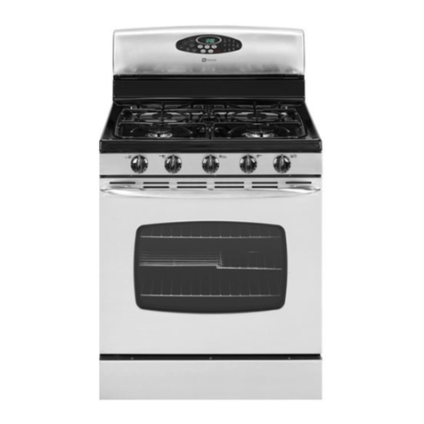
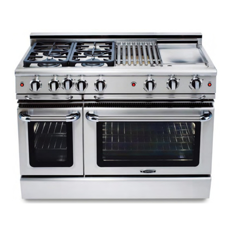
900 6 Burner Gas Hob With Gas Convection Oven
Gas Pressure
Natural Gas 15 mbar (6” wg.)
Propane Gas 37 mbar (14” wg.)
Gas Connection
½” BSP Taper Male (Rp ½”)
When connecting using a flexible hose fit a ¾” BSP hose-900 6Brn Convection Oven Range
Heat Input (Nett)
Injectors
mm
Natural Gas Supply Pressure
20mb.
A juste pressure 15mb
Propane Gas Supply Pressure
37mb.
A juste Pressure 35mb
NG
LP
m
3
/hr
Btu/hr
kW
kg/hr
Btu/hr
kW
Oven 2.44 1.50 0.932 30,025 8.8 0.656 28,606 8.384
Hotplate Burner 2.27 1.32 0.561 20,472 6.0 0.493 20.472 6.0
Total
TotalTotal
Total
Range 4.298 152’857 44.80 3.614 151’438 44.384
Thermostat Calibration
As control knob markings in °C
Electricity Supply
230v Single Phase 50 Hz
Motor Rating (nominal) 320w
Oven Interior Light 30w
Recommen e Fuse Rating 5 Amps
Oven Dimensions
Oven Cavity - 785mm wi e x 530mm eep x 375mm high
Shelf Size - 665mm x 510mm suitable for 2 off 1x1containers
Weight
Range - 130kg

Manual Part No: 933929-01
MD Gas Convection Range Page 9 of 32
Manual Rev No: 1
Specification
SpecificationSpecification
Specification (cont.)
6 Burner Gas Hob with Gas Convection Range
150
945
900
769
347
900
710
876
166
710
180 680 40
150 455
G
G

Manual Part No: 933929-01
MD Gas Convection Range Page 10 of 32
Manual Rev No: 1
Specification
SpecificationSpecification
Specification (cont.)
Wiring Diagram: Range

Manual Part No: 933929-01
MD Gas Convection Range Page 11 of 32
Manual Rev No: 1
INSTALLATION
INSTALLATIONINSTALLATION
INSTALLATION
Important
Your attention is rawn to the
GAS SAFETY (INSTALLATION & USE) REGULATIONS 2000.
This appliance
MUST
be installe by a competent person in accor ance with these an any other relevant
regulations. Users, too, shoul be aware of the regulations governing the use of gas appliances,
particularly with respect to the nee for regular servicing.
The installation wiring of this appliance
MUST
comply with the latest I.E.E. Regulations.
WARNING:
WARNING:WARNING:
WARNING: THIS APPLIANCE MUST BE ELECTRICALLY EARTHED.
PAT TEST: Test voltage shoul be 1250v Max with the spark electro e isconnecte to prevent
amage to the Electronics.
Before Installation
Before commencing installation, remove all packaging materials from the appliance. It is suggeste that
any protective film a hering to the stainless steel panels shoul be left on until installation is complete .
BUT THIS MUST BE REMOVED BEFORE COMMISSIONING OR OPERATING THE APPLIANCE
.
Check the appliance Data Plate (locate on the back of the flue upstan /splashback panel), to ensure the
appliance is suitable for the gas supply available.
Ensure that the floor upon which the appliance is to stan is level an capable of a equately supporting
the weight of the appliance.
TO COMPENSATE FOR SOME UNEVENESS OF THE FLOOR, THE APPLIANCE
FEET ARE ADJUSTABLE.
THE FLOOR MUST BE FIREPROOF
. If it is not, or if any a jacent wall or surface is ma e of a combustible
material, then the installer MUST ensure that the requirements of the
LOCAL FIRE REGULATIONS
are
observe .
Positioning
Place the appliance in position allowing a minimum gap of 150mm (6
”
) at the rear an at least 150mm
(6
”
) between the si es of the appliance an any a jacent wall. If the appliance is being suite then please
refer to the separate instructions. The minimum istance between the hotplate an any overshelf or
ceiling constructe of a combustible material must be 1525mm (60
”
)
A equate ventilation is essential for safe operation of a gas appliance. A supply of fresh air is necessary
for the correct combustion of the gas an there must be a means of exhausting the heat an the
pro ucts of combustion from the kitchen. It is recommen e that the appliance be site below a
ventilating hoo , one preferably connecte to an extractor system incorporating a grease filter.

Manual Part No: 933929-01
MD Gas Convection Range Page 12 of 32
Manual Rev No: 1
Installation
InstallationInstallation
Installation (cont.)
Important Note
The appliance
MUST NOT
be connecte
DIRECTLY
to a flue or ventilating system, although the flue
pro ucts of two or more appliances may be irecte into a common outlet when buil ing suite of
appliances (see separate instructions for suite appliances).
Ensure that the appliance is level in two places – front to rear an si e to si e. To check the level it is
recommen e that a spirit level be place on a shelf in the open oven –
NOT
on top of the hotplate!
Level can be achieve by a justing any or all of the screw in feet in each corner of the base. Turn anti-
clockwise to lower an clockwise to raise the corner.
Gas Connection
Natural Gas
Natural GasNatural Gas
Natural Gas: The size of the supply pipe shoul be no smaller than ½” BSP an an easily accessible
stopcock must be fitte in the gas line a jacent to the appliance. The gas governor provi e with the
appliance
MUST
be fitte in the supply line
BETWEEN
the stopcock an the appliance.
An armoure flexible pipe of a
GAS COUNCIL APPROVED
PATTERN
is recommen e for the installation
of this appliance.
NOTE:
NOTE:NOTE:
NOTE:
Due to the pressure loss through the snap connection fitting on flexi hoses you must fit a ¾”
Due to the pressure loss through the snap connection fitting on flexi hoses you must fit a ¾”Due to the pressure loss through the snap connection fitting on flexi hoses you must fit a ¾”
Due to the pressure loss through the snap connection fitting on flexi hoses you must fit a ¾”
flexible hose
flexible hose flexible hose
flexible hose
Ensure that all the pipes to the appliance are clean an free from swarf etc,
BEFORE
making the final
connection.
Propane Gas
Propane GasPropane Gas
Propane Gas: Follow the same proce ure as that for Natural Gas
EXCEPT
that the Gas Governor
MUST
NOT
be fitte – the Gas Supply Tank or Cylin ers are alrea y fitte with a Gas Regulator.
Leak Test
Clean off any protective film from the stainless steel panels.
AT THIS STAGE, LEAK TEST THE WHOLE SYSTEM. THE GAS SAFETY REGULATIONS
require that
ALL
connections in the gas supply line between the Gas Meter an the appliance is teste for gas leaks.
THIS MUST BE DONE BEFORE COMMENCING TO COMMISSION THE APPLIANCE.

Manual Part No: 933929-01
MD Gas Convection Range Page 13 of 32
Manual Rev No: 1
Installation
InstallationInstallation
Installation (cont.)
Checking an Commissioning
ALTHOUGH EVERY APPLIANCE IS TESTED AND SET BEFORE IT LEAVES THE FACTORY, IT IS
IMPORTANT THAT THE INSTALLER RE-CHECKS CERTAIN FUNCTIONS BEFORE LEAVING SITE.
CHECK THE GAS PRESSURE AT THE APPLIANCE THUS
:
The pressure test point For Ranges it is locate on the manifol rail behin the front control panel,
which is secure by two M5 screws.
Connect a manometer (U Tube) to the test point. Turn on the gas supply an light 3 hotplate burners
plus the oven. Check that the pressure rea ing agrees with that state on the Data Plate.
Go through the oven lighting proce ure, as liste in the
USERS INSTRUCTIONS
, ensuring that all neon
lights work an leave the oven set to 175°C for 20 minutes to ensure that it heats up an that the burner
(an amber light) goes out when the temperature is reache .
SHOULD ADJUSTMENT BE NECESSARY, PROCEED AS FOLLOWS:
-
FOR PROPANE GAS, REFER TO SUPPLIER
On the gas governor: For Ranges it is a separate item.
Remove the cap in or er to gain access to the pressure a justing screw.
Turn the pressure a justing screw clockwise to increase the pressure or anti-clockwise to ecrease it.
When the pressure rea ing is correct, refit the cap to the governor.
Turn the gas supply to the unit
OFF
at the stopcock an isconnect the manometer (U Tube). Ensure that
the pressure test point screw is refitte .
Turn the gas supply to the appliance on at the stopcock an leak test the pressure test point.
Burner Aeration
The aeration of all the burners is fixe an oes not nee a justing. Do not isturb the air combustion
a mission or the combustion pro ucts evacuation on open top burners.

Manual Part No: 933929-01
MD Gas Convection Range Page 14 of 32
Manual Rev No: 1
USERS
INSTRUCTIONS
Important Note
The attention of the user is rawn to the requirements of the
GAS SAFETY (INSTALLATION & USE)
REGULATIONS 2000
. This appliance must be use in accor ance with those, particularly so in respect
of the nee for regular servicing.
See also the sections of this manual referring to Cleaning an General Maintenance.
Safety Note
This appliance is inten e for professional use an shall only be use by qualifie personnel
This appliance is inten e for professional use an shall only be use by qualifie personnelThis appliance is inten e for professional use an shall only be use by qualifie personnel
This appliance is inten e for professional use an shall only be use by qualifie personnel
.
Take care when opening the oven oor while the cooking chamber is still hot. note other Parts an
surfaces of this appliance also become hot uring use.
..
.. It is the responsibility of the kitchen supervisor
to inform an warn every user an kitchen worker of this an , furthermore, to ensure those users wear
an use protective clothing when operating the appliance.
Shoul any a justment or attention be necessary, you are a vise to contact your nearest GAS SAFE
Registere Installer/ Service Engineer imme iately. The nee for regular servicing is etaile in the
GAS
SAFETY (INSTALLATION & USE) REGULATIONS 2000
.
IF YOU THINK THAT GAS IS ESCAPING, ACT IMMEDIATELY. SHUT OFF THE GAS SUPPLY AT THE
METER OR EMERGENCY CONTROL; CONTACT THE SUPPLIER OF YOUR GAS IMMEDIATELY.
MAKE SURE THAT ALL USERS OF THIS APPLIANCE KNOW WHERE THE GAS SUPPLY STOPCOCK IS
LOCATED FOR USE IN AN EMERGENCY.
Improvements
The policy of Manitowoc Foo Service Lt
Manitowoc Foo Service Lt Manitowoc Foo Service Lt
Manitowoc Foo Service Lt is such that each pro uct is subject to continual
improvement.
The company reserves the right to alter the esign of any appliance without prior notification an
without responsibility to up ate any elivere or in-service appliance an furthermore, without incurring
the responsibility for altering these instructions. In such circumstances, it may be foun that the
appliance etaile herein iffers in certain respects from the one supplie .
For further etails or enquires please contact:
Ashbourne House
Ashbourne HouseAshbourne House
Ashbourne House
The Guil way
The Guil wayThe Guil way
The Guil way
Ol Portsmouth Roa
Ol Portsmouth RoaOl Portsmouth Roa
Ol Portsmouth Roa
Guil for
Guil forGuil for
Guil for
Surrey
Surrey Surrey
Surrey
GU3 1LR
GU3 1LRGU3 1LR
GU3 1LR
Tel: +44 (0) 1483 464900
Tel: +44 (0) 1483 464900Tel: +44 (0) 1483 464900
Tel: +44 (0) 1483 464900

Manual Part No: 933929-01
MD Gas Convection Range Page 15 of 32
Manual Rev No: 1
Users Instructions
Users InstructionsUsers Instructions
Users Instructions (cont.)
Pan sizes
The maximum pan size to be use is 34cm an the minimum pan size to be use is 12cm to ensure
satisfactory combustion an stability
Open Hotplates
Lighting Instructions:
1) To turn on an in ivi ual open top hotplate burner, push in the appropriate gas tap knob an
turn it anti-clockwise to the ouble flame position, the “Full On” position. At the same time apply
a lighte taper to light the burner hea .
2) Keep knob epresse for a further 20 secon s until the flame is establishe .
3) If the flame is extinguishe on releasing the knob, wait 3 minutes then repeat steps 1 & 2.
4) To turn own or lower the heat, turn the gas tap knob anti-clockwise from the “Full On” position
until the esire flame height is reache . Turne fully anti-clockwise to the single flame
position, this is the lowest setting.
Note!
Note!Note!
Note!
When first lighting the appliance, after installation or after an exten e shut own perio ,
it may be necessary for the gas control knob to remain pushe in for some time before the
burner will light, owing to the presence of air in the gas line.
To Turn Off:
Turn the gas tap knob fully clockwise (beyon the “Full On” position) to the “Off” position •.
•.•.
•.
Oven
Green Light - Is alight when there is an electrical supply to the unit.
Amber Light - Is on when the oven burner is on. When the amber light goes out the oven has
reache temperature.
Ignition Switch - Initiates the ignition sequence. This takes a few secon s. It turns on the fan &
main burner.
Reset Button - If oven fails to ignite it is necessary to press reset button in or er to repeat
ignition sequence.

Manual Part No: 933929-01
MD Gas Convection Range Page 16 of 32
Manual Rev No: 1
Users Instructions
Users InstructionsUsers Instructions
Users Instructions (cont.)
Oven (cont.)
Lighting Instructions
1) Check that the gas an electricity supplies are turne on an that the “green in icator light” is on.
2) Switch on the Ignition Switch. After a few secon s the controls will automatically go through the
ignition sequence.
3) Once the thermostat is set to the esire temperature the “amber in icator light” will come on an
stay on until the oven reaches temperature, the oven will then automatically cycle on an off at this
temperature.
If, once the thermostat has been turne on, the “amber in icator light” oes not come on, or goes out
before the oven is hot, wait for 3 minutes before pressing the “reset button”.
Note!
Note!Note!
Note! The oven burner epen s on the fan operating for it to work efficiently. To ensure this happens an
air proving (or pressure switch) is fitte , which will allow mains gas to the burner as long as the fan is
operating.
Using the Oven
The oven is provi e with four shelves an four-position shelf supports. Each shelf will take two 1/1-
gastronorm containers.
DO NOT OVERLOAD THE OVEN
. The air must be allowe to move freely aroun
the oven to cook the foo , so leave as much space as possible between ishes an foo .

Manual Part No: 933929-01
MD Gas Convection Range Page 17 of 32
Manual Rev No: 1
Users Instructions
Users InstructionsUsers Instructions
Users Instructions (cont.)
The following gui e is for temperature settings. Cooking times will vary accor ing to foo weight an
size
BUT IT WILL BE SHORTER THAN CONVENTIONAL COOKING
.
Cooking Gui e
Mark No Temp
°
C Temp
°
F
ROASTING
ROASTINGROASTING
ROASTING
Beef joint on bone 2 or 3 140 - 160 284 – 320
Beef joint off bone 3 160 320
Lamb on bone
3
160
320
Lamb off bone
4
140
284
Veal
3 or 4
160
-
180
320
–
356
Pork on bone 6 230 446
Pork off bone 6 230 446
Turkey 4 180 356
Whole Chicken
5 or 6
200
-
230
392
-
44
6
GRILLING
GRILLINGGRILLING
GRILLING
Chicken Portions
6
230
446
Pork Chops 7 250 482
Fillet Steak 7 250 482
Hamburgers 6 230 446
Fish Fingers 3 or 4 160 - 180 320 – 356
Bake Potatoes 5 or 6 200 - 230 392 – 446
Meat Loaf
4
180
356
BAKING
BAKINGBAKING
BAKING
Yeast Brea s - Rolls 4 or 5 180 - 200 356 – 392
Yeast Brea s
-
Loaves
4
180
356
Sweet Rolls & Danish 3 or 4 160 - 180 320 - 356
Biscuits 4 or 5 180 -200 356 - 392
Pizza – frozen or pre-bake 6 230 446
Scones 5 200 392
Sponge Cake
4
180
356
Small Cakes
4
180
356
Puff Pastry 5 200 392
The temperature gui e given above is only inten e as a gui e to assist the user to a apt a temperature
or cooking term in a recipe. The manufacturer has etermine the actual temperature in the oven an it
will not necessarily correspon to the gui e given, but using the gui e will pro uce
the require results
.
It is strongly recommen e that recipes are trie , an that notes of the best results are kept for future
reference.

Manual Part No: 933929-01
MD Gas Convection Range Page 18 of 32
Manual Rev No: 1
Users Instructions
Users Instructions Users Instructions
Users Instructions (
((
(cont.)
Cleaning the Equipment
It will be foun that it takes less time an effort if appliances are cleane every ay, particularly while
they are still warm an before grease an spillage are burnt on.
PROPRIETARY OVEN CLEANER MUST BE USED WITH CARE. THEY ARE HIGHLY CORROSIVE AND MAY
CAUSE DAMAGE TO SURACES AND COMPONENTS.
Open Top Hotplates
Wipe the open top pan support gri s clean of grease an spillage’s regularly (even uring cooking
sessions). A crust of burnt on carbon, coating the pan supports is unsightly, is a health hazar an will
impair cooking efficiency.
Daily: Soak the pan support gri s in a mil solution of a grease issolving agent or etergent
-
DO NOT USE A CAUSTIC CLEANING AGENT
– an wash. Accumulate eposits may be remove by
soaking an then carefully scraping or a fine cleaning paste coul be trie .
SOME PAN SUPPORTS GRIDS ARE VITREOUS ENAMELLED – DO NOT USE CAUSTIC CLEANERS AT ALL.
WIPE OVER WITH A LIGHT COATING OF COOKING OIL AFTER CLEANING AND DRYING.
The burner caps an burner rings may be remove from the open top hotplate burners for cleaning.
Soak an wash in a mil etergent solution, rinse an ry thoroughly before replacing. DO NOT allow
water or cleaning agents to enter the burner venturi.
DO NOT
use caustic cleaners on burner parts.
DO
NOT
scrape or poke the burner port ring, soak an carefully BRUSH clean any stubborn accumulations of
irt.
REPLACE THE BURNER COMPONENTS CAREFULLY IN THEIR CORRECT POSITION
.
Remove the full wi th rip shiel by removing the pan supports an burner caps/rings first. The rip
shiel can be cleane by washing with a mil etergent solution, rinse an ry before replacing. This is
one of those jobs that MUST be carrie out on a aily basis an
IMMEDIATELY
following a spillage.
The Oven
The oven shelves an the oven shelf supports can be remove for cleaning. With raw the shelves in the
normal way, rub them free of grease using an absorbent paper pa an wash in a hot etergent solution.
Rinse an ry before replacing.
The shelf supports are remove by lifting them free from their locating brackets an with rawing them
from the oven interior. They, too, can be washe in a hot etergent solution, rinse an rie before
replacing.

Manual Part No: 933929-01
MD Gas Convection Range Page 19 of 32
Manual Rev No: 1
Users Instructions
Users InstructionsUsers Instructions
Users Instructions (cont.)
Cleaning the Equipment
The Oven (cont.)
Clean the oven interior an the oven oor-lining aily, using a hot mil etergent solution. This is
especially necessary if a spillage has occurre ; meat has been roaste or fruit pies bake . Rinse with
clean water. Stubborn accumulations can be gently scrape off after soaking.
DO NOT USE CAUSTIC OR ABRASIVE CLEANING AGENTS.
Leave the oven rip tray in position while you clean the oven, it will collect all the bits an rips an can
be remove for cleaning at the sink.
Clean stainless steel with soap an hot water or a mil etergent solution. Rinse an ry thoroughly.
DO NOT USE CAUSTIC OR ABRASIVE CLEANERS. DO NO USE ABRASIVE PADS
.
Vitreous enamelle surfaces shoul be wipe clean of grease an spillage’s
BEFORE
they are burnt on.
Use a mil solution or a grease issolving agent or a etergent as a soak an wash. Accumulate
eposits may be remove by soaking an then carefully scraping or by using a fine cleaning paste.
DO NOT USE CAUSTIC CLEANERS
.
On a weekly basis, remove all the oven furniture an the oven bottom panels – the rip tray an the
bottom baffles when fitte .
CLEAN OUT
the bottom compartment – this is the oven burner compartment
an it must be emptie of all loose ebris an carbon eposits.
DO NOT DISTURB THE OVEN BURNER OR ELECTRODE/SENSOR.
DO NOT USE WATER OR A LIQUID CLEANER ON THE OVEN BURNER.
Brush clean using a ry bristle brush.
General Maintenance an Care
This equipment is esigne an manufacture to give you a long, satisfactory service at low cost,
provi e that it is given proper care an attention at all times. Frequent cleaning an regular checking of
correct a justment will be rewar e by re uce operating an maintenance costs, minimum owntime
an regular results from your cooking.
Pilot flames must be of the correct length an be stable an un istorte . All pilot flames must show no
more than a trace of “yellow tipping” an the flames shoul just envelope the en of the flame
electro e/sensor.
DO NOT POKE WIRE INTO PILOT BURNER PORTS OR ORIFICES TO CLEAR THEM OF OBSTRUCTIONS,
SEND FOR A QUALIFIED ENGINEER.

Manual Part No: 933929-01
MD Gas Convection Range Page 20 of 32
Manual Rev No: 1
Users Instructions
Users InstructionsUsers Instructions
Users Instructions (cont.)
Cleaning the Equipment (cont.)
General Maintenance an Care
The flame ports of gas burners must be clean an unobstructe . The user must brush them clean using
a ry bristle brush.
THE UNBLOCKING OF GAS BURNER PORTS IS BEST LEFT TO A QUALIFIED SERVICE ENGINEER.
All gas taps an gas controls must operate smoothly an freely without sticking or jerking.
A
QUALIFIED
SERVICE ENGINEER MUST
carry out re-lubrication.
WE RECOMMEND THAT ALL EQUIPMENT IS SERVICED
WE RECOMMEND THAT ALL EQUIPMENT IS SERVICED WE RECOMMEND THAT ALL EQUIPMENT IS SERVICED
WE RECOMMEND THAT ALL EQUIPMENT IS SERVICED AT LEAST ONCE A YEAR, BUT MAY BE AS
AT LEAST ONCE A YEAR, BUT MAY BE AS AT LEAST ONCE A YEAR, BUT MAY BE AS
AT LEAST ONCE A YEAR, BUT MAY BE AS
FREQUENT AS 6 MONTHS OR LESS IF THE GAS TAPS/THERMOSTAT AND GAS CONTROLS DO NOT
FREQUENT AS 6 MONTHS OR LESS IF THE GAS TAPS/THERMOSTAT AND GAS CONTROLS DO NOT FREQUENT AS 6 MONTHS OR LESS IF THE GAS TAPS/THERMOSTAT AND GAS CONTROLS DO NOT
FREQUENT AS 6 MONTHS OR LESS IF THE GAS TAPS/THERMOSTAT AND GAS CONTROLS DO NOT
OPERATE FREELY. ALL WORK MUST BE CARRIED OUT BY A QUALIFIED SERVICE ENGINEER.
OPERATE FREELY. ALL WORK MUST BE CARRIED OUT BY A QUALIFIED SERVICE ENGINEER.OPERATE FREELY. ALL WORK MUST BE CARRIED OUT BY A QUALIFIED SERVICE ENGINEER.
OPERATE FREELY. ALL WORK MUST BE CARRIED OUT BY A QUALIFIED SERVICE ENGINEER.
SERVICE INTERVALS CAN BE AFFECTED BY SPILLAGE AND SHOULD BE ASSESSED EACH TIME THE
EQUIPMENT HAS BEEN USED.
This manual suits for next models
4
Table of contents
Other Moorwood Vulcan Range manuals