6
SECTION 1 - USERS INSTRUCTIONS
1 USERS INSTRUCTIONS
1.1 INTRODUCTION
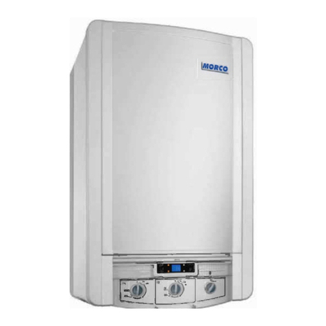
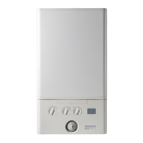
The Morco GB IV is a wall mounted, room sealed, condensing
combination boiler, featuring full sequence automatic spark
ignition and fan assisted combustion.
Due to the high efciency of the boiler, condensate is produced
from the ue gases and this is drained to a suitable disposal
point through a plastic waste pipe at the base of the boiler. A
condensate ‘plume’ will also be visible at the ue terminal.
The Morco GB IV is a combination boiler providing both central
heating and instantaneous domestic hot water.
1.2 SAFETY
Current Gas Safety (Installation & Use)
Regulations or rules in force.
In your own interest, and that of safety, it is the law that this boiler
must be installed by a Gas Safe Registered engineer in the UK, in
accordance with the above regulations.
In other countries the installation must be carried out by a
qualied and competent Gas Installer. In the approved country
the boiler is installed, this must be in accordance with their current
rules in force.
It is essential that the instructions in this booklet are strictly
followed, for safe and economical operation of the boiler.
IMPORTANT. These appliances are UKCA & CE certicated
for safety and performance. It is, therefore, important that no
external control devices, e.g. ue dampers, economisers etc.,
are directly connected to these appliances unless covered by
these Installation and Servicing Instructions or as otherwise
recommended by Morco in writing. If in doubt please enquire.
1.3 ELECTRICITY SUPPLY
This appliance must be earthed.
Supply: 230 V ~ 50 Hz. The fusing should be 3A.
1.4 IMPORTANT NOTES
This appliance must not be operated without the casing
correctly tted and forming an adequate seal.
If the boiler is installed in a compartment then the
compartment MUST NOT be used for storage purposes.
If it is known or suspected that a fault exists on the boiler then
it MUST NOT BE USED until the fault has been corrected by a
Gas Safe Registered Engineer or in other countries a qualied
and competent Gas Installer.
Under NO circumstances should any of the sealed
components on this appliance be used incorrectly or tampered
with.
This appliance can be used by children from 8 years
and above and persons with reduced physical,
sensory or mental capabilities or lack of experience
and knowledge if they have been given supervision
or instruction concerning use of the appliance in
a safe way and understand the hazards involved.
Children shall not play with the appliance. Cleaning
and user maintenance shall not be made by children
without supervision.
Children should be supervised to ensure that they
do not play with the appliance.
In cases of repeated or continuous shutdown a Gas Safe
Registered Engineer, or in other countries a qualied and
competent Gas Installer, should be called to investigate and
rectify the condition causing this and carry out an operational test.
Only the manufacturers parts are to be used for replacement.
1.5 MINIMUM CLEARANCES
Clearances of 165mm above, 100mm below, 2.5mm at the sides
and 450mm at the front of the boiler casing must be allowed for
servicing.
Bottom clearance
Bottom clearance after installation can be reduced to 5mm.
This must be obtained with an easily removable panel, to provide
the 100mm clearance required for servicing.
1.6 TO OPERATE THE BOILER
Refer to Boiler Controls
TO START THE BOILER
Start the boiler as follows:
1. Check that the electricity supply to boiler is off.
2. Set the mode knob (C) to ‘OFF’.
3. Set the Domestic Hot Water temperature knob (A) and Central
Heating temperature knob (B) to ‘e’.
4. Ensure that all hot water taps are turned off.
5.
Switch on electricity to the boiler and check that all controls,
e.g. timer and room thermostat, are on.
6. Set the mode knob (C) to ‘ ’ (winter).
The boiler will commence ignition sequence, supplying heat to the
central heating, if required.
Note. In normal operation the boiler status display (D) will show codes:
00 Standby - no demand for heat.
CH “80
†
”Central Heating being supplied
H “60
†
”
Domestic hot water being supplied
F P “10
†
” Boilerfrostprotection-boilerwillreiftemperatureis
below 5ºC.
†
= temperature shown for example purposes only
During normal operation the burner on indicator (F) will remain
illuminated when the burner is lit.
Note: If the boiler fails to light after ve attempts the fault code
will be displayed (refer to Fault Code page).
1.7 RESTART PROCEDURE
To restart the boiler, press the restart button. The boiler will repeat
the ignition sequence if a heat demand is present. If the boiler
still fails to light consult a Gas Safe Registered Engineer, or in
other countries a qualied and competent Gas Installer.
FOR ANY QUERIES PLEASE RING THE
MORCO CONSUMER HELPLINE : 01482 325456
NOTE. To restart the boiler press the restart button. The boiler will repeat the ignition sequence if a heat demand is
present.


