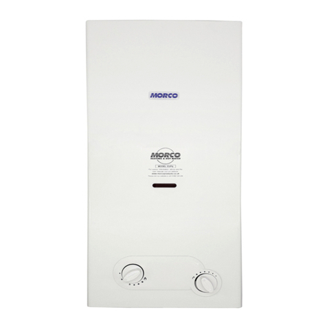
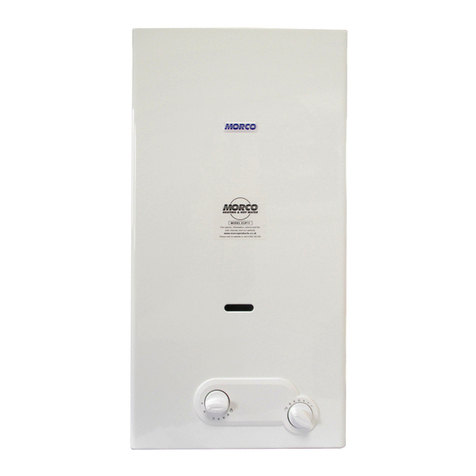
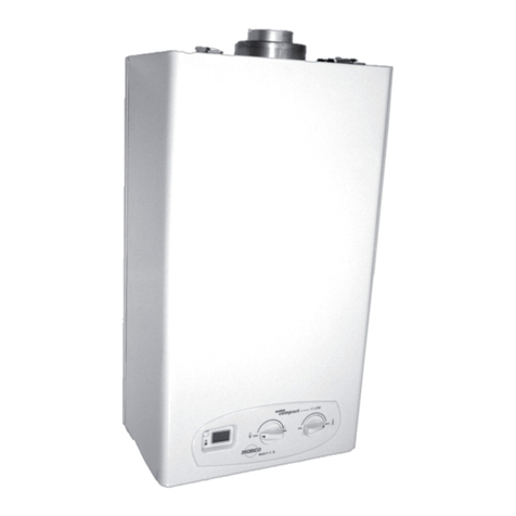
Morco EUP11RS Operating instructions

EUP11RS
Instantaneous gas water heater
User, Installation and Maintenance Manual

QUICK-START GUIDE
POWER ON
Switch the mains electricity supply on to the appliance.
WATER TEMPERATURE ADJUSTMENT
Turn the control knob to the right to increase the temperature and
to the left to decrease it.
POWER OFF
Press and hold theon/off button . As soon as the symbols
begin to flash, release the button.
The appliance will be in the OFF state, the display shows .
RESET – to reset fault codes
Press and hold the reset button . As soon as the display shows
the wording release the button.
If the fault persists, please contact a Gas Safe Engineer or other
qualified person.
Button for
power on/power off/reset Control knob
water temperature
When the product has reached the end of its
serviceable life, it shall be disposed of in an
environmentally friendly way and disposed of
according to the regulations in force.
Separate collection and recycling of the pro-
duct avoid negative impact for environment
and health, and allows recovery of materials,
in order to obtain energy and resources
saving.
WARNING
This booklet contains information relevant to the user as
well as the installer.
The user must read the following chapters: General
Safety, Flue gas device and Operation.
Table of contents
CERTIFICATION 3
GENERAL WARNING AND SAFETY 4
DESCRIPTION OF THE APPLIANCE 5
USE OF THE APPLIANCE 5
COMPONENTS AND DIAGRAMS 7
INSTALLATION 9
TECHNICAL DATA 14
FAULT CODES 15
WINTERISATION 17
WARRANTY AND EXCLUSIONS 18

3
CERTIFICATION
This appliance is manufactured in accordance with the rules of good practice in compliance with current
legislation.
The CE mark on the product means that it conforms to the following European Directives:
• Regulation Gas Appliance (UE) 2016/426
• Low voltage directive 2014/35/UE
• Electromagnetic compatibility directive 2014/30/UE
• European Standard: gas-fired instantaneous water heaters for the production of domestic hot
water EN 26:2015
• Ecodesign directive for energy-related products 2009/125/EC
• Regulation (EU) 2017/1369 setting a framework for energy labelling
• Delegated regulation (EU) no 812/2013
• Delegated regulation (EU) no 814/2013
This appliance is certified to be placed in the following countries in relation to gas type and pressures:
•Cat. I3P (G31 - PROPANE @ 37 mbar): Belgium (BE), Spain (ES), France (FR), Great Britain (GB), Italy (IT), Holland (NL), Ireland (IE)
•Cat. I3B (G30 - BUTANE @ 30 mbar): Belgium (BE), Spain (ES), France (FR), Great Britain (GB), Ireland (IE)
•Cat. I3R (G30/G31 – BUTANE/PROPANE @ 28-30/37 mbar) Spain (ES), France (FR), Great Britain (GB), Italy (IT)
ErP Ready
The appliance complies with the Regulation (EU) 2017/1369 setting a framework for energy labelling.
The energy label carries the information regarding the product’s energy efficiency characteristics.
In this way the end consumer can identify and compare similar products and can make informed choices regarding high efficiency
appliances.
PRODUCT DATASHEET
Morco
EUP11RS
Declared load profile
M
Indoor sound power level dB(A) 52
Water heating energy efficiency class
A
Water heating energy efficiency class %70
Annual fuel consumption
GJ 6
Annual consumption of electric energy
kWh 16
Nitrogen oxide emissions (G30-G31) mg/kWh 60-45

4
GENERAL WARNINGS AND SAFETY
The User, Installation and Maintenance Manual is an integral part
of the product and must therefore be carefully stored and always
accompany the appliance; in case of loss or damage, download
another copy from www.morcoproducts.co.uk.
Use of the appliance requires strictadherence to certain fundamental
safety rules:
In parts of the manual the following symbols are used:
WARNING = for actions that require caution and adequate preparation
PROHIBITED = for actions that MUST NOT be performed
Failure to comply with the recommendations of this manual
and failure to adhere to the instructions included therein by
installers and by the user will invalidate any future warranty
claim.
The safety devices must not be adjusted and in the event
of failure must be replaced with original manufacturer parts.
If the water heater is to be left unattended for any period,
shut off the gas supply. Where the risk of freezing is
anticipated, refer to the winterisation section on page 17.
In case of failure and/or malfunction of the appliance, switch
it off and do not attempt any kind of repair. Contact a Gas
Safe Engineer or other qualified personnel.
At the end of its life span the product must not bedisposed
of as solid urban waste but must be removed to arecycling
centre.
Where the smell of gas is perceived, refrain from using any
electrical switches, telephones or any other object that
could cause sparks. Ventilate the room by opening doors
and windows and turn off the gas supply.
Do not place objects on the appliance.
Do not leave containers of flammable substances in the
room where the appliance is installed.
The use of this appliance by children or inexperienced
persons is not recommended.
The appliance must be used as intended by the manufac-
turer. Contractual and non-contractual liability is excluded
for damage to persons, animals or property, due to installa-
tion, adjustment and maintenance errors or improper use.
Do not use the appliance for purposes other than those for
which it was intended.
Installation of the appliance and subsequent maintenance
must be performed by a Gas Safe Engineer or other
qualified personnel in compliance with the legislation in
force.
The casing can reach high temperatures in the burner
area, with the risk of burns in the event of contact.
Any attempt to carry out a repair in case of failure and/or
malfunction of the appliance should be by a Gas Safe
Engineer.
Maintenance is recommended on an annual basis. Use a
Gas Safe Engineer to carry this out.
Do not clean the appliance and/or its parts with flammable
substances (.g. petrol, alcohols, oil, etc.).

5
DESCRIPTION OF THE APPLIANCE
The Morco EUP11RS is a room sealed, fan flued instantaneous gas water heater. This means its operation is independent of the room it
is installed in as the air for combustion is obtained from outside the home and the flue gases are expelled outside the home. It is
therefore suitable for use in Leisure Accommodation Vehicles (LAVs) such as boats and caravan holiday homes. We do not recommend
the use of this appliance in motorhomes. Ignition of the flame is electronic and will take place automatically when a hot tap is opened.
The appliance does not store hot water.
The display on the appliance may exhibit “AL” if it does not work correctly. The appliance has the ability to self-diagnose certain faults.
Please refer to the fault code table on page 15 before contacting a Gas Safe Engineer. Some of the faults are a temporary and some
are permanent.
The packaging of the water heater includes:
•Wall mounting bracket with screws and plugs
•2 flue restrictor rings - 1 x 43mm and 1 x 45mm
Control panel
Fig. 1- Control panel and display
USE OF THE APPLIANCE
Appliance start-up
Following the necessary checks, proceed with the following
operations:
Electrically power the water heater.
Open the gas isolation valve underneath the water heater.
Ensure that there is a water supply to the heater.
Press the power button .
The display shows:
1. Start-up Parameters
2. Symbols test (display all on)
3. The pre-set water temperature
When you open a hot tap or shower, the display shows the current
water temperature, the symbol (in case hot water request in
progress) and the symbol (in case of burner ON) (Fig. 3).
Service toolgate
Display
Button
Power on
Power off
RESET
Water temperature
control knob
1. Presence of fault
2. Presence of flame (flame symbol)
Flame fault (symbol crossed out)
3. Hot water request in progress
4. Set point temperature
Faults / Alarms
5. Not used
6. Not used
6
1
5
2
MENU EXT MEM
4
3
Display

6
Fig. 2 - Display appliance off (OFF)
Water temperature adjustment
The target water temperature can be set between 37 and 60°C.
Depending upon the incoming cold water temperature and flow
restrictors fitted to hot water outlets, this temperature may not
always be achieved.
Turn the ignition knob clockwise to increase the temperature and
counter-clockwise to decrease it. The symbol flashes and the
display shows the new target temperature set for 5 seconds.
Switching the appliance off
Hold down for about 5 seconds the water heater power off
but
ton .
As soon as the symbols
start flashing, release the button
The appliance will be in the OFF state and the display shows
the symbols . (Fig. 2)
Fig 3 – Display of Appliance during operation
If the water heater is to be left unattended for any period,
drain down the water heater (see Winterisation section),
remove the mains plug from the socket, or isolate the fuse
spur, and shut off the gas supply.

7
COMPONENTS AND DIAGRAMS
Water heater components Hydraulic circuit
Fig. 4 - Water heater components Fig. 5 - Hydraulic circuit
5
Fan
Heat exchanger
6
4
7
Thermistor
Hi-
Limit Stat
Gas valve
Burner
Flow turbine
Hot Water Outlet
Gas Inlet Cold Water Inlet
3
2
1
8
11 10 9
Legend
1. Gas valve
2. Hi-Limit Stat
3. Thermistor
4. Ignition/detection electrode
5. Fan
6. Heat exchanger
7. Burner
8. Flow turbine
9. Cold Water Inlet
10. Gas Inlet
11. Hot Water Outlet
Flow Regulator

8
External dimensions and distances between gas and water connections
Fig. 6 - Installation sizes - Measurements in mm

9
Wiring diagram
Fig. 7 - Wiring diagram
Installation
General Considerations
For the installation engineer
Gas Safety Installation and Use Regulations
It is the law that all gas appliances must be installed by a registered person in accordance with the above regulations.
Failure to install appliances correctly may lead to prosecution. It is in your own interest, and that of safety, to ensure
that the law is complied with.
In addition to the above regulations, this appliance must be installed in accordance with the current IEE wiring
regulations and current ETCI rules for electrical installations.
It should also be in accordance with the relevant recommendations in the current editions of all relevant National
Standards. Your particular attention is drawn to the following relevant standards:
BS 5482 Part 2 Installations in Caravans and Non-Permanent Dwellings
PD 5482 Part 3 Installations in Boats
BSEN 1949 Installation of LPG System for Habitational Purposes in Leisure
Accommodation Vehicles
BSEN 721 Leisure Accommodation Vehicles-Ventilation Requirements
BS EN ISO 10239 2008 Small Craft, LPG Systems
IMPORTANT: Manufacturer’s instructions must NOT be taken in any way as overriding statutory regulations.
Legend
EL Ignition Electrode
TR Spark Generator
F Fan
FX Flow Turbine
LT Hi-Limit Stat
SP Thermistor
GV Gas valve
B
BLUE
BLUE
BLUE
BLUE
BROWN
BROWN
BROWN
BROWN
BROWN
BROWN
BLACK
BLACK
BLACK
VIOLET
VIOLET
LIGHT BLUE
VIOLET
GREY
PINK
RED
YELLOW
WHITE

10
Wall mounting
Precautions
The appliance must be installed on a suitable wall that allows for the
installation of a horizontal or vertical flue.
- To allow maintenance operations, leave the minimum distances
shown (Fig. 8) around the appliance.
Location
- If the appliance is positioned in areas exposed to the risk of frost,
the water heater must be disconnected and drained of water – see
Winterisation section.
Fig. 8 - Minimum required distances
Connection of the water heater to the water, gas and flue
gas exhaust systems and the room where the heater is to
be installed must comply with the rules and regulations in
force, see above.
Following installation of the water heater, check the tight-
ness of all the gas and water connections.
Installation of this appliance should be carried out by a Gas
Safe Engineer in the UK or other qualified personnel.
Verify if the available gas type and pressure corresponds
to that indicated on the appliance data plate.
Install an isolation valve on the gas supply, upstream of the
appliance, in a visible and accessible position and as close
as possible to the appliance.
Check the water hardness (200 ppm maximum allowable
total hardness). If it exceeds 200 ppm a scale reducing
device must be fitted upstream from the appliance for
softening water. Hard water will slowly reduce the
operational efficiency and reliability of the water heater.

11
Support bracket
Having established the position of the appliance fix the wall
mounting bracket in the appropriate position.
The most common installation is shown below in Figure 9.
Fig. 9 - Support bracket and horizontal flue rear exit location
Electrical connection
Gas connection
The diameter of the gas pipes should be suitably sized to
accommodate for all of the gas appliances in the home.
A gas isolation valve should be fitted to the gas inlet of the
appliance or an inline isolation valve fitted close to the appliance on
the supply pipe.
For initial start-up of the appliance, the following checks must be
carried out by a Gas Safe Engineer.
1. Check the gas inlet pressure is 37mbar (or relevant pressure for
the country that the appliance is being commissioned in) with all
other gas appliances in the Holiday Home working at maximum.
2. Turn on the water supply to the water heater and check for leaks.
3. Turn the tap on full and check the flow and temperature according
to the Technical Data on page 14. You may have to do this by
disconnecting the hot water feed to the plumbing pipework as
there may flow regulators fitted to certain taps.
4. Check burner pressure as in Technical Data on page 14.
5. Adjust control knob water temperature and check temperature of
water changes at the tap.
6. Check with a calibrated Flue Gas Analyser that your ratio is
< 0,025 % (or 250 ppm) CO Dry Air Free
Do not use the gas pipes as electrical appliance earthing devices.
Water connection
Power the appliance via a double pole switch.
N.B. no responsibility is accepted for damage to persons, animals
or property caused by failure to earth the appliance and the creation
of an electrical installation that does not comply with current
standards.
For the main power supply of the appliance from the mains, the use
of adapters, multiple sockets and/or extension cords is not permitted.
The use of any component that uses electricity involves the
observance of a number of fundamental rules such as:
- Do not touch the appliance with wet parts of the body and/or bare
feet
- Do not pull the electrical cables
- Do not leave the appliance exposed to atmospheric agents
(rain, sun, etc.)
- Do not allow the appliance to be used by children or
inexperienced persons.
Where the appliance will not be used for a certain period of time, it
is advisable to disconnect the power supply to all the system
components that use electricity.
Connect the water heater to the water mains and fit a water shut-off
valve prior to the appliance.
Looking at the front of the appliance, the cold water inlet is on the
right and the hot water outlet is on the left.
The minimum distance between the water heater hot outlet and the first
tap or mixer must exceed of 0.5m.
Electrical current with 230V voltage
Before any work on the electrical equipment, always
disconnect the 230V voltage.
Water temperatures >50°C may cause severe burns.
Verify the water temperature before using.
Service Inlet
Inlet Gas Pressure
Outlet Gas Pressure

12
FLUE TERMINAL POSITION
The heater must be installed so that the terminal is exposed to the external air. It is important that the position of the terminal allows
free passage of air across it at all times. It is essential to ensure that the products of combustion discharging from the terminal cannot
re-enter the building or vehicle, through ventilators, windows, or other sources of natural air infiltration, such as other flues etc, with the
exception of doors, but not the opening windows thereof.
The minimum acceptable dimensions from the terminal to obstructions and ventilation openings is as follows:
Directly below an opening fixed vent or window etc ...............300mm
Adjacent to an opening fixed vent or window etc .....................300mm
Below gutters ........................................................................75mm
From a vertical drain pipe ......................................................75mm
From an internal or external corner .......................................300mm
Where the terminal is fitted in a position to which children, the elderly, or disabled people have access (less than 1.5m above steps,
decking or ground), a suitable terminal guard should be fitted. In certain weather conditions the terminal may emit a plume of steam.
Flue - Exhaust Gas and Air Inlet
The appliance can be used with a horizontal or vertical flue system. The respective part codes are RSF503 and RSF545. The Flues
feature concentric tubes, the inner 60mm Ø tube is for the flue exhaust gas and the outer 100mm Ø tube is for the air inlet.
Current flue standards should be adhered to and the flues fitted must be the above supplied by Morco Products as these are CE certified
for use with the appliance.
TYPE C: Horizontal coaxial exhausts
In this configuration, air intake and combustion product exhaust
is outside the home through concentric pipes.
Coaxial exhausts can be faced in the direction most appropriate
to room needs, meeting the methods and lengths indicated
in the following table.
The reference quotas for where to trace wall hole for the
support bracket are provided in figure 10.
TYPE C: Vertical coaxial exhausts
Use the vertical exhaust manifold and, if necessary, the
relevant extensions, observing the maximum admitted lengths
as indicated in the table.
Fig. 10 - Type C exhaust dimensions
17 7
COAXIAL EXHAUSTS

13
Fig.11 - Top view with distances Fig. 12 - Maximum pipe length (see following table)
The
90° appliance
Length
pipes/metres
output curve load
loss should
NOT
be
calculated
Maximum considered length
Reference table for maximum workable length based on the selected exhaust type
Flue Type
Length of Flue (m)
Flue Restrictor
(mm)
Reduction in allowable length for
each additional elbow
This excludes the 90° elbow
connected to the appliance
45°
90°
Horizontal Co-axial
Flue
up to 1m
Ø43mm
1m
1.4m
1 - 2.7m
Ø45mm
1m
1.4m
2.7 – 5.5m
None Installed
1m
1.4m
Vertical Co-axial Flue
up to 2m
Ø43mm
1m
1.4m
2 - 3.7m
Ø45mm
1m
1.4m
3.7 - 6.7m
None Installed
1m
1.4m
14 2
5 9
Warnings before ignition
Please remember that appliance installation, first ignition, maintenance and repairs must be performed by
qualified personnel. In the UK this is a Gas Safe Engineer.
Before turning on the appliance, proceed with suitable checks:
•Ensure the gas system seal is good (according to current regulations)
•Ensure gas type and pressure match those stated on the data plate
•Ensure the installation meets current local regulations
•Ensure the flue meets current regulations
•Check connections with the electrical mains, Live and Neutral, polarity and grounding connections
•Check the mains pressure as indicated in the next paragraph.
The
90° appliance output
curve load loss should
NOT
be calculated

14
TECHNICAL DATA
EUP11RS
kW - kcal/h
Nominal heat input (Qn)
21,5 - 18.490
Nominal output power (Pn) 19,3 - 16.604
Minimum heat input (Qm) 9,5 - 8.170
Minimum output power (Pm) 8,6 - 7.353
GAS TYPE
PROPANE
BUTANE
G31
G30
P.C.I. (15° C 1013 mbar) MJ/m388,00 116,09
WI (15° C 1013 mbar) MJ/m370,69 80,58
Consumption (15° C 1013 mbar)
1,67 kg/h
1,70 kg/h
Maximum burner pressure mbar 36,4 28,3
Minimum burner pressure mbar 8,0 6,1
N. nozzle
Ø Main burner nozzle Nr/mm 18x0,50
+4x0,48
NOx emissions (according to EN26:2015 on HS)
mg/kWh
45,1
60,3
Ø Gas connection
“
3/4
BE-FR-GB-IE-IT-ES-NL category - nominal feed pressure
I3P - G31: 37 mbar
BE-ES-FR-GB-IE category - nominal feed pressure
I3B - G30: 30 mbar
ES-FR-GB-IT category - nominal feed pressure
I3R - G30/G31: 28-30/37 mbar
FUMES EXHAUSTION EUP11RS
G31 G30
Flue gas mass flow rate (min-max)
kg/h
34,005-53,020
42,465-63,644
Flue temperature (max-min)
°C
159 - 96
165 - 101
Air capacity Nm3/h 40,741 49,112
Ø flue gas release tube
mm
100/60
FAN PERFORMANCE EUP11RS
Residual head of boiler without pipes
Pa
71
ELECTRICAL CIRCUIT EUP11RS
Power supply voltage
V - Hz
230 – 50
Electric power
W
41
Degree of Protection
IPX5D
INSTALLATION SITE TEMPERATURE EUP11RS
Minimum working temperature
°C
3
WATER EUP11RS
Domestic water flow limiter
l/min
8
35°C temperature rise above ambient l/min 8
Minimum ignition flow l/min 2
Selectable water temperature
°C
37-60
Minimum pressure
bar
0,13
Maximum pressure bar 10
Ø water connections
1/2”
DIMENSIONS AND WEIGHTS EUP11RS
Height
mm
617
Width
mm
304
Depth
mm
222 (238 with aesthetic)
Weight
Kg
14
Note: cold water temperature of reference 15°C.

15
FAULT CODES
Should the appliance shut down the display shows the letters
followed by a fault code which should be consulted in relation to
the shutdown.
Two types of shutdown are possible:
1. Temporary shutdown (non-permanent). The fault code
flashes, shutdown is automatically removed upon resolution
of the problem that caused it. If the fault persists, shutdown
switches from temporary to permanent.
2. Permanent shutdown (lock), the fault code is steady. In this
case the appliance does not start again automatically and the
issue will need to be resolved by a Gas Safe Engineer or
other qualified personnel.
Below are listed the types of alarms, their typical display viewsand
the solutions to reset the appliance:
Fig. 13 - Display appliance shutdown
Display Alarm type Solutions
Permanent shutdown
Flame control module shutdown alarm
Flame control electronic fault alarm
Press and hold the reset button . As soon as the letters
appear on the display, release the button.
The appliance automatically restarts. If the fault persists, request the
assistance of a Gas Safe Engineer or other qualified personnel.
Permanent shutdown
Limit thermostat alarm Press and hold the reset button . As soon as the letters
appear on the display, release the button.
The appliance automatically restarts. If the fault persists, request the
assistance of a Gas Safe Engineer or other qualified personnel.

16
Temporary shutdown
Parasitic flame alarm Request the assistance of a
Gas Safe Engineer or other qualified
personnel.
Permanent shutdown
Interrupted modulator cable alarm Press and hold the reset button . As soon as the letters
appear on the display, release the button.
The appliance automatically restarts. If the fault persists, request
the assistance of a Gas Safe Engineer or other qualified
personnel.
Permanent shutdown
Alarm in case of 5 consecutive resets
To reset the appliance, disconnect the appliance for 6 minutes
and then reconnect the electrical voltage.
Press and hold the reset button . As soon as the letters
appear on the display, release the button.
If the fault persists, request the assistance of a Gas Safe
Engineer or other qualified personnel.
Temporary shutdown
Low Voltage Alarm <180V AC Wait until automatic reset of the water heater.
If the fault persists, request the assistance of a Gas Safe
Engineer or other qualified personnel.
Temporary shutdown
Incorrect mains frequency detection alarm Wait until automatic reset of the water heater.
If the fault persists, request the assistance of a Gas Safe
Engineer or other qualified personnel.
Permanent shutdown
Flame loss for more than 3 consecutive
times alarm
Request the assistance of a
Gas Safe Engineer or other qualified
personnel.
Temporary shutdown
Button alarm This is displayed when you keep pressed the button for more than
30 seconds, once the button is released the fault disappears.
Permanent shutdown
Valve calibration request Request the assistance of a
Gas Safe Engineer or other qualified
personnel.
Permanent shutdown
Alarm as domestic water Delta T not
reached upon power on
Request the assistance of a
Gas Safe Engineer or other qualified
personnel.
Permanent shutdown
PCB Fault Request the assistance of a
Gas Safe Engineer or other qualified
personnel to replace.
Permanent shutdown
Alarm for combustion problem upon power
on Press and hold the reset button . As soon as the letters
appear on the display, release the button.
The appliance automatically restarts. If the fault persists, request
the assistance of a Gas Safe Engineer or other qualified
personnel.
Permanent shutdown
Shutdown due to persistent poor
combustion
Request the assistance of a Gas Safe Engineer or other qualified
personnel.
Temporary shutdown
Alarm due to poor combustion. Also fault
84
Request the assistance of a Gas Safe Engineer
or other qualified
personnel.

Permanent shutdown
Alarm fan hall effect speed sensor Request the assistance of a
Gas Safe Engineer or other qualified
personnel.
Display
High temperatures Request the assistance of a Gas Safe
Engineer or other qualified
personnel.
Permanent shutdown
Software fault alarm, PCB start-up Request the assistance of a
Gas Safe Engineer or other qualified
personnel.
WINTERISATION
Winterisation of Holiday Homes That Have a Water Heater
Fresh water freezes at 0°C and expands by 9% with a significant force that will destroy:
•Pipe work
•Water heater components
•Taps, and shower valves
DRAIN DOWN
If you leave fresh water in your caravan system over the winter you will run the risk of damage. This can only be avoided by removing the
fresh water from the system – we call this a “drain down”. You may wish to drain down the fresh water system yourself using the
procedure in the next section but we STRONGLY RECOMMEND that you have this carried out by an experienced engineer as many
caravan systems can only be completely drained by blowing the water out and this requires specialist equipment. View the £50-£60
charge for a drain down as a mini insurance policy and always ask the engineer if he has equipment to blow the water out. The two most
common parts to be damaged by frost are the shower valve and the water control assembly in a water heater and the costs to replace
these are around £100 each.
Drain Down Procedure – without specialist equipment
•Turn off the fresh water supply stop cock outside the Holiday Home
•Disconnect the fresh water feed outside the home if possible as this protects from flooding due to stop cock failure
•Open all hot and cold taps and shower valves and place the shower head in the tray
•Use the Holiday Home Owner’s Handbook to locate all the fresh water drain cocks under the van – some of these may not be
obvious
•Open these drain cocks
This procedure does not guarantee that all the fresh water will leave the system. Most modern homes have double check valves in the
TMV2 shower mixers and these trap fresh water and stop the flow of water around the system once the drain cocks and taps are open. It
may appear that all the water has left the system, but beware! This pitfall can be avoided by removing the shower mixer valve/valves
from the system after the cold water supply has been switched off and the drain cocks opened. Many manufacturers provide access
panels and these may make the removal of shower mixers easier. Removal of some shower mixers requires the use of special tools.
In addition, pipe work layouts can cause air locks leaving water inside vulnerable components such as the water heater or shower mixer.
Re-commissioning the home is a reverse of the above procedure.
This drain down procedure may work but the only way to be sure is to blow the water out using compressed air at 3 bar maximum
pressure.

WARRANTY
The water heater is guaranteed against manufacturing defects for one year from first commissioning date. However, the guarantee
is subject to proof of commissioning in accordance with the gas safety (Installation and Use) act of 1998. The guarantee does not
cover defects caused by lack of maintenance.
Morco Products Ltd. warranty will cover parts and labour if the appliance has been fitted as part of the original equipment in a
caravan holiday home or leisure accommodation vehicle.
Appliances distributed as non-original equipment either directly from Morco Products Ltd. or other merchants are subject to a return
to base policy for repair and return.
As an alternative to returning the appliance for repair we will supply spare parts and advice for defective appliances on the provision
that we can talk to the competent registered gas engineer involved in the fitting or repair of the defectiveappliance
No remuneration will be offered for the removal and refitting of the appliance or for any work / travelling involved in the fitting of
spare parts supplied by ourselves.
Exclusions from warranty
- Damage caused by frost
- Scaling up of the heat exchanger
- Blocked pilot injectors
- Insect or debris in the burner or heat exchanger
- Blocked gas or water filters
- Incorrect operation caused by damaged mixer taps or shower TMV2
Please note that proof of commissioning for the purposes of this warranty is a copy of the commissioning certificate
as filled out by the Gas Safe Engineer or other qualified personnel.

Table of contents
Other Morco Water Heater manuals

Morco
Morco EUP11 Operating instructions

Morco
Morco FEB-24ED 3 Star Guide

Morco
Morco F-11E User manual

Morco
Morco EUP6 User manual

Morco
Morco EUP6 Operating instructions
Morco
Morco FEB-24ED Guide

Morco
Morco F-11E User manual

Morco
Morco F-11 EL User manual

Morco
Morco D-61B Installation instructions

Morco
Morco D-51B User manual
Popular Water Heater manuals by other brands

Atlantic
Atlantic Calypso FS 172L installation manual

GRAND SOLAR
GRAND SOLAR BLAZING TUBES Installation, operation and maintenance manual

Furrion
Furrion FWH09A-AM user manual

Bradford White
Bradford White MAGNUM Series Installation and operating manual

Webasto
Webasto Thermo Top E installation instructions

Nibe
Nibe VPB 200N Installer manual