manuals.online logo
Brands
  1. Home
  2. •
  3. Brands
  4. •
  5. MORDOMUS
  6. •
  7. Measuring Instrument
  8. •
  9. MORDOMUS iZ2EM User manual

MORDOMUS iZ2EM User manual

iZ2EM Smart Energy In Wall Meter
Fig 1. Assembling
Fig 2. Assembling
This dual meter module is a transceiver which is a Z-Wave
TM
enabled device and is
fully compatible with any Z-Wave
TM
enabled network. This product can be included
and operated in any Z-Wave network with other Z-Wave certified devices from other
manufacturers and/or other applications. And it can act as repeaters within the
network regardless of vendor to increase reliability of the network.
Mini size design let the module can easily hide itself into the electricity distribution
box and that will be good for the house decoration.
This dual meter module is able to detect Instant power wattage (13800W/230Vac)(60
Amperes) of connected light or appliances.
Adding to Z-WaveTM Network
In the front casing, there is an on/off button with LED indicator below which is used to
carry out inclusion, exclusion, reset or association. After being excluded, its LED
flashes on and off alternately and repeatedly at 2-second intervals. It implies that it
has not been assigned a node ID and cannot work with Z-Wave enabled devices.
www.mordomus.com
Auto Inclusion
The function of auto inclusion will be executed as long as the meter does not
have Node ID and just connect the meter to main power. When first power is applied,
its LED flashes on and off alternately and repeatedly at 0.5 second intervals. It
implies that it is in leaning mode now.
Note: Auto inclusion timeout is 2 minute during which the node information of explore
frame will be emitted once every 5 seconds. Unlike “inclusion” function as shown in
the table below, the execution of auto inclusion is free from pressing the Include
button on the meter.
The table below lists an operation summary of basic Z-Wave functions. Please refer
to the instructions for your Z-Wave
TM
Certificated Primary Controller to access the
Setup function, and to include/exclude/associate devices
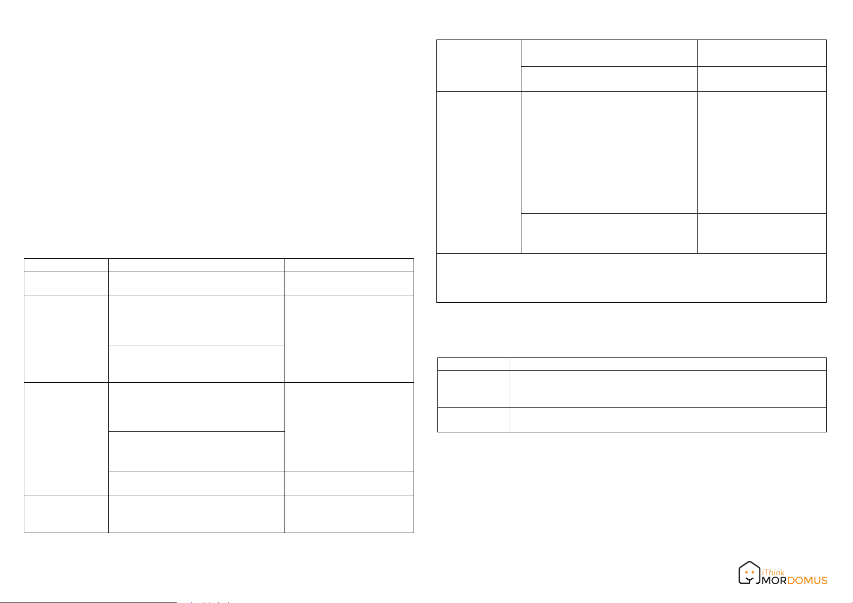
Function Description LED Indication
No node ID The Z-Wave Controller does not allocate
a node ID to the meter. LED 2-second on, 2-second
off
Inclusion 1. Put your Z-Wave controller into
inclusion mode by following the
instructions provided by the controller
manufacturer.
One press one flash LED
2. Pressing Include button three times
within 2 seconds will enter inclusion
mode.
Exclusion 1. Put your Z-Wave controller into
exclusion mode by following the
instructions provided by the controller
manufacturer.
One press one flash LED
2. Pressing Include button three times
within 2 seconds will enter exclusion
mode.
3. Node ID has been excluded. LED 0.5s On, 0.5s Off
(Enter auto inclusion)
Reset 1. Pressing INCLUDE_BUTTON three
times within 2 seconds will enter
inclusion mode.
Use this procedure only in
the event that the primary
controller is lost or otherwise
2. Within 1 second, press Include
button again for 5 seconds. inoperable.
3. IDs are excluded. LED 0.5s On, 0.5s Off
(Enter auto inclusion)
Association 1.
The iZ2EM is an always listening Z-
Wave device, so associations be
added or removed by a controller at
any time.
Or If your controller requires to have
the iZ2EM send a 'node information
frame' or NIF for associations,
pressing the On/Off button three times
within 2 seconds will cause the iZ2EM
to send its NIF.
LED One press one flash
2. There are 3 groups for the meter

Adding a node ID allocated by Z-Wave Controller means inclusion. Removing a node
ID allocated by Z-Wave Controller means exclusion.
Failed or success in including/excluding the node ID can be viewed from the Z-Wave
Controller.
LED Indication
To distinguish what mode the meter is in, view from the LED for identification.
State Type
No node ID
Learning
LED Indication
Under normal operation, when the meter has not been allocated a
node ID, the LED flashes on and off alternately at 2 seconds
intervals.
When iZ2EM is in learning mode, LED flashes on and off alternately
and repeatedly at 0.5 second intervals.
Choosing a Suitable Location
1.
Do not locate the meter facing direct sunlight, humid or dusty place.
2.
The suitable ambient temperature for the Switch is 0°C~40°C.
3.
Do not locate the meter where exists combustible substances or any source of
heat, e.g. fires, radiators, boiler etc.
4.
After putting it into use, the body of meter will become a little bit hot of which
phenomenon is normal.
www.mordomus.com
Installation
1.
Put the meter into a wall box and connect the AC power wire L,N to iZ2EM
connector L, N.
2. The black wire of current sensor, CT1 or CT2, should connected to the negative
terminal of iZ2EM,CT1- or CT2-. Another wire should connected to the plus
terminal of iZ2EM,CT1+ or CT1+.
3. There is a clasp on the side of the current sensor, it can lock or unlock the clamp.
It is convenient to circle the already connected cable.
Troubleshooting
Cause of Failure RecommendationSymptom
The meter is not working
and LED off 1. The meter is not
connect to the Main
power
2. The meter break down
1. Check power connections
2. Don’t open up the meter and send it
for repair.
The meter cannot report to
the group 1. Not carry out
association
2. Same frequency
interference
1. Carry out association
2. Wait for a while to re-try
Specification
Operating Voltage
Rated Primary Current
Range
Operating Temperature
Frequency Range
100~240VAC
0.05A~60A x 2 Channel ; Split Core Transformer
Minimum 40 m in door 100m outdoor line of sight
0°C ~ 40°C
iZ2EM-1 868.40 & 869.85MHz (EU) /
iZ2EM-2 908.40 & 916.0MHz(USA/Canada) /
iZ2EM-3 922~927MHz (Taiwan/JP)
** Specifications are subject to change and improvement without notice.
DANGER
Danger of electrocution!
All works on the device may be performed only by a qualified and licensed electrician.
Observe national regulations.
Any works introducing changes into the configuration must be always performed with
disconnected voltage.
www.mordomus.com
1. Do not locate the Module facing direct sunlight, humid or dusty place.
2. The suitable ambient temperature for the Module is 0°C~40°C.
3. Do not locate the Module where exists combustible substances or any source of
heat, e.g. fires, radiators, boiler etc.
4. After putting it into use, the body of Module will become a little bit hot of which
phenomenon is normal.
Warning:
1.Plug out to disconnect from power supply; Do not plug in line.
2. Do not exceed the max rating.
Disposal
This marking indicates that this product should not be disposed with
other household wastes throughout the EU. To prevent possible harm to
the environment or human health from uncontrolled waste disposal,
recycle it responsibly to promote the sustainable reuse of material
resources. To return your used device, please use the return and
collection systems or contact the retailer where the product was
purchased. They can take this product for environmental safe recycling.
Choosing a Suitable Location
However, there is no guarantee that interference will not occur in a particular
installation.
If this equipment does cause harmful interference to radio or television reception,
which
can be determined by turning the equipment off and on, the user is encouraged to try
to correct the interference by one of the following measures:
•Reorient or relocate the receiving antenna.
•Increase the separation between the equipment and receiver.
•Connect the equipment into an outlet on a circuit different from that to which the
receiver is connected.
•Consult the dealer or an experienced radio/TV technician for help.
This device complies with Part 15 of the FCC Rules. Operation is subject
to the following two conditions:
(1) This device may not cause harmful interference, and
FCC Interference Statement
This equipment has been tested and found to comply with the limits for a Class B
digital device, pursuant to Part 15 of the FCC Rules.
These limits are designed to provide reasonable protection against harmful
interference in a residential installation.
This equipment generates, uses and can radiate radio frequency energy and, if not
installed and used in accordance with the instructions, may cause harmful
interference to radio communications.
(2) This device must accept any interference received, including interference that
may cause undesired operation.
FCC Caution: Any changes or modifications not expressly approved by the party
responsible for compliance could void the user's authority to operate this equipment.
This transmitter must not be co-located or operating in conjunction with any other
antenna or transmitter.
www.mordomus.com

Popular Measuring Instrument manuals by other brands

GOK BC-1 Series Assembly and operating manual

GOK

GOK BC-1 Series Assembly and operating manual

Siemens 9810 Series user manual

Siemens

Siemens 9810 Series user manual

Flonidan G4SZV user manual

Flonidan

Flonidan G4SZV user manual

TIMEDOX Silver quick start guide

TIMEDOX

TIMEDOX Silver quick start guide

Chauvin Arnoux C.A 6292 manual

Chauvin Arnoux

Chauvin Arnoux C.A 6292 manual

Hanna Instruments HI9064 instruction manual

Hanna Instruments

Hanna Instruments HI9064 instruction manual

YOKOGAWA VY Series user manual

YOKOGAWA

YOKOGAWA VY Series user manual

engelmann microCLIMA DE-16-MI004-PTB025 Installation and operating instructions

engelmann

engelmann microCLIMA DE-16-MI004-PTB025 Installation and operating instructions

Stoneridge SE5000 user manual

Stoneridge

Stoneridge SE5000 user manual

Ditel MICRA-E Quick installation guide

Ditel

Ditel MICRA-E Quick installation guide

Trans instruments Marine Salt Testa Operation manual

Trans instruments

Trans instruments Marine Salt Testa Operation manual

ST N30U user manual

ST

ST N30U user manual

Precision Medical 1MFA3001 user manual

Precision Medical

Precision Medical 1MFA3001 user manual

Fema M60-C1 user manual

Fema

Fema M60-C1 user manual

Heathkit V-4 user manual

Heathkit

Heathkit V-4 user manual

Acom H3-VR Supplementary manual

Acom

Acom H3-VR Supplementary manual

YOKOGAWA EXAxt ZR22G Technical note

YOKOGAWA

YOKOGAWA EXAxt ZR22G Technical note

Seitron BE COOL V1 SMART quick guide

Seitron

Seitron BE COOL V1 SMART quick guide

manuals.online logo
manuals.online logoBrands
  • About & Mission
  • Contact us
  • Privacy Policy
  • Terms and Conditions

Copyright 2025 Manuals.Online. All Rights Reserved.