Smart Tweezers Colibri St5S User manual
3

TABLE OF CONTENTS
Notice 1
Warranty 1
Safety Precautions 2
Getting Started 3
Overview 3
How it works 4
Controls 5
Power On 6
Display 6
Displayed Parameters 7
Menu Structures And Functions 8
Measurement menu 12
Setting Menu 14
Measurement Features 19
Maintenance 21
22
23
Appendix B. Default Settings 25
25
-

1
NOTICE:TO THEBEST OF OURKNOWLEDGETHIS DOCUMENTIS BELIEVEDTOBE ACCURATE.THE MANUFACTURER RESERVESTHE RIGHTTO
CHANGETHE INFORMATION AND DOES NOT ASSUMEANYRESPONSIBILITY FOR OMISSIONSAND/OR ERRORSFOUNDINTHISDOCUMENT.
WARRANT Y: MANUFACTURER WARRANTS THIS PRODUCT TO BE FREE FROM DEFECTS IN MATERIALS AND WORKMANSHIP
FOR A PERIOD OF ONE (1)YEAR FROM THE SHIPMENT DATE. MANUFACTURER WARRANTS THE FOLLOWING ITEMS FOR
NINETY (90)DAYS FROM THE DATE OF SHIPMENT: RECHARGEABLE BATTERIES, DISKS AND DOCUMENTATION. DURING THE
WARRANTY PERIOD,THEMANUFACTURER WILL, AT ITSDISCRETION,EITHER REPAIRORREPLACE ANYPRODUCT THATPROVES
TO BE DEFECTIVE. TO EXERCISE THIS WARRANTY, WRITE OR CALL YOUR LOCAL DISTRIBUTOR. YOU WILL BE GIVEN PROMPT
ASSISTANCE ANDRETURNINSTRUCTIONS.PLEASE SENDTHE PRODUCTWITHSHIPPINGPREPAID TO THEINDICATEDSERVICE
FACILITY. REPAIRS WILL BE MADE AND THE PRODUCT WILL BE RETURNED TO YOU. REPAIRED OR REPLACED PRODUCTS ARE
WARRANTED FOR THEBALANCEOFTHE ORIGINALWARRANTY PERIOD,ORNINETY (90)DAYSFROM THEDATE OF THEREPAIR.
THIS WARRANT Y DOES NOT COVER THE REPAIR OF ANY PRODUCT WHOSE SERIAL NUMBER HAS BEEN ALTERED, DEFACED OR
REMOVED. THISWARRANTY DOES NOTCOVER FINISHES (SCRATCHES ON SURFACEORSCREEN),NORMALWEARANDTEAR, NOR
DOES IT COVERDAMAGERESULTINGFROM MISUSE,DIRT,LIQUIDS,PROXIMITYOREXPOSUREOFHEAT,ACCIDENT, ABUSE,NEGLECT,
MISAPPLICATION, OPERATION OUTSIDE OF THEENVIRONMENTALSPECIFICATIONS, TAMPERING, UNREASONABLEUSE,SERVICE
PERFORMEDORATTEMPTEDBY UNAUTHORIZEDSERVICE CENTERS, FAILURE TOPROVIDEREASONABLEAND NECESSARY MAINTENANCE.
THIS WARRANTY DOES NOT APPLY TO DEFECTS RESULTING FROM PRODUCT MODIFICATION WITHOUT MANUFACTURER’S
EXPRESS WRITTEN CONSENT, OR MISUSE OF ANY PRODUCT OR PART. THIS WARRANTY ALSO DOES NOT APPLY
TO SOFTWARE, NON-RECHARGEABLE BATTERIES, DAMAGE FROM BATTERY LEAKAGE, AND IMPROPER POLARITY
OF THE BATTERIES OR PROBLEMS ARISING FROM NORMAL WEAR OR FAILURE TO FOLLOW INSTRUCTIONS. THIS
WARRANTY DOES NOT COVER LCD DAMAGE, PHYSICAL DAMAGE TO THE JOG DIAL BUTTON, SLIDE SWITCH AND
RESET SWITCH; ELECTRICAL DAMAGE OF THE PRODUCT DUE TO HIGH VOLTAGE OR IMPROPER BATTERY TYPE.
THEDESIGNANDIMPLEMENTATIONOFANY CIRCUIT BASEDONTHISPRODUCT ISTHE SOLE RESPONSIBILITY OF THECUSTOMER.
MANUFACTURERDOESNOT WARRANTANY DAMAGE THATOCCURS AS ARESULT OF THEUSER’SCIRCUITORANY DEFECTS THAT
RESULT FROM USER-SUPPLIED PRODUCTS. THIS WARRANTYDOESNOT APPLYTO REPAIRSORREPLACEMENTS NECESSITATED
BY ANY CAUSE BEYOND THECONTROLOFFACTORYINCLUDING,BUT NOT LIMITED TO,OPERATION CONTRARY TOFURNISHED
INSTRUCTIONS, SHIPPING ACCIDENTS, MODIFICATIONORREPAIRBY THEUSER,NEGLECT, ACCIDENTS OR OTHER ACTSOFGOD.
THEFOREGOINGISINLIEU OF ALL OTHER EXPRESSEDWARRANTIESAND THE MANUFACTURERDOESNOT ASSUME OR AUTHORIZE
ANYPARTYTO ASSUME FORITANY OBLIGATIONORLIABILITY. THE DURATION OF ANYWARRANTIESTHATMAY BE IMPLIEDBY LAW
(INCLUDINGTHE WARRANTIESOFMERCHANTABILITY AND FITNESS)ISLIMITEDTO THE TERMOFTHISWARRANTY.INNOEVENT
SHALL THEMANUFACTURER BE LIABLE FORSPECIAL, INCIDENTAL OR CONSEQUENTIAL DAMAGES ARISING FROMOWNERSHIP OR
USE OF THIS PRODUCT,ORFOR ANY DELAYINTHE PERFORMANCEOFITS OBLIGATIONS UNDER THIS WARRANTYDUE TOCAUSES
BEYOND ITS CONTROL. THIS WARR ANT Y IS LIMITED IN DURATION TO ONE (1)YE AR FROM THE DATE OF ORIGINAL PURCHASE.
THIS WARRANTY IS IN LIEU OF ALL OTHER WARRANTIES, EXPRESSED OR IMPLIED, INCLUDING ANY IMPLIED WARRANTY OF
MERCHANTABILITY OR FITNESSFOR APARTICULAR USE.THE REMEDIESPROVIDEDHEREIN AREBUYER’S SOLE ANDEXCLUSIVE
REMEDIES. NEITHER MANUFACTURER,NOR ANY OF ITSEMPLOYEESSHALLBE LIABLEFOR ANY DIRECT,INDIRECT,SPECIAL, INCIDENTAL
OR CONSEQUENTIAL DAMAGES ARISING OUTOFTHE USE OF ITS DEVICES ANDSOFTWARE EVEN IF MANUFACTURERHAS BEEN
ADVISEDINADVANCEOFTHE POSSIBILITYOFSUCH DAMAGES.SUCH EXCLUDEDDAMAGES SHALL INCLUDE,BUT ARE NOTLIMITEDTO:
COSTS OF REMOVAL AND INSTALLATION, LOSSES SUSTAINED AS THERESULTOF INJURYTOANYPERSON,OR DAMAGE TO PROPERTY.

2
The following safety precautions should be observed prior to using
this product and any associated accessories. Although devices and
accessories would normally be used with non-hazardous voltages,
there are situations where hazardous conditions may be present.
recognize shock hazards and are familiar with the safety precautions
required to avoid possible injury. Read and follow all installation,
operation, and maintenance instructions carefully before g the
protection provided by the product may be impaired.
Inspect the Smart Tweezers case before using.
Do not use the device if it appears to be damaged.
• Do not use the device if it operates abnormally.
• Do not attempt to measure any components in-
circuit when your circuit is alive or active.
To avoid possible damage to Smart Tweezers or to the
• Disconnect circuit power supply and discharge all high-voltage
capacitors before testing resistance, inductance, or capacitance.
• Do not apply external voltages of more than 1.6 V.
• Use proper terminals and functions for your measurements.
• Only supplied charger (DC 5V) should be used to charge the battery.
The WARNING heading in this manual indicates
dangers that might result in personal injury or death.
Always read the associated information very carefully
before performing the indicated procedure.
The CAUTION heading in the manual indicates hazards that could
damage the device. Such damage may invalidate the warranty.

3
This section summarizes basic operation of Smart Tweezers.
In the section:
Overview of the device controls.
Describes the power-on and power-off sequence,
the warm-up time, and default conditions.
Discusses the display format and messages that
may appear while using the device.
Covers menu structure, system
settings and features.
Smart Tweezers (ST) is a portable impedance measuring
device. ST is capable of measuring resistance, capacitance
or inductance over a range of more than 8 orders of
magnitude. The device has a basic accuracy better than
0.2% (resistance) and operates at four test frequencies.
Smart Tweezers is controlled by a microcontroller that sets
measurement conditions, processes data and operates the display
and user interface. The device has a unique mechanical design that
allows manipulation SMT components with size down to 0201.
In actual use Smart Tweezers provides more accurate results than
most of the benchtop LCR meters due to small and very predictable
parasitics of its probes. Probability of measurement errors
associated with setup (wires, tips, probes and etc.) is minimal.

4
ST evaluates impedance of a component by measuring the voltage
across the component and current through it. The complex ratio
of voltage to current is equal to the complex impedance. The unit’s
processor calculates various parameters that are displayed i.e. R, C or L.
Voltage across the component is generated by the test signal
source Vs. Both the amplitude and frequency of Vs can be set. The
voltage is applied to the device under test (DUT) through the source
output of AI provides a signal proportional to the current, I*Ri.
Voltage across the DUT is measured by a separate signal path
Voltage and current signals are processed by the A/D converter.
Obtained values are then corrected using calibration factors,
converted to impedance and sent to the display.
There are four selectable frequencies: 100Hz, 120Hz,
1.0kHz and 10kHz. The output frequency is accurate
to 50 ppm (0.005%). Frequencies are set in the menu
or by moving the Navigation Control UP.
There are two output voltage levels that can be selected: 0.5 Vrms
and 1.0 Vrms. The accuracy of the output voltage levels is 2 %.
The output voltage is applied to the device under test through the
source impedance. The voltage across the device is always less than
DUT AU
RS
VS
VOLTAGE SIGNAL
TO ADC
CURRENT SIGNAL
TO ADC
AL
RI

as Z5U ceramic capacitors (test voltage = 0.5 Vrms
for 25V parts and 1.0V for < 16V parts).
Note: Use the largest voltage possible for the best SNR and accuracy.
The Navigation Control
The navigation switch is used to select a function or to change a
setting of Smart Tweezers. The navigation switch can be moved
(rocked) in 4 directions (UP, DOWN, LEFT, RIGHT). Selection
is performed by pressing along the vertical axis (PRESS).
Quick Controls
The Quick Controls allow changing test parameters or modes
without entering the general menu by moving the Navigation
Control UP, DOWN, LEFT and RIGHT as shown below.
5
To avoid errors do
not use the Quick Controls
during component
measurement.
UP
DOWN
LEFT/RIGHT
10 kHz
1 kHz
100 kHz
120 kHz
AUTO
R
L
C
(Z)
ESR
DIODE
DCR
AUTO
0.5 V
1.0 V

6
To turn the Smart Tweezers ON,
press the navigation switch twice.
Note: Once powered on, the unit will perform
the last selected function.
- ST powers off automatically if neither a
measurement is performed nor the navigation control is
operated for approximately 30 seconds (default value).
The power off timeout value can be set by changing
the TIMEOUT setting in the SYSTEM menu.
The default power-off timeout is 30 seconds in a
measurement mode and 30 seconds in the MENU mode.
Note: Automatic power-off does not occur if test
frequency is manually set to 10kHz.
The screen is divided in four areas:
– change test ranges
DOWN – change test signal levels
LEFT/ – change measurement modes
• Primary Display
• Secondary Display
• Test Parameters
• Device Status with
Test Mode Indicator
PRIMARY DISPLAY
SECONDARY DISPLAY
TEST MODE BATTERY INDICATOR

7
The Primary Display is located in the middle
of the screen and uses the largest font. It shows the dominant
impedance parameter reading typically with 5 digits displayed.
The Secondary Display is located just above the
Primary Display. It shows the minor impedance parameter reading.
The Test Parameters area is at the top of the
screen and provides information about current test conditions
such as Test Frequency, Range, Test Signal level, Test Model.
The Device Status area is at the bottom of the
screen and provides information about the current Test Mode
and settings of the device: Hold, Audio and Battery Status.
The Test Mode Indicator sign is
located immediately to the left of the Primary Display.
Symbols A, R, L, C, |Z|, ESR and Diode indicate Auto,
Resistance, Inductance, Capacitance, Impedance and ESR
measurement and Diode Test mode respectively.
The measurement mode setting (R, L+R, C+R, C+D, L+Q,
|Z|, ESR and AUTO) determines the measurement
type and the displayed parameters
Resistance is shown on the Primary The resistance
displayed is either the equivalent series or parallel resistance
Inductance is shown on the Primary Display and the series
resistance on the Secondary Display. The units of inductance are µH,
mH or H. Resistance is the real part of the impedance. Resistance
Inductance is shown on the Primary Display and
the quality factor Q on the Secondary Display. Inductance
units are µH, mH or H. Q is the ratio of the imaginary part of the
impedance to the real part of the impedance. Q is dimensionless
and the same for both series and parallel representations. A
good inductance has a large L and a small R and thus a high Q..

8
Capacitance is shown on the Primary Display and the
parallel resistance R, is shown on the Secondary Display. The units
(C < 500 pF) or serial (C > 500 pF) equivalent circuit diagram is used.
Capacitance is shown on the Primary Display and
dissipation factor D on the Secondary Display. The capacitance
is either the equivalent series or parallel capacitance of the
ratio of the real part of the impedance to the imaginary part
of the impedance, or 1/Q. D is dimensionless and the same
for series and parallel representations. A good capacitor has
a large C (imaginary) and a small R (real) and thus a low D.
The Impedance of the component is shown
The equivalent series resistance of the capacitor is
ST determines which component model is the most
accurate representation of the DUT and automatically selects the
appropriate parameter set. The determination is made as follows:
• For |Q| < 0.15 the R mode is selected.
• For Q > +0.15 the L+R or L+Q mode is selected (depends on user settings).
• For Q < -0.15 the C+R or C+D mode is selected.
• For C < 500 pF Parallel circuit diagram (Rp) is used.
• For C >= 500 pF Serial circuit diagram (Rs) is used.
This section describes menu structure and device parameters
setting. Smart Tweezers menu system contains
• Main menu — main menu items
• System menu — system menu items
• Sound menu – sound settings
• Display menu — display settings

9
• Service menu — service functions
• Measurement menu – measurement functions and settings
• Mode menu – measurement modes
• Setting menu – measurement parameters settings
Move the Navigation Control UP or DOWN to move cursor
to the desired menu item and PRESS it to select the item.
The Current Setting cursor indicates the current setting.
Main menu is used to access System menu, Measurement menu or to
restore measurement parameters to the default state using Autoset.
• Select AUTOSET to reset parameters to the default settings.
• Select SYSTEM to change user interface and operation parameters.
• Select MEASURE to specify measurement settings.
10
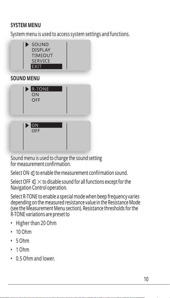
System menu is used to access system settings and functions.
Sound menu is used to change the sound setting
Select ON
Select OFF to disable sound for all functions except for the
Navigation Control operation.
Select R-TONE to enable a special mode when beep frequency varies
depending on the measured resistance value in the Resistance Mode
(see the Measurement Menu section). Resistance thresholds for the
R-TONE variations are preset to
• Higher than 20 Ohm
• 10 Ohm
• 5 Ohm
• 1 Ohm
• 0.5 Ohm and lower.

11
The mode could be used for locating shorted part of a circuit e.g. on a PCB.
Display menu is used to change display’s settings
• Select RIGHT to set the “Right Handed” display mode
• Select LEFT to set the “Left Handed” display mode
Select CONTR to adjust display contrast. Move Navigation
Control UP or DOWN to change contrast. PRESS to
exit menu at the adjusted contrast level.
Select TIMEOUT to adjust the timeout before the unit goes to
sleep mode. Move Navigation Control UP or DOWN to change
the timeout value (10sec – 200sec) PRESS to exit the menu..

12
Select BATTERY to measure the actual battery voltage. PRESS to exit
Select S/N to display the device Serial Number
Measurement modes and settings
The Mode menu is used to set the measurement mode. Select RES,
IND, CAP, IMP or ESR menu items to measure desirable component or
parameter as Resistance, Inductance, Capacitance, Impedance and
ESR accordingly. For automatic measurement select AUTO (default).

13
Select AUTO mode (AM sign appears at the
left bottom corner of display) for automatic measurement
of inductance, capacitance or resistance.
Note: In the AUTO mode ST uses 1kHz test frequency by
default and has a limited sensitivity. Automatic detection
may not work for small value capacitors and inductors.
In this case 10kHz test frequency must be used..
Enables Resistance measurement mode.
See section MEASUREMENT FEATURES for more information.
Enables Capacitance measurement mode.
See section MEASUREMENT FEATURES for more information.
Enables Capacitance measurement mode.
See section MEASUREMENT FEATURES for more information.
Enables the Impedance measurement mode.
See section MEA SUREMENT FE ATURES for more information.
Enables the ESR measurement mode. See section
MEASUREMENT FEATURES for more information.
Enables diode test mode showing
diode polarity or SHORT indicating a faulty diode
Verify that 1.0 Vrms test signal level is set to test diodes.
Enables DCR resistance measurement mode.
The DCR measurement measures the resistance of an
unknown component by applying DC voltage.
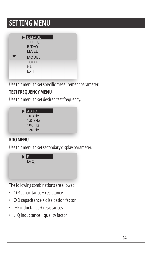
14
Use this menu to set desired test frequency.
Use this menu to set secondary display parameter.
The following combinations are allowed:
• C+R c apaci t an ce + resistance
• C+D c apaci t an ce + dissipat ion f actor
• L+R induc t an ce + resi s tances
• L+Q induc tance + qualit y fac tor

15
Use this menu to set desirable test signal level.
Default value is 0.5 Vrms.
1.0 Vrms is equal to 2.8 Vp-p
Any non-ideal component can be represented as a resistive
component in series or in parallel with a reactive component.
Depending upon the characteristics of the component the series or
parallel model will be more accurate. In most cases, parts are best
approximated by the series model. Manufacturers often specify
which representation should be used when testing their devices.
The LCR meter can display Automatic (A) Parallel ( S ) or Series ( P )
model data. Use this menu to choose the parallel and series model.
Series model is set as the default setting
This function is designed for component sorting. It checks whether the
measured component is within preset tolerance from the reference
component. The tolerance ranges available are 1%, 5%, 10%, and 20%.

16
To preset a tolerance range:
• Select manual L, C or R measurement mode (see MODE menu)
• Enable the HOLD mode (see HOLD menu)
• Connect to an appropriate component selected as a reference value
• Enter the TOLERance menu and select desired tolerance range
Smart Tweezers will display difference in percent from
the reference value and the beeper will beep
• 1 time when the component is within the setting tolerance.
• 3 times whenever the component under
test exceeds the setting tolerance.
To reset the tolerance mode select AUTOSET from the
main menu or DEFAULT from the settings menu.
Allows storing of measurement offsets to
perform relative measurements (NULL).
When relative measurements are performed, also called
null, each reading is the difference between a stored
(measured) relative value or offset and the input signal.
One common application is to increase the accuracy
of a small resistance measurement by storing (nulling)
the test lead resistance (test leads shorted).
Obtaining the leads offset (nulling) is also particularly important
prior to making small capacitance measurements (test leads open).
Smart Tweezers allows to store measurement
offset for L, C, R component separately.

17
To store an offset
• Select manual L, C or R measurement mode (see MODE menu)
• Enable the HOLD mode (see HOLD menu)
• Obtain offset value by measuring a component or
by nulling test leads (see examples below)
• Enter the NULL menu and select SET
Nulling test leads for small resistance measurement
• Select manual R measurement mode (see MODE menu)
• Enable the HOLD mode (see HOLD menu)
• Short tweezers leads to obtain offset value
• Enter the NULL menu and select SET
Nulling test leads for small capacitance measurement
•
test frequency (see SETTINGS menu)
• Enable the HOLD mode (see HOLD menu)
• Bring tweezers leads to the distance equal to
the size of the component to measure (e.g. 0.5
mm) to obtain capacitance offset value
• Enter the NULL menu and select SET
During measurements an asterisk will appear beside the test mode indicator
for which the offset has been stored indicating relative measurement.

18
To reset (set to zero) the stored offset for a particular test mode
• Select manual L, C or R measurement mode (see MODE menu)
• Enable the HOLD mode (see HOLD menu)
• Enter the NULL menu and select ZERO
To reset the NULL mode completely select AUTOSET from
the main menu or DEFAULT from the SETTINGS menu.
Allows to hold last reading on display.
Period menu is used to set the time period between measurements.
This setting does not affect measurement accuracy.
Default setting is 1sec.
Note: Short period may reduce the battery life.
Other manuals for Colibri St5S
1
Table of contents
Other Smart Tweezers Measuring Instrument manuals


Popular Measuring Instrument manuals by other brands


sauermann
sauermann E INSTRUMENTS E6000 operating & maintenance manual

Stanford Research Systems
Stanford Research Systems SR785 Brochure & specs

Pfeiffer Vacuum
Pfeiffer Vacuum QMG 422 operating instructions

PULOX
PULOX PO-230 instruction manual

Mirion Technologies
Mirion Technologies RDS-31 S user manual

Entes
Entes MPR-3 Series user manual


