Aeroqual Dust Sentry Pro User manual

MRK-D-0048 V4 Aeroqual Dust Sentry / AQS User Guide Page | 2
User Guide Revision History
Date
Revision number
Description of change
Affected Sections
June 2017
1.0
First release
-
September 2017
2.0
NO2 and VOC added
1, 1.1
May 2018
3.0
Calibration section updated
5.0
February 2019
4.0
Combining AQS, Dust
Sentry, Dust Sentry Profiler
All
Alternative sources of information and help
In addition to this user guide, Aeroqual offers other sources of information which can assist in the
operation of the monitors. The Aeroqual website contains brochures, technical notes and user guides
for all products.
www.aeroqual.com
Aeroqual’s training website contains a comprehensive document library of technical notes and service
and calibration templates to download and print. The training website has detailed descriptions of
service activities and calibration and installation examples and is updated regularly. Video tutorials
are featured heavily.
www.training.aeroqual.com
For technical support, contact the Aeroqual distributor in your local country. If local technical support
is not available contact the Aeroqual support team: technical@aeroqual.com.
Where possible, references to further material will be provided throughout this document
Online reference
training.aeroqual.com
Online video
YouTube Channel: Aeroqual Service and Maintenance playlist

MRK-D-0048 V4 Aeroqual Dust Sentry / AQS User Guide Page | 3
Table of Contents
1Dust Sentry / Dust Sentry Pro / AQS 1 Introduction........................................................................5
1.1 Overview .................................................................................................................................5
1.2 Product comparison ................................................................................................................6
1.3 Applications by product...........................................................................................................6
1.4 Optional external sensors .......................................................................................................7
1.5 Dimensions..............................................................................................................................7
1.6 Specifications..........................................................................................................................8
2Quick Setup Guide...........................................................................................................................9
2.2 Pre-planning..........................................................................................................................11
2.3 Unpacking .............................................................................................................................11
2.4 Assembly...............................................................................................................................12
2.5 Power Requirements.............................................................................................................15
2.6 Wiring auxiliary sensors ........................................................................................................16
3Mounting and Site Positioning Guidelines.....................................................................................18
3.1 Mounting................................................................................................................................18
3.2 Inlet height.............................................................................................................................18
3.3 Measurement Interference....................................................................................................18
3.4 Safety....................................................................................................................................19
4Connectivity ...................................................................................................................................20
4.1 Aeroqual Connect (via Direct WIFI / LAN) ............................................................................20
4.2 Aeroqual Cloud (via Network WIFI / Modem) .......................................................................21
4.3 Communication settings........................................................................................................25
4.4 Resetting the communication settings back to factory settings ............................................26
5Operation .......................................................................................................................................27
5.1 Manage Data.........................................................................................................................27
5.2 Calibration and Service.........................................................................................................29
5.3 Configure Instrument.............................................................................................................29
5.4 Diagnostics and Advanced....................................................................................................30
5.5 Administration........................................................................................................................31
6Service & Maintenance..................................................................................................................32
6.1 Service frequency guidelines ................................................................................................32
6.2 Flow meters and flow measurement.....................................................................................33
6.3Manual Service Mode ...........................................................................................................33
6.4 Journal...................................................................................................................................34
6.5 Maintenance procedures.......................................................................................................34
6.6 Factory calibration of Particle Monitor...................................................................................46
6.7 Scheduled maintenance........................................................................................................47
7Calibration......................................................................................................................................48
7.1 Gas module calibration .........................................................................................................48
7.2 Particle Monitor calibration....................................................................................................57

MRK-D-0048 V4 Aeroqual Dust Sentry / AQS User Guide Page | 4
8Troubleshooting .............................................................................................................................60
9Copyright........................................................................................................................................62
10 Compliance ...............................................................................................................................62
11 Warranty....................................................................................................................................62
12 Appendix ...................................................................................................................................63
12.1 Gas module design ...............................................................................................................63
12.2 Particulate Matter module design..........................................................................................65
12.3 Mains wiring color guide........................................................................................................67
12.5 Calibration Records...............................................................................................................68
MRK-D-0048 V4 Aeroqual Dust Sentry / AQS User Guide Page | 5
1 Dust Sentry / Dust Sentry Pro / AQS 1 Introduction
1.1 Overview
Dust Sentry / Dust Sentry Pro / AQS 1 (collectively referred to herein as ‘monitors’) are tools for air
quality professionals to target specific applications of interest in industrial, urban environment and
regulatory applications. It is a flexible air quality monitoring system that can be configured for a range
of uses.
Key technology features of the monitors enable them to deliver data with very strong correlation to
EPA-approved monitors –‘Near Reference’–over extended periods of time; several years with
appropriate maintenance.
Housed in a rugged, lockable weatherproof (IP 65) enclosure, the monitors include an embedded PC
and full software system for remote technical support, data management and analytics.
Users can make use of the embedded PC running proprietary Aeroqual Connect software, or
optional web-based Aeroqual Cloud software for data storage and management of networks of
monitors.
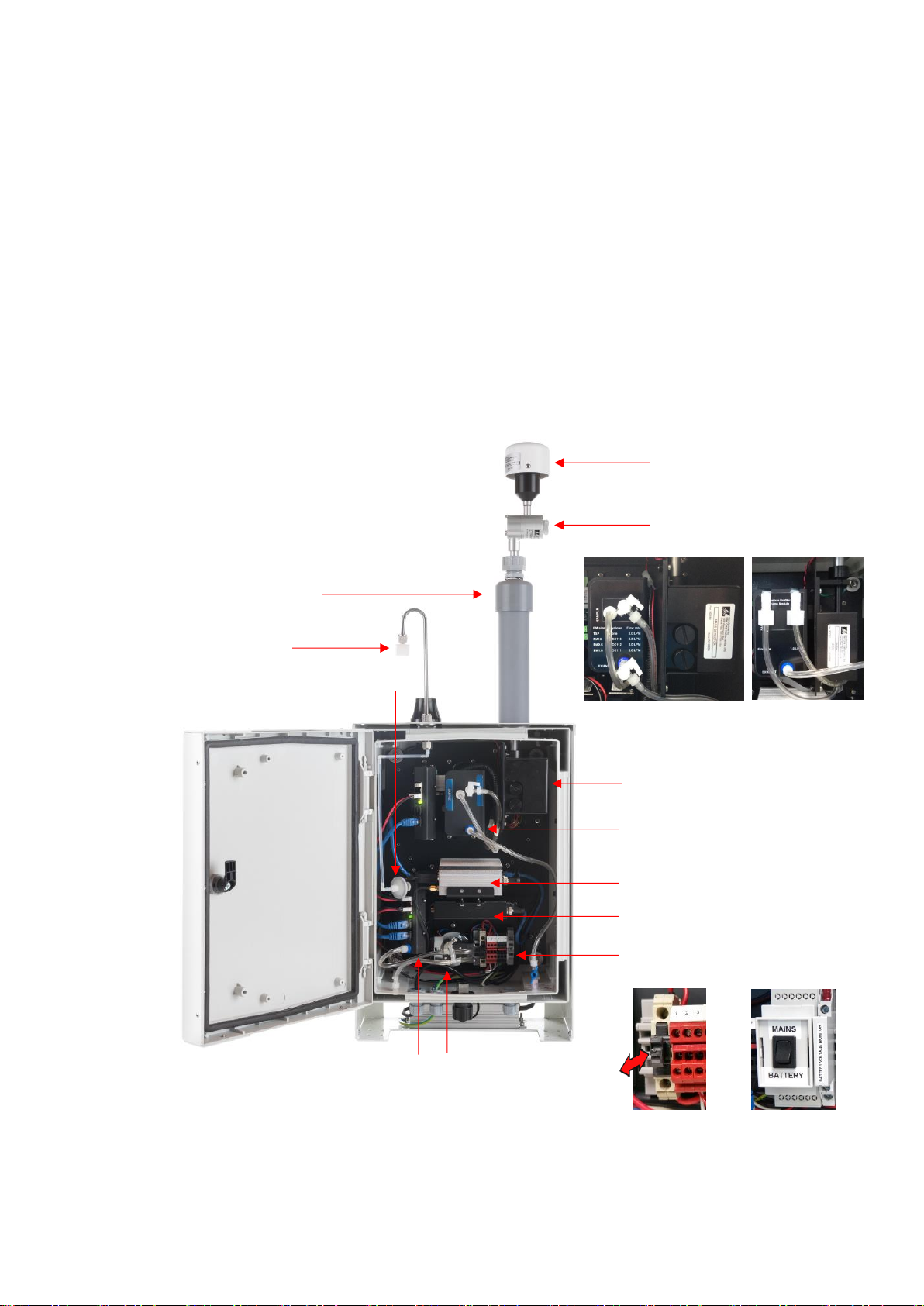
Figure 1-1 Key components
Gas sampling inlet
(AQS only)
TSP inlet
Sharp cut cyclone
(PM10 or PM2.5 or PM1)
Particle sampling inlet
Particle sampling pump
Particle monitoring engine
(Nephelometer or OPC)
See section 12.2
Embedded computer
12V DC power rail and fuse
Gas sampling module
(AQS only)
Gas sampling pump
(AQS only)
Modem (Optional)
Inlet filter on gas sampling line
(AQS only)
Fuse and On
/ Off switch
Mains / Solar or
Battery switch
(Optional)
Particle Monitor
Nephelometer)
Particle Profiler
(Optical Particle
Counter (OPC))

MRK-D-0048 V4 Aeroqual Dust Sentry / AQS User Guide Page | 6
1.2 Product comparison
Dust Sentry and Dust Sentry Pro both measure particulate concentrations using laser light scattering
but the methodology and optics design are different, this means that the Dust Sentry measures a single
size fraction selected by the user but the Dust Sentry Pro measures four size fractions simultaneously.
AQS 1 also measures gases in addition to particulate, up to three gas modules may be integrated.
Product
Particulate Measurement
Gas Measurement
Dust Sentry
TSP or PM10 or PM2.5 or PM1.0
None
Dust Sentry Pro
TSP and PM10 and PM2.5 and PM1.0 and 8 size counts
None
AQS 1
TSP or PM10 or PM2.5 or PM1.0
O3, NO2VOC
TSP and PM10 and PM2.5 and PM1.0 and 8 size counts
1.3 Applications by product
Applications for Dust Sentry
Designed for those who need to monitor and manage specific outdoor dust and particulate emissions
continuously and in real-time.
The Dust Sentry is a nephelometer-based monitor that delivers defensible and accurate mass
measurement for PM10, PM2.5, PM1, or TSP.
MCERTS certified and SCAQMD 1466 pre-approved.
For more detail see: https://www.aeroqual.com/product/dust-sentry-pm10-monitor
Applications for Dust Sentry Pro
Designed for those who need to monitor and manage multiple outdoor dust and particle size fractions
simultaneously and in real-time.
The Dust Sentry Pro delivers simultaneous measurement of PM10, PM2.5, PM1, TSP, and particulate
counts for 8 channels; 0.3, 0.5, 0.7, 1.0, 2.0, 3.0, 5.0, 10 microns.
For more detail see: https://www.aeroqual.com/product/dust-profiler-particle-counter
Applications for AQS 1
Designed for those who need to monitor and manage specific outdoor dust and particulates, and gases
continuously and in real-time.
The AQS 1 delivers affordable and defensible measurement of PM10,or PM2.5,or PM1, or TSP, and up
to three gases, all simultaneously.
MCERTS certified and SCAQMD 1466 pre-approved.
For more detail see: https://www.aeroqual.com/outdoor-air-quality/aqs-mini-air-quality-stations

MRK-D-0048 V4 Aeroqual Dust Sentry / AQS User Guide Page | 7
1.4 Optional external sensors
The monitors can integrate a number of external sensors such as weather sensors, solar radiation
and noise sensors. These sensors are mounted outside the monitor enclosure. The external sensors
below are available factory tested and ready to connect to the monitors.
MetOne MSO
weather station
Cirrus MK427
noise meter
Vaisala WXT536
weather station
Gill Instruments
Windsonic
Li-Cor LI-200
Pyranometer
See Section 2.6.1 for wiring external sensors.
1.5 Dimensions
These dimensions are for a visual representation only, for full details.–see section 1.6 Specifications.
Dimensions are in millimetres (mm).
.
330
187
483
360

MRK-D-0048 V4 Aeroqual Dust Sentry / AQS User Guide Page | 8
1.6 Specifications
Specifications are subject to change, please check www.aeroqual.com for the current specifications.
Dust Sentry
Dust Sentry Pro
AQS
Particulate
Measurement
Measurement technology
Near forward angle
laser scattering
nephelometer
Right angle laser
scattering particle
counter
Particle Counts
Range
Size channels
N/A
0-1,000,000 particles/L
0.3, 0.5, 0.7, 1.0, 2.0,
3.0, 5.0,10.0 µm
The AQS 1 can be
specified with either a
Near forward angle laser
scattering nephelometer
OR
Right angle laser
scattering particle
counter
Particulate
measurement
specifications will reflect
the measurement
technology chosen –see
panels to the left.
Particle Mass Measurement
PM1
PM2.5
PM10
TSP
Simultaneous?
Range / ug/m3
0 - 60000
0 - 60000
0 - 60000
0 - 60000
No –requires cyclone
Range / ug/m3
0 - 200
0 - 2000
0 - 5000
0 - 5000
Yes
Accuracy
<±(2 μg/m3+ 5 % of
reading)
<±(5 μg/m3+ 15 % of
reading)
Resolution
0.1 μg/m3
0.1 μg/m3
MCERTS certified
Yes
No
SCAQMD Rule 1466
Pre-approved
No
Auto zero check
Yes
No
Sample flow
2 LPM
1 LPM
Connect/ Cloud software
Yes
Yes
Factory calibration interval
24 months
12 months
Operating temperature
-10 °C to +50 °C
(14 °F to 122 °F)
-10 °C to +45 °C
(14 °F to 122 °F)
Heated inlet
Yes
Yes
Yes
Power consumption
24 W Max, depends upon configuration
Additional sensors
Weather station / Wind Speed and Direction / Noise / Solar incidence
Dimensions (H x W x D)
Weight
483 x 330 x 187 mm
(19 x 13 x 7.4 inches)
<13 kg
(28.6 lbs)
483 x 330 x 187 mm
(19 x 13 x 7.4 inches)
<13 kg
(28.6 lbs)
483 x 330 x 187 mm
(19 x 13 x 7.4 inches)
<15 kg
(33 lbs)
Gas Measurement
Ozone (GSS)
-
-
0 -500 ppb (0.1 ppb)
Nitrogen Dioxide (GSE)
-
-
0 -500 ppb (0.1 ppb)
Volatile Organic
Compounds (PID)
-
-
0 -500 ppb (0.1 ppb)
Gas calibration interval
-
-
As required
*Above 40 °C the laser may require more frequent servicing.
All monitors use the same software platform: https://www.aeroqual.com/product/air-monitoring-
software

MRK-D-0048 V4 Aeroqual Dust Sentry / AQS User Guide Page | 9
2 Quick Setup Guide
Before the monitor arrives (for full pre-planning details see section 2.2)
1. Visit the site and assess monitor location and suitability
Site will be representative of the pollutants you intend to measure.
Site is secure but with adequate access.
Site is appropriately open to all wind directions.
If you are planning a permanent deployment, check that there is nothing nearby
which could change and affect your project –like trees, planned buildings or new
roads and other potential interferences.
2. Ensure power is available on site
Ensure power is available Both Mains and Solar power can be used, but these
will need to be available and/or installed before the monitor arrives.
When installing power outlets (110 VAC to 230 VAC) for the monitor, they should
be weatherproof and installed safely.
Allow for 2 power outlets, one for the monitor and one for calibration equipment.
NOTE: A power lead with local plug will need to be supplied and wired to a connector
supplied with the monitor.
3. Install any additional infrastructure required for the installation
Mounting location and method has been identified. Most sites will require a way
of securely mounting the monitor. Pole Brackets (50.8 mm / 2 “304 Stainless U-
Bolt) are included to mount the monitor on a pole, anchored to the ground. Small
platforms have also been used successfully too.
If you have ordered Auxiliary sensors (Weather, noise etc.) you will need to
provide a means of mounting these also. You will need to supply a pole and
fixings to mount the sensor. Siting may be subject to local regulations.
Check you have the required tools.
4. Confirm communications specification (WIFI and/or cellular)
Check communications specifications and how the monitor software will be
accessed on site
For cellular access, purchase a dynamic IP network SIM card with at least 1 GB
data / month.
5. Plan for your time on site
When setting up for the first time allow at least four hours on site.
Allow for travel time to and from the site.
Confirm site operation times available for access.
Confirm personal protective equipment (PPE) that may be required on site.
6. Read the user guide
Familiarise yourself with the assembly steps.
Confirm the method of data access that will be supplied with the monitor (e.g.
Aeroqual Connect or Aeroqual Cloud).
Send any questions about things you are unsure about to
7. Write a checklist
Write your own checklist to ensure a smooth installation and setup.
Include any reporting requirements that will be required.

MRK-D-0048 V4 Aeroqual Dust Sentry / AQS User Guide Page | 10
After the monitor arrives
1. Unpack the monitor and inspect
Inspect the packaging and monitor for damage.
Check all items have been supplied
NOTE: A power lead with local plug will need to be supplied and
wired to a connector supplied with the monitor.
Section 2.3
2. Mount monitor
Mount the monitor to your platform or pole.
Attach the PM inlet.
Attach the gas inlet.
Open the door and check that all tubing, power and data
connections are secure.
Section 2
Section 2.4.1
Section 2.4.3
3. Power on the unit
Turn on the unit by pushing in the fuse.
Check that the Status LEDs on the modules, Embedded PC
and Modem (if fitted) are on and green.
Check that the sampling pump (PM only) or pumps (PM and
Gas) are running.
Section 2.5.4
4. Set up Wi-Fi / Modem and connect to the monitor
Connect to Aeroqual Connect
Connect to Aeroqual Cloud
Section 4.1
Section 4.2
5. Check sampling flow rates
Put the monitor into Service mode
Write a comment in the Journal that you are on site for
monitor commissioning.
Check the sampling system for leaks, rectify any leaks.
Check and adjust gas module flow rates to specification.
Check PM inlet flow rates and adjust if required.
Section 5.1
Section 6.4
Section 6.5.4
Section 6.5.4.2
Section 6.5.4.3
6. Attach optional auxiliary sensors
If you have purchased any auxiliary sensors (Weather,
Noise) mount these and run the cabling through the external
glands, and connect to the AUX module.
Section 2.6
7. Document setup in Journal
Note in the Journal that commissioning is complete.
Exit Service mode.
Section 6.4
Section 5.1
Installation and commissioning
Commissioning is the process of setting up a new monitor to work correctly on site. It is important that
the correct procedure for commissioning the monitors is followed to ensure reliable monitor operation
and to meet or exceed your data quality objectives. All monitors are supplied with a traceable factory
calibration. This calibration is applicable to the commissioning phase and accordingly Aeroqual does
not recommend an initial calibration as part of monitor commissioning.
Aeroqual provides a commissioning procedure which should be completed during this period. This
report details the tasks carried out during commissioning, and can be used to demonstrate correct
commissioning to end customers.
The commissioning procedure is available from: https://www.aeroqual.com/support/resources/aqm-65
NOTE: Please allow at least 30 min for the monitor to warm up to counter the effects of humidity.
Complete the Commissioning report and provide to customer
This report details the settings of the monitor at the time of commissioning. The completed report
should be provided to the customer, along with the factory logbook which is provided with every
monitor.

MRK-D-0048 V4 Aeroqual Dust Sentry / AQS User Guide Page | 11
2.2 Pre-planning
The monitors require only basic assembly out of the box.
Wire a mains AC power cable
Attach Particle Monitor inlet
Attach gas inlet (AQS only)
Attach third party sensors (where supplied)
Configure MOXA modem (where supplied)
Aeroqual recommends these steps be performed in an office or laboratory as part of a quality control
check of the monitor to make sure the monitor has arrived undamaged and the flow system, electrical
system and communication system are working as expected.
Some of the steps described here will be repeated in the field as part of the installation and
commissioning process.
After these steps have been carried out, the Monitor can be safely transported to the monitoring site
for installation and commissioning.
Key points to consider for assembly and first power up:
The monitors run on single phase mains AC power 100 - 260 VAC (standard): 21W / 30W, or
if required a regulated 12 VDC: 21W / 30W. For more details see section 2.4.
Configuration used for power calculations: base unit, nephelometer, PM10 sharp cut, O3
module, modem, heater off / heater on.
You need to supply a mains power cable and local plug, Aeroqual recommends a residual
current device (RCD) be used to protect against power spikes.
You will need a Phillips head screwdriver, and if you have an external sensor you will also
need a small flat blade screwdriver.
There is no software to download and install, and no cables are required for communication.
Communication to the monitor is through your web browser on your laptop, tablet or smart
phone using WIFI.
If you have purchased a MOXA modem, this needs a local SIM (dynamic IP) same as you
would have in your smart phone, but you must know the APN of your chosen
telecommunications provider, you can look this up: www.apnchanger.org
2.3 Unpacking
The monitors are packaged in a cardboard carton with moulded protective
inserts.
Dimensions: 62 x 32 x 55 cm (L x W x H)
Weight: < 12.5 kg (Configuration used for weight calculations: base unit,
nephelometer, PM10 sharp cut, O3 module, modem, heater off / heater on.
Additional components such as weather or noise sensors will be packaged in
additional boxes.
a) Examine the ShockWatch®label on the side of the shipping box. If the
indicator is red do not refuse the shipment. Make a notification on
delivery receipt and inspect for damage. If damage is discovered, leave item in original
packaging and request immediate inspection from carrier within 15 days of
delivery date (3 days international).
b) Verify the serial number label on the documentation matches the serial
label on the monitor –the label is located inside the monitor on the bottom
right side.
c) Verify that all components have been shipped as per the packing slip. Contact your Distributor
or Aeroqual if you suspect any parts are missing.

MRK-D-0048 V4 Aeroqual Dust Sentry / AQS User Guide Page | 12
2.4 Assembly
Online reference
https://training.aeroqual.com/mod/page/view.php?id=624
Online video
YouTube Channel: Aeroqual Service and Maintenance playlist
Assemble the PM inlet
The particle sampling inlet is easy to assemble by push fitting the various supplied parts together. If
no sharp cut cyclone has been ordered then only a sampling inlet assembly and TSP head will need
to be assembled.
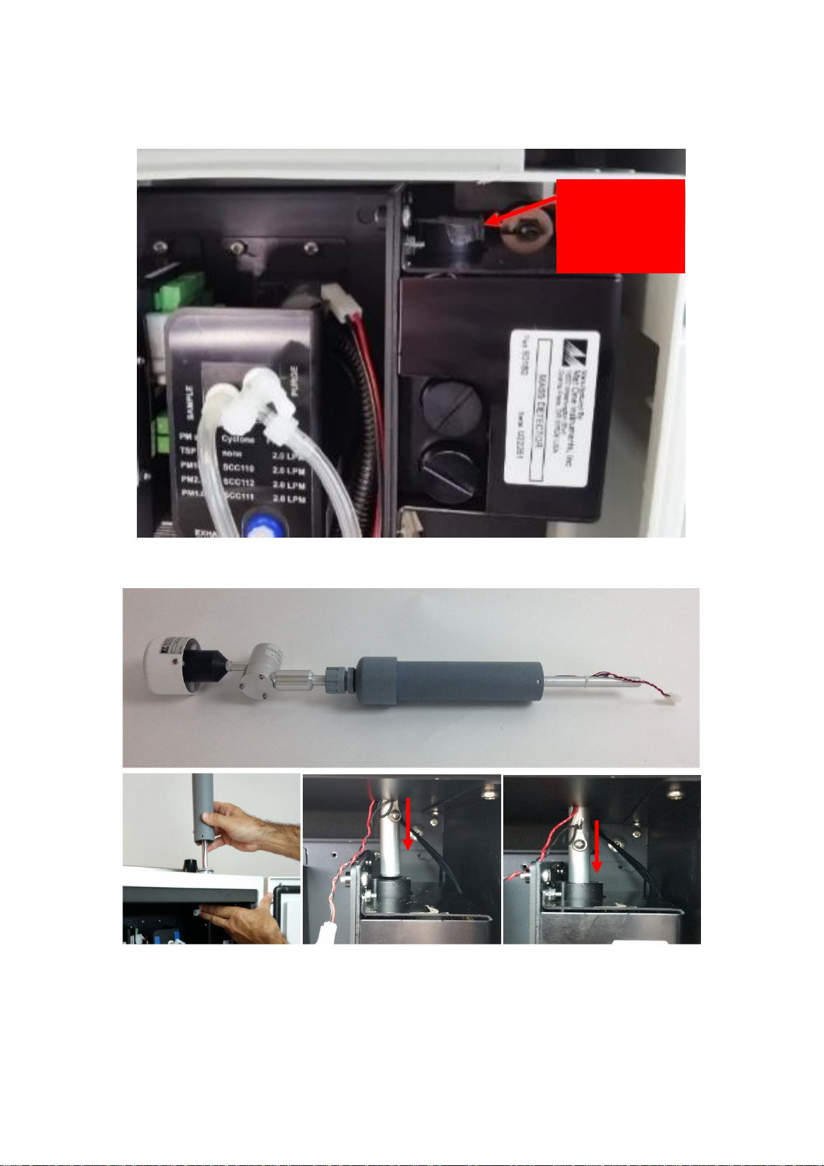
Figure 2-1 Particle sampling inlet parts including (L-R): inlet tube, cyclone adaptor, cyclone, TSP head.
Attach PM inlet
Turn off power to the monitor during this process by pulling out the 12 DC fuse as show in
Figure 2-8.
If not already fitted, attach a PM inlet O-ring to the aluminium retaining ring and apply a small
amount of lubricant.
Figure 2-2 Add the O-ring and a small amount of lubricant.
Inside the sampling inlet assembly has a sampling tube extending out of it. The sampling tube
has a thin film heater further up the shaft which is powered by the black and red cable exiting
the bottom of the assembly with white plug on the end.
Carefully thread the white plug through the PM inlet port on the roof of the monitor.
Continued next page.
MRK-D-0048 V4 Aeroqual Dust Sentry / AQS User Guide Page | 13
IMPORTANT The Particle Monitor ships from the factory with a thin film of tape or coloured
cap which protects the inlet, this must first be removed as shown in
Figure 2-3.
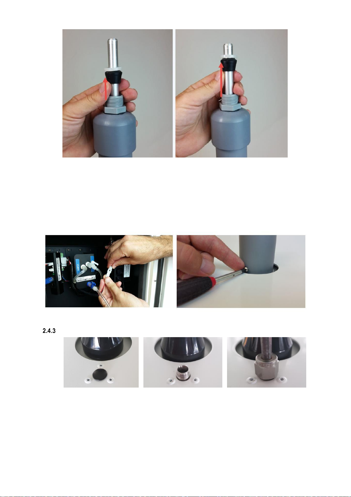
Figure 2-3 Remove the protective tape or cap from the PM inlet
Figure 2-4 Gently feed in the power cable and over the particle engine mounting bracket on the left. The
aluminium tube must push all the way into the PM module.
IMPORTANT Ensure sure that the aluminium inlet tube is pushed all the way into the
optical engine block.
If the aluminium tube does not fully push down in to the optical engine block, then create
more length in the aluminium tube by removing the grey retaining nut and then sliding up the
rubber grommet on the top of the inlet. Replace the nut after you have done this.
Remove
protective
tape or
coloured cap
MRK-D-0048 V4 Aeroqual Dust Sentry / AQS User Guide Page | 14
Figure 2-5 Create more length to the inlet by sliding the black rubber grommet up the tube.
You need to make sure you have correctly and securely inserted the aluminium tube fully in to
the optical engine block.
When you are satisfied the inlet is fully pushed in to the engine block, then connect the heater
plug on the inlet to the plug coming from the adjacent particle engine control module.
Insert the three supplied 6/32 UNC retaining screws to secure the inlet to the aluminium
retaining ring
Push the fuse holder in to the “On” position to begin flowing air through the inlet.
Then perform a leak check and flow check. See Section 6.5.6 and 6.5.7.
Figure 2-6 During field installation, secure the PM inlet using the retaining screws and plug in the heater
Attach gas inlet (AQS Only)
Figure 2-7 (L-R) Dust Sentry, Dust Sentry Pro come with insert. AQS supplied with Swagelok fitting.
The gas inlet is held by a ¼ inch Swagelok compression fitting.
Attach the inlet and perform a flow check to make sure the inlet is fitted correctly and the
sample pump is working properly.
When the AQS is sampling ambient air in the field, a Kynar inlet fitting with mesh is attached
to the Swagelok nut at the end of the sample cane.

MRK-D-0048 V4 Aeroqual Dust Sentry / AQS User Guide Page | 15
2.5 Power Requirements
The internal power requires regulated 12 VDC to maintain a constant pump speed. An external
mains to 12VDC power supply (Meanwell HLG80-12A 60W 12V) is fitted on the outside of the
enclosure and comes with an IP rated outdoor electrical plug. You must wire the other end of
the plug to mains power.
Where possible, visit the site and assess monitor location and suitability
AC power source
Both Mains and Solar power can be used, but these will need to be available and installed before the
monitor arrives When installing power outlets (110 VAC to 230 VAC) for the monitor, they should be
weatherproof and installed safely. Install 2 power outlets, 1 for the monitor and one for calibration
equipment.
NOTE: Aeroqual does not supply the mains power cable or the electrical plug for your local power
socket, you must supply this yourself.
DC power source
Occasionally mains AC power is not available at the site where the Monitor is installed and an
alternative power solution is required. More detailed information is in a Technical Note for remote
powering the monitors available from https://www.aeroqual.com/support/technical-documents
Wiring the power supply connector
1. Locate the power connector terminal which is situated outside the enclosure at the bottom. The
power supply will already be wired to the connector however the cable to connect to mains power
needs to be wired.
Caution: The high voltage mains supply must be wired by a certified electrician in
compliance with local electrical regulations.
A wiring color guide
is in section 12.3
3. Reconnect into the connector
ensuring the plugs are fitted securely
and the nut gland tightened.
Plug
Nut gland
Connector
Terminal block
Neutral
(Blue)
Earth
(Yellow/Green)
Live
(Brown)
2. Feed the power cable through the nut gland
plugs and connector and wire the cable to the
terminal block according to the diagram.
To separate the
connectors, twist the nut
gland to loosen the
terminal blocks, then pull
connectors apart
MRK-D-0048 V4 Aeroqual Dust Sentry / AQS User Guide Page | 16
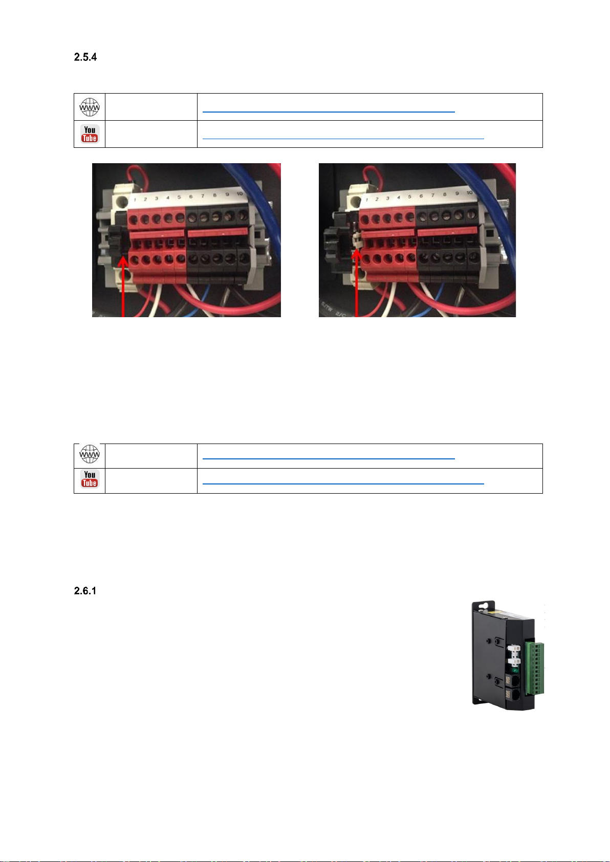
Powering monitor On/Off
NOTE: Pull the 12 VDC fuse out from the fuse holder “off position” before testing the mains
connection. See Figure 2-8.
Online reference
http://training.aeroqual.com/mod/page/view.php?id=623
Online video
YouTube Channel: Aeroqual Service and Maintenance playlist
12 V DC fuse pushed in, the “on” position
12 V DC fuse pulled out, the “off” position
Figure 2-8 The 12V DC fuse can be pulled out to turn off the monitor or pushed in to power the monitor
Push in the 12 DC fuse to the “on” position as shown on the left in Figure 2-8.
The pump/s will start and the ePC will boot up with a series of beeps.
The green power LED lights should light up on the modules when power is applied, this confirms the
power is being correctly delivered to the modules.
2.6 Wiring auxiliary sensors
Online reference
http://training.aeroqual.com/mod/page/view.php?id=625
Online video
YouTube Channel: Aeroqual Service and Maintenance playlist
NOTE: To check the operation of the third party sensor in your office or laboratory prior to site
installation it is not required to feed the cable through the gland.
External sensors such as weather stations and noise meters need to be wired to the green connector
plug on the front of the auxiliary module. To connect third party sensors such as weather sensors,
feed the cable through a free cable gland and wire to the green plug.
AUX module
An AUX module is used to provide power to an external sensor and to process data
from the sensor. The AUX module is shown to the right.
The AUX module uses a 12 way green connector plug to connect to the external
sensor. The cable from the external sensor is passed through a waterproof gland on
the underside of the monitors and then connected to the green plug on the front of
the AUX module. Each third party sensor requires a different wiring configuration.
See 2.6.2 Auxiliary sensor wiring diagrams.
When you are happy with the wiring then apply power, and log on to the Aeroqual
Connect software as described in section 4.1 Aeroqual Connect (via Direct WIFI /
LAN). After some minutes you should see the parameters associated with the third party sensor being
shown in the software in the APP “Configure Instrument”, view settings then the active sensor column.
To See the data, go to “Manage Data”, then Charts or Table, adjust the “Averaging Period” as
required.
NOTE: Retain the certificate of compliance that is shipped with the monitor.

MRK-D-0048 V4 Aeroqual Dust Sentry / AQS User Guide Page | 17
Auxiliary sensor wiring diagrams
IMPORTANT The auxiliary module orientation may vary, observe the correct numbering
order as labelled on the green connector.
Gill Ultrasonic Wind Sensor
Cirrus MK427 Noise Sensor
Vaisala WXT536 Weather Sensor
Met One MSO Weather Sensor
Novalynx Silicon Pyranometer
Online reference
training.aeroqual.com DM 1.3 Tech training Section 2.3
MRK-D-0048 V4 Aeroqual Dust Sentry / AQS User Guide Page | 18
3 Mounting and Site Positioning Guidelines
It is important that the positioning of the monitor is suitable so as to yield data which is representative
of that specific location.
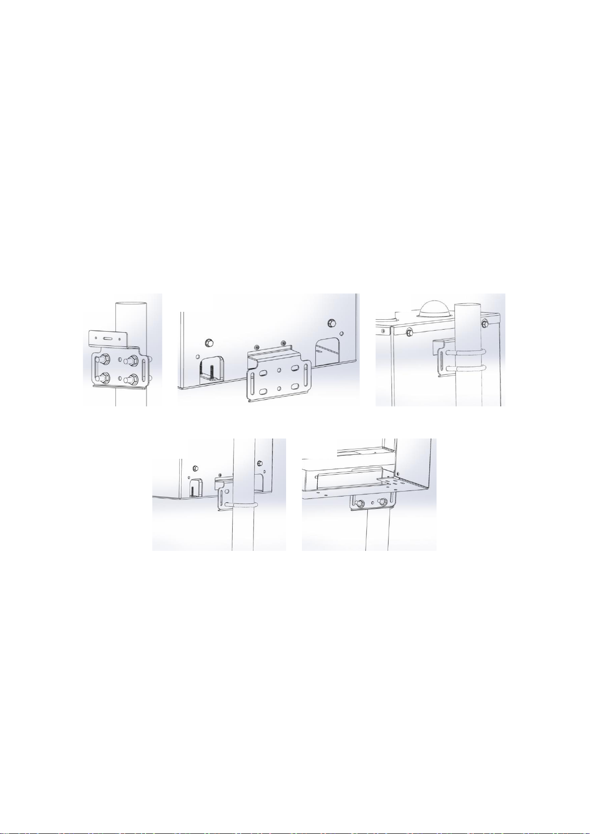
3.1 Mounting
The monitor comes with 2x mounting brackets and 3x U-bolts for 2 inch poles. The same brackets are
used for both pole and wall mounting. To wall mount the monitor the brackets are screwed into the
wall instead of using the U-bolts.
For pole mounting:
1. Secure top mounting bracket at a suitable height using 2x U-bolts provided
2. Fix lower mounting bracket to the Dust Sentry chassis with screws
3. Hang the monitor on the top mounting bracket
4. Place U-bolt through lower mounting bracket
5. Add nuts and washers and tighten the bottom U-bolt into position
NOTE: Only one U-bolt is used to secure the bottom bracket.
3.2 Inlet height
If monitoring is related to human exposure, the sampling inlet height should be positioned in
the “breathing zone”. This is located between 2 and 15 meters above ground level.
If monitoring is related to specific emission sources, the position of the sampling inlet can be
more flexible. It is more important that there is no obstruction between the approaching air
from the emission source and the sampling inlet.
If more than one monitor, or any other particulate instrument, is being used at the site, the
height of the inlets should be uniform.
If the monitor inlet is the highest point at the site, a lightning rod must be installed to prevent
damage to the unit during electrical storms.
3.3 Measurement Interference
The meteorological conditions of the site should be taken into consideration when positioning
the monitor. For example, there should be no obstruction to the air flow in the predominant
wind direction. A minimum clear sky angle of 120 degrees is recommended.
1.
2.
3.
4.
5.

MRK-D-0048 V4 Aeroqual Dust Sentry / AQS User Guide Page | 19
The inlet should be at least 1 meter away from any objects that could potentially influence the
airflow characteristics e.g. trees, vertical surfaces or walls.
Avoid overhead high-voltage cables which may cause electrical interference with the
sampling equipment.
Demolition/construction activities and change to normal transport patterns due to road works
etc. can significantly affect the data. Ensure a record of such events is kept to account for
unexpected peaks in concentration.
3.4 Safety
The intended data capture rate should be considered when positioning the monitor. If data
capture above 90% is essential, the unit should be located in an area which has 24 hour
access available.
The positioning should allow for routine maintenance checks to be performed safely by
personnel.
If using a tripod, ensure the tripod legs are bolted to the ground to prevent the unit from
falling.
Ensure the monitor is in a secure location to avoid vandalism or theft.

MRK-D-0048 V4 Aeroqual Dust Sentry / AQS User Guide Page | 20
4 Connectivity
The monitors use an industrial embedded PC (ePC) for data logging and monitor control. A cellular
modem can be fitted underneath the ePC to facilitate remote connection and support from Aeroqual
technical support. –see section 4.2.2 Connecting using a cellular modem.
There are two ways to connect to your monitors:
Aeroqual Connect (via Direct WIFI / LAN) for initial set up and when access to the internet
is limited;
Aeroqual Cloud (via Network WIFI / Modem) for remote access, visibility of all your
monitors, and remote technical support from Aeroqual Care.
Aeroqual highly recommends every monitor is connected to Aeroqual Cloud for the best user
experience, additional data features, and Aeroqual Care.
Engineers who need to perform service or data analysts who need to view or download data can do
so using a web browser on their PC, tablet or smart phone. There is no software to download and
install.
Data Security
The data belongs to you. We look after it in the same way that a bank looks after your money. Who
you let access your data is entirely up to you –our job is to carry out your instructions.
If you do choose to store data with us, then here are some of the security assurances we provide:
We use only ISO 27001 approved data centres
Infrastructure is monitored and protected 24/7
Data is accessed via a secure website with 256-bit SSL encryption
User defined passwords
4.1 Aeroqual Connect (via Direct WIFI / LAN)
Aeroqual Connect contains all of the tools necessary to view and download the data and maintain and
calibrate a single monitor.
No internet connection is required for Aeroqual Connect. Aeroqual Connect is always running on the
monitor and can be accessed via WIFI through an internet browser on any device, there is no
software to install.
Figure 4-1 Aeroqual Connect Home page
Connect to Aeroqual Connect via Direct WIFI
A few minutes after powering on, you should see a new WIFI network in your device’s list of WIFI
networks. The WIFI name (SSID) will match your serial number, connect to this network using the
password below.
WIFI SSID: DS DDMMYYYY-XXX or AQS1 DDMMYYYY-XXX
Password: Aeroqual
This manual suits for next models
2
Table of contents
Other Aeroqual Measuring Instrument manuals


Popular Measuring Instrument manuals by other brands

AMO
AMO AMOSIN WMI-300 Installation and mounting instructions

ELKOR
ELKOR WattsOn-MCM Installation & user guide

SPY
SPY PJM Pocket JeepMeter operating instructions

Mitutoyo
Mitutoyo Digimatic MDC-S user manual

Pepperl+Fuchs
Pepperl+Fuchs PMI360D-F130-IE8-V15 manual

Comet
Comet COMMETER C3631 instruction manual


De Nora
De Nora 200 Series instruction manual

Dwyer Instruments
Dwyer Instruments WDPM-002 Specifications-installation and operating instructions

Sealey
Sealey AK9637D.V2 instructions

Vega
Vega VEGACAL 65 operating instructions

KYORITSU
KYORITSU KEW SNAP 2002PA instruction manual

Fieldpiece
Fieldpiece SC66 Operator's manual