Moretti Design ALADINO ALL STYLE User manual

USER MANUAL
WOOD STOVES
WOOD

2
INDICE
1 - General information
2 - Warnings
3 - Safety distances
4 - Installation
4.1 - Chimney installation
4.2 - Connecting the stove to the chimney
5 - Permitted fuels
6 - Instructions for a safe use of the stove
7 - Using the stove
7.1 - Combustion
7.2 - First ignition
7.3 - Subsequent ignitions
7.4 - Cleaning the glass
7.5 - Removal of the ashes
8 - Cleaning and maintenance
9 - Hestings fans
10 - Disposal
10.1 - Packaging
10.2 - Disposal of the stove
11 - Warranty conditions
12 - Technical features
13 - Data sheets and measurements
13.1 - ALADINO WOOD ALL STYLE
13.2 - CLESSIDRA WOOD ALL STYLE
13.4 - CLESSIDRA WOOD STONE
13.5 - ELEGANCE WOOD ALL STYLE
13.8 - ERGONOMIC WOOD GLASS
14 - Asthetic component assembly - ALADINO WOOD ALL STYLE
15 - Asthetic component assembly - CLESSIDRA WOOD ALL STYLE
16 - Asthetic component assembly - CLESSIDRA WOOD STONE
17 - Asthetic component assembly - ELEGANCE WOOD ALL STYLE
18 - Asthetic component assembly - ERGONOMIC WOOD GLASS
3
4
4
5
5
8
9
9
9
9
10
10
10
10
11
11
11
11
11
12
12
12
13
13
13
14
14
15
17
20
24
25

3
1 - GENERAL INFORMATION
The WOOD series stoves by MORETTI DESIGN
have been conceived and created to be a source
of heating inside residential environments.
The extreme care of design and the extraordinary
craftsmanship quality, combined with the specta-
cular uniqueness of the flame developed by the
wood, make MORETTI DESIGN stoves an ele-
gant furnishing accessory capable of enhancing
any environment with its aesthetics.
The stoves have been designed for burning wood
for heating indoor environments. The air is heated
by natural convection and by radiation. In this way
the stove is able to quickly heat up even very cold
rooms.
The natural convection heating principle ensures
that the room air enters the lower part of the stove
and is heated in the convection space consisting
of a double shell coating; the air flow is then retur-
ned to the environment through the holes located
in the upper part of the stove.
The heat generated by radiation is instead that
released into the environment directly from the
surfaces of the stove. The largest source of heat
by radiation is the glass surface.
The stoves are made with a steel structure, while
the interior of the combustion chamber is made of
vermiculite and refractory bricks. The external
surfaces are instead in steel, majolica and glass.
The door is made with a double glass: the inter-
nal one is a ceramic glass resistant to high tempe-
ratures and thermal shocks; the outer one is a
"magic" glass that lights up with the appearance
of the flame, remaining black instead when the
flame is extinguished.
At the bottom of the combustion chamber there is
a cast iron grid, below which there is a com-
partment for ash collecting.
To allow an optimal entry of combustion air into
the combustion chamber, there are primary and
secondary air inlets: primary air is necessary for
ignition and its passage takes place through the
cast iron grid; the secondary air flows on the glass
and above the grid and creates a self-cleaning
effect for the glass; the secondary air also passes
through the upper part of the stove and burns the
unburnt gases.
The appliance is supplied with the majolica ae-
sthetic parts not assembled, but contained in a
special package in order to better preserve them
for transport. To assemble the majolica tiles, fol-
low the instructions given in the dedicated section
of this manual.
External door
Door handle
Air adjusting lever
Majolica top
Top smoke outlet
Stainless steel
grid
Glass cleaning air
conveyor
Combustion chamber

4
Degree of
flammability
Building
materials
A - Not inflammable
Granite, sandstone,
Strongly porous concrete,
bricks, ceramic tiles,
special plasters
B - Almost flammable Wood-concrete
C1 - Hardly
flammable Plywood,
C2 - Medium
lammable
Chipboard, cork,
rubber,
C3 - Facilmente
infiammabile
Polistirolo, poliuretano,
fibre di legno
2 - WARNINGS
This manual provides useful information for the
installation, function and maintenance of the sto-
ve, so as to allow a correct and safe use. We the-
refore invite you to read the manual with extreme
accuracy, paying particular attention to the follo-
wing warnings.
The manual is an integral part of the stove, it is
recommended to keep it with care and to always
near the appliance for a quick consultation, when
necessary. In case of loss or damage, request a
copy from your dealer.
MORETTI DESIGN wood stoves are made accor-
ding to the indications contained in the European
product standard (EN 13240: 2007), using absolu-
te quality components.
The installation and maintenance of the stove
must be carried out by qualified personnel accor-
ding to the law (DM 22 January 2008, n. 37). All
local regulations, including those referring to na-
tional and European standards, must be respec-
ted in the installation and use of the appliance.
The information contained in this manual must be
observed attentively in order to ensure a safe use
of the stove. The manufacturing company is not
responsible for damage caused to people, ani-
mals or things deriving from an incorrect use of
the appliance or from failure by the customer or
the installer to comply with the indications, obliga-
tions and prohibitions established by applicable
laws.
The installer will assume full responsibility for the
definitive installation and consequent proper func-
tioning of the stove.
It is forbidden to make any type of modification to
the appliance without the manufacturer's prior au-
thorization. Use only original spare parts recom-
mended by the manufacturer.
The stove must not be used as an incinerator or in
any other way other than that for which it was de-
signed. No other fuel than those expressly recom-
mended in this manual must be used. Do not use
liquid fuels.
The use of the stove by children or people with
reduced physical, sensory and mental abilities is
prohibited, unless they are supervised and in-
structed in the use of the appliance by a person
responsible for their safety. Children should be
checked to make sure they don't play with the ap-
pliance.
Each stove bears an identification label plate, con-
taining the technical data and the serial number,
such as the one shown below.
3 - SAFETY DISTANCES
When a stove is installed near class B, C1 and C2
flammable substances, the safety distance from
the front (as well as from the glass surfaces) must
be 800 mm, the rear safety distance of a minimum
of 200 mm and the lateral safety distance of at
least 500 mm.
If the stove is installed in a room with class C3
flammable substances, the measures indicated
above must be doubled.
The correct safety distances for the installation
are shown on the label plate of each product. Ta-
ble 1 shows some materials with their respective
classes
Table - Information regarding the flammability
levels of some materials.

5
4 - INSTALLATION
The installation of the appliance must be carried
out by qualified personnel and in compliance with
all European, national and local regulations cur-
rently in force. For a correct installation, comply
with the instructions provided below:
• The stove must be installed on a floor with
an adequate load capacity. The weight of
the stove is shown on the label plate glued
on the back of the appliance. If the weight
is excessive compared to the load capacity
of the floor, install a weight distribution pla-
te.
• If the stove is installed in a room with a
flammable floor, a plate of non-flammable
material must be placed under the applian-
ce, the size of which must exceed the base
of the stove by 30 cm on the front and 10
cm on the other three sides. The plate must
have a minimum thickness of 2 mm.
• The room in which the stove will be instal-
led in must be ventilated with sufficient
fresh air to replenish the air burnt during the
combustion. For this reason, an air intake
must be made near the stove outside the
house with a minimum surface area of 200
cm². The air intake must be protected by a
grid which must be made in such a way that
it cannot be obstructed.
• The combustion air inlet can also be con-
nected directly to the outside, in order to
improve the air supply and to avoid indoor
environment smoke spillage in case of wind
blowing back into the chimney.
• When installing the stove, adequate spaces
must be provided to allow normal mainte-
nance and cleaning operations and access
to the chimney.
4.1 - Chimney installation
The stove must be connected to a chimney with a
draft not less than 12 Pascal. The installer or the
authorized maintenance technician must ensure
that the chimney and its connection are carried
out correctly, in accordance with the sector regu-
lations (UNI 10683 and UNI EN 13501-1).
The stove must have its own dedicated chimney:
it is forbidden to connect the stove to a chimney
already serving another appliance.
Below are some examples of chimney installa-
tions.

6

7
For the connection to the chimney, we recommend
the use of stainless steel pipes in compliance with
current regulations, without reductions, and with a
maximum inclination of 45 °. It is recommended
not to use flexible metallic and / or fiber cement
materials.
The external parts of the chimney must be insula-
ted in order to avoid condensation and the forma-
tion of creosote on the internal walls of the chim-
ney, which in the long run reduces its section and
therefore the ability to evacuate the smoke.
The chimney must be made of stainless steel pi-
pes insulated with material resistant to high tem-
peratures.
It must be maintained as much vertical as possible
by minimizing curves (maximum 45 ° inclination)
and avoiding bottlenecks and changes of section
capable of producing turbulence and pressure
losses.
αAHZ
Roof pitch
Distance between the
roof axis (ridge) and up-
stream side of chimney
Minimum height from roof
outlet
(h minimum)
Reflux area height
15° 1,85 m 1,00 m 0,50 m
30° 1,50 m 1,30 m 0,80 m
45° 1,30 m 2,00 m 1,50 m
60° 1,20 m 2,60 m 2,10 m

8
The chimney must preferably have a round sec-
tion in order to minimize pressure drops and facili-
tate the evacuation of combustion fumes. If a
square or rectangular section duct is used, the
edges must be rounded with a ratio between the
sides equal to 1.5.
The internal walls must be smooth and waterproof
to avoid the deposit of unburned materials and the
absorption of condensate.
Contact between the chimney and flammable or
combustible materials must be avoided, either
through the use of suitable insulating materials or
through the creation of an air gap.
It is extremely important to check the exit of the
chimney on the roof. In this sense, refer to the
figures and table on page 7.
4.2 - Connecting the stove to the chimney
MORETTI DESIGN wood stoves provide the pos-
sibility of connecting the chimney or on the top or
on the rear (see the figures below).
During production, a mouthpiece (male) is instal-
led on one of the two outlets for the connection of
the pipe to the chimney, while the other outlet is
closed with a rectangular plate.
Rear smoke
outlet
Top smoke
outlet
Combustion
air inlet
On the external aesthetics (top and rear), there
are circular pre-holes in correspondence with the
smoke outlets
For the connection of the chimney, proceed as
follows:
• break the pre-hole in the aesthetics on the
smoke outlet you want to use (top or rear);
• If necessary, dismantle the mouthpiece for
the connection to the chimney and position
it on the desired outlet;
• use the metal plate that may be removed to
close the unused smoke outlet.
It is important to make sure that with the disas-
sembly and reassembly of the mouthpiece and
closure plate, the unused smoke outlet is always
correctly closed, in order to avoid smoke leakage
into the environment, and that the gaskets are
always present.
WARNING: it is possible that from production the
mouthpiece is positioned on the rear outlet.
WARNING: it is advisable to carry out any con-
nection to the chimney without the majolica or
glass aesthetics assembled, in order to avoid da-
maging them.
Top smoke
outlet opening
Smoke outlet rectangular
closing plate

9
7 - USING THE STOVE
7.1 - Combustion
For an optimal combustion, it is essential that the-
re is a sufficient intake of combustion air inside the
combustion chamber. Therefore, it is appropriate
to verify that the external air intake is present and
is not obstructed, and that the combustion air inlet
tube on the rear of the stove is free from obstruc-
tions.
For a more efficient combustion, there are several
combustion air inlets inside the combustion cham-
ber: one primary air inlet and one secondary air
inlet.
The primary air is essential during the lighting up
phase and is fed into the lower part of the combu-
stion chamber; The secondary air is instead fed
into the upper part of the combustion chamber
and serves to improve combustion itself and help
keep the door glass clean.
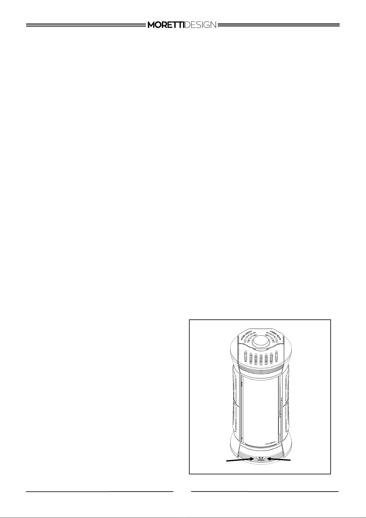
Both primary and secondary air are adjustable.
For an efficient combustion it is essential to regu-
late the right amount of air in the combustion
chamber, so as to also reduce emissions of
harmful gases into the environment. To best ad-
just primary and secondary air, act on the levers
shown in the figure below.
To open the air to the maximum, position the le-
vers towards the outside of the stove.
To completely close the air, position the levers
towards the center of the stove.
5 - PERMITTED FUELS
The stoves are designed for using wood. For a
high efficiency, the use of wood with humidity lo-
wer than 20% is recommended. For drying wet
wood, storage in a well-ventilated room for a pe-
riod of 2 years is recommended.
If wooden logs are used, they must be kept in a
dry environment so as not to compromise them
with excessive humidity. The use of excessively
damp wood or logs leads to a loss of efficiency of
at least 20%, to a higher fuel consumption and to
tar production which further reduces the efficiency
of the stove.
6 - INSTRUCTIONS FOR A SAFE USE
OF THE STOVE
It is absolutely forbidden to use flammable liquids
for lighting up and using the stove. It is also forbid-
den to burn any type of plastic, wood containing
chemical materials and other chemically treated
wood waste. Use only the permitted fuels listed in
paragraph 5.
Some surfaces of the stove, especially the front
glass areas, are subject to severe overheating and
can cause serious burns on touch. It is therefore
recommended to handle the stove with the utmost
attention when it is lit up or during the minutes
immediately after the flame is put out.
It is prohibited to place flammable materials on the
stove when in use or when it is still hot, it can igni-
te and cause a fire. It is forbidden to place any
type of container containing cold water on top of
the stove.
It is recommended to be extremely cautious when
removing hot ash. Hot ash must not come into
contact with flammable substances, for example
when they are emptied into a dustbin.
In the event the chimney catches fire, immediately
extinguish the flame in the stove by closing the
combustion air inlet through the special levers
(see paragraph 6.1), remove the hot ashes with a
small shovel and deposit them in a non-flammable
container. Contact the fire brigade immediately.
MORETTI DESIGN will not be held responsible for
any damage to people, animals or things resulting
from unauthorized modifications to the appliance
or from failure to comply with the indications provi-
ded here.
Secondary
air lever
Primary air
lever

10
In this span of time, the applied coating is burned,
stabilized and the adequate strength, hardness
and abrasion resistance is obtained. During this
process, the room must be intensely ventilated to
disperse the fumes. Do not touch the stoves sur-
face during combustion, the paint may be dama-
ged.
7.3 - Subsequent ignitions
Before each ignition, clean the ash grid; then, put
crumpled paper, wood chips or small logs on the
base of the combustion chamber. Solid firelighters
can also be used. Never use liquid gasoline-type
flammable substances to light.
Place wood in quantities not exceeding 2 kg. Igni-
te the paper or wood chips and close the door
tightly.
When igniting, we recommend that you keep both
the primary air lever and the secondary air lever
fully open (positioned towards the outside of the
stove). This will help develop earlier the flame.
Once the stove is lit, in order to control the flame,
and then the combustion air inlet, first act on the
primary lever until it is eventually closed, and se-
condly act on the secondary air. In particular, the
primary air must be reduced to a minimum when
the stove has reached an efficient combustion
state, and the flame must be regulated by opening
or closing the secondary air lever.
7.4 - Cleaning the glass
The use of a proper fuel, a sufficient air inlet for
combustion (in particular secondary air) and an
adequate draft in the chimney, affect the preser-
vation and cleanness of the glass of the door.
In the case of dirty glass, clean it when the stove
is cold with suitable detergents and with a soft
cloth that cannot scratch the glass itself.
7.5 - Removal of the ashes
In the event that the stove is in operation for a
long time, it is advisable to move the ash over the
grid so as to allow it to fall into the drawer below.
It is also recommended not to let the ash drawer
become too full, which could hinder the passage
of air under the grid and create subsequent com-
bustion problems.
The exact setting of the levers for the adjustment
of the combustion process can not be determined
uniquely. The optimal amount of combustion air is
influenced by a series of factors: the type and hu-
midity of the fuel, the draft of the chimney, the
conditions of external pressure, etc. Therefore the
user must adjust the combustion process (flame
intensity and quality) according to the existing
conditions. To obtain maximum efficiency, the
right lever must be positioned all the way back
(towards the stove) to completely close the prima-
ry air and the left lever all the way forward to fully
open the secondary air. Use a triangular shaped
log weighing about 1.5 kg and about 220 mm long
with jagged edges and support part that leans on
the grid (see images)
7.2 - First ignition
The first ignition of the stove must be done using
soft wood, so that the temperature rises slowly. It
is important, once the stove is lit, that a live flame
is maintained for at least an hour.
22cm
Jagged edges

11
9- Heating fans
To activate the fans, connect the cable to the rear
connector and to the power socket.
The three-position switch on the back of the stove
allows you to activate the fans at minimum speed
(Position I) or maximum speed (Position II).
In position 0 the fans are off and are activated
automatically only if the stove temperature
exceeds a preset limit.
10 - DISPOSAL
10.1 - Packaging
The stove is delivered assembled on top of a
wooden pallet with protective packaging. You can
dispose of the packaging in the following way:
• Disassemble the wooden base (can also be
used to ignite the stove);
• Throw the rest of the packaging in a bag or in a
separate waste collection point;
• Deliver the cardboard to a collection point.
10.2 - Disposal of the stove
In the event of cessation use of the stove, throw
the coating, glass and gaskets in municipal waste,
paying attention to differentiate different materials.
The majolica tiles must be placed with building
waste. The rest of the stove, i.e. the metal body
together with cast iron parts, can be delivered to
scrap metal collection points.
In any case, it is recommended to refer to the
specific waste collection and disposal regulations
of the individual municipalities.
The stove must be serviced at least once a year
(after the winter season) or more frequently in ca-
se of intensive use or use of poor quality fuel; the
stove must always be cold before cleaning.
During the cleaning procedure, any soot and ash
in the smoke outlet and combustion chamber
must be removed. The ash grid must be cleaned
and left without obstacles between the cracks.
Any parts of the internal vermiculite coating that
have fallen should also be repaired.
The completeness of the inner lining must also be
monitored during the winter season. The gaps
between the individual refractory walls are used
for thermal expansion and to prevent cracks; the
gaps must not be filled in any way (for example
with filling).
In any case, the cracks on the vermiculite boards
do not cause the loss of their functionality, unless
they have fallen completely. Therefore the mere
presence of small cracks is not a reason for com-
plaint.
To clean the external majolica tiles, use special
and non-aggressive detergents to avoid damaging
the paintwork. Use soft cloths to avoid scratching
the surfaces.
Smoke
deflector
Combustion
chamber
WARNING: Before emptying the ash drawer,
check that the ash is completely cold and does
not contain any lit remains of fuel, which could
cause a fire in the dustbin. Burnt ash can be used
for compost or as a fertilizer.
8 - CLEANING AND MAINTENANCE
At least once a month, the smoke deflector must
be removed to clean it of any soot that has accu-
mulated in its upper part.
The deflector is located in the upper part of the
combustion chamber (figure below); to remove it,
access it from the combustion chamber door, then
lift it slightly and tilt it in order to get it out of its
final position.

12
11 - WARRANTY CONDITIONS
The buyer is the owner of rights provided by the
National legislation that guarantees consumer
goods. Therefore the seller guarantee’s the buyer
against any lack of conformity which becomes
apparent within a period of 2 years from the date
of purchase. In case of conformity defects within 2
years from the purchase, the seller will repair or
replace the product within a reasonable time, tak-
ing in account the nature of the product, the pur-
pose for which it was acquired and the proce-
dures that must be undertaken to restore the con-
formity. The resolution of any non-conformity is
not applicable in the following situations:
• failed compliance in following the installation
instructions and use;
• accidental causes and negligence of the buyer;
• modifications or repairs carried out by unau-
thorised personnel;
• improper maintenance;
12 - TECHNICAL FEATURES
• operated or stored out of specified environ-
mental conditions for the product;
• use of accessories not sold by the seller and/or
parts not designed to be used with the product.
The warranty doesn’t include those parts and ma-
terials subject to wear and tampering. It doesn’t
cover any kind of brickwork or plumbing, including
disassembly and reassembly of the product. The
warranty is effective only if the warranty registra-
tion card, enclosed with the manual, is filled in
and posted within 8 days from the date of pur-
chase. Moretti Design disclaims any responsibility
for incorrect installation or tampering and unau-
thorized interventions.
Items not covered by warranty
• Glass
• Majolica
• Internal refractory bricks or vermiculite
U.M
ALADINO
WOOD ALL
STYLE
CLESSIDRA
WOOD ALL
STYLE
CLEESIDRA
WOOD
STONE
ELEGANCE
WOOD ALL
STYLE
ERGONOMIC
WOOD
GLASS
NOMINAL
POWER kW 11,4 11,4 11,4 11,4 11,4
WEIGHT kg 200 200 190 200 190
SMOKE OUT-
LET mm 150 150 150 150 150
AIR INTAKE mm 80 80 80 80 80
HEIGHT mm 1157 1234 1234 1147 1261
WIDTH mm 619 598 598 546 588
DEPTH mm 620 599 599 590 580
EFFICIENCY %87,8 87,8 87,8 87,8 87,8
CO mg/m³ 13% O2596 596 596 596 596
CO % 13% O20,047 0,047 0,047 0,047 0,047
NOX mg/m³ 13% O284 84 84 84 84
DUST mg/m³ 13% O210 10 10 10 10
SMOKE TEMP. °C 169,4 169,4 169,4 169,4 169,4
SAF.DISTANC
E L-P-Fmm 550-530 550-530 550-530 550-530 550-530

13
13.1 - ALADINO WOOD ALL STYLE
13 - DATA SHEETS AND MEASUREMENTS
13.2 - CLESSIDRA WOOD ALL STYLE
13.3 - CLESSIDRA WOOD GLASS - CLESSIDRA WOOD STONE

14
13.4 - ELEGANCE WOOD ALL STYLE
13.5 - ERGONOMIC WOOD GLASS

15
14 - AESTHETIC COMPONENT ASSEMBLY - ALADINO WOOD ALL STYLE

16
follows ASTHETIC COMPONENT ASSEMBLY - ALADINO WOOD ALL STYLE

17
15 - ASTHETIC COMPONENT ASSEMBLY - CLESSIDRA WOOD ALL STYLE

18
follows ASTHETIC COMPONENT ASSEMBLY - CLESSIDRA WOOD ALL STYLE

19
follows ASTHETIC COMPONENT ASSEMBLY - CLESSIDRA WOOD ALL STYLE

20
1 (STONE)
2 (STONE)
X4
X4
16 - ASTHETIC COMPONENT ASSEMBLY - CLESSIDRA WOOD STONE
This manual suits for next models
5
Table of contents
Popular Wood Stove manuals by other brands

Blaze
Blaze B600 operating instructions

Napoleon
Napoleon NZ6000-1 Installation and operating instructions

Blaze King
Blaze King PF-202 Owner's installation and operation book

Pacific energy
Pacific energy ALDERLEA T4 LE Operating and installation instructions

SCAN
SCAN 58 - series Assembly and instruction manual

Justus
Justus Mino I Operating and installation instructions

SBI
SBI AC01291 installation instructions

HUUM
HUUM HIVE WOOD Series Installation and user instructions

TermaTech
TermaTech TT23 Series User and mounting manual

Vogelzang International
Vogelzang International VG450EL owner's manual

Enerzone
Enerzone Solution 3.4 user manual

Drolet
Drolet Eldorado DB02610 Installation and operation manual