Justus Mino I User manual

293 2925 000 · 1089
Operating and Installation
Instructions for
Wood Burning Stoves
EN
JUSTUS
Mino I

2
EN
Table of Contents
Welcome 3
1. Description 5
2. General 5
2.1 External combustion air supply 5
2.2 Design 6
3. Flue tube connection and
setup of the wood burning stove 6
3.1 Connection of the ue tube 6
3.2 Setup of the wood burning stove 7
4. Technical data 8
5. Operating the wood burning stove 9
5.1 General information on safety 9
5.2 Air control 9
5.3 Suitable fuels 10
5.4 Commissioning 10
5.5 Heating with lignite briquettes 11
5.6 Heating during the transitional period 11
5.7 Maximum input quantity and air
adjustment with NHO 11
5.8 Emptying ashes 11
5.9 Cleaning and maintenance 12
5.10 Chimney re 13
6. Room heating capacity (DIN 18893) 13
7. Use in Smoke Control Areas 14
7.1 The Clean Air Act 1993 and Smoke
Control Areas 14
7.2 Modications to the air controls for
use in Smoke Control Areas 14
7.3 Suitable fuels 15
7.4 Refuelling on to a low rebed 15
7.5 Fuel overloading 15
7.6 Operation with door or dampers
left open 15
JUSTUS factory guarantee 16
Energy Label and Product Data Sheet
according to EU regulation 17
Declaration of performance 18
CE mark 19
Appliance parameters* Rear cover
*Please note:
When ordering spare parts and in the
event of any service call-outs, please
always specify the model number of
your appliance.
It is worth noting down the version of
your new wood burning stove now in the
circular eld provided in the table on the
page listing the “Appliance parameters”.
Thank you!

3
EN
Dear Customer,
JUSTUS wood burning stoves offer you sophisti-
cated and reliable technology, functionality and an
attractive design.
If, despite our careful quality checks, you find
anything you are not happy with, please contact
our central customer service team who will be
happy to assist you.
If you would like to enter a customer service
order, please have the following information
ready:
Type and serial number
Fabrication number / Inspection stamp, date:
(see the back of these operating instructions)
Identification Code
Date of purchase
A photo of the back of this manual or of the
nameplate
A photo of the fault
With this information, the customer service
order can be processed very quickly!
If you would like to contact us by email or
telephone, please have the above information
ready, so the processing of your request can
be carried out quickly and easily.
JUSTUS GmbH
Oranier Strasse 1
35708 Haiger
Germany
Telefon: +49 (0) 27 71 / 2630-0
Kundenservice / Ersatzteile
email customer
service: [email protected]
email spare parts:
Telephone: +49 (0) 27 71 / 2630-360
All services can be contacted
Mon - Thu: 8.00 - 17.00 h
Fri.: 8.00 - 15.00 h
*Please note:
Outside of Germany, please contact
your local distributor for customer ser-
vice and requests related to spare parts.
You can nd our ofcial distribution part-
ners on our website www.JUSTUS.com.
WARNING!
Riskofreduetotheuseof
non-original spare parts!
The use of rebox linings with
insufcient thermal properties may cause over-
heating of surrounding walls and furnishings!
Use only original spare parts!

4
EN
Please note:
Before setting up and operating this appliance, check for any transport
damagetothefunctionalparts(airslide,lining,seals,reboxdoor,pipe
supports, etc.).
If any such defects are found, please contact our customer service team.
Thisreplacemustnotbealteredinanyway! The purchaser and operator
ofthiswoodburningstoveisobligedtolearnhowtohandleitcorrectly
by reading these instructions. Our guarantee of fault-free function shall
immediately be rendered voidifthefollowingguidelinesandinstructions
are notcompliedwith. Thank you for your understanding.
Theseoperatinginstructionsfamiliariseyouwiththefunctionandhan-
dlingofthestoveandarepartofthereplacepackage.Keeptheoper-
ating instructions in a safe place so that you can remind yourself of the
correctoperatingprocedureswhenstartinganewperiodofheating.
Typetestedinaccordancewith
EN 13240
Section 15a B- VG Austria
Model 1
Directivesandstandardsthatmustbecompliedwith:
EN 12828 Heating systems in buildings
DIN 13384 Thermal and uid calculation methods
for chimneys
DIN 18160 Domestic chimneys, requirements, planning & design
VDI 2035 Prevention of damage caused by corrosion and scale formation
in water heating systems (only for appliances transporting water)
1. BImSchV Ordinance on Small Firing Installations
FeuVo Firing Directive
Boiler room guidelines
Regional building regulations
If applicable: Electrical connections must be carried out by specialist electricians as
specied by VDE
Thedegreeofefciencyand
emission values can be found
in the Declaration of Conformity
included in these instructions.

5
EN
1. Description
The wood burning stove is made of a welded
steel construction. The central section fea-
tures the rebox, which is lined with safety
panels. The ash box is located below a sturdy
cast iron trivet. Below this is a space for stor-
ing wood.
Woodburningstovesofthisdesign work using
convection, i.e. the surrounding air is sucked
in by the convection shafts built into the stove,
heated to a high temperature and then blown
back out into the living area.
This wood burning stove has been tested in
accordance with EN 13240.
2. General
Your wood burning stove must be set up with
strict adherence to the relevant regional build-
ing regulations and following consultation with
the local professional chimney sweep.
Once installed, he will also check that the re-
place is connected correctly.
During operation, a replace will draw oxygen
from the room in which it is set up. It is there-
fore absolutely essential to ensure an ade-
quate supply of fresh air to this room.
If the stove is set up in rooms with particularly
tightly-closing windows and doors, malfunc-
tions cannot be excluded.
If you are uncertain whether there is sufcient
air available for the stove in the room in which
you plan to set it up, ask your chimney sweep
for advice.
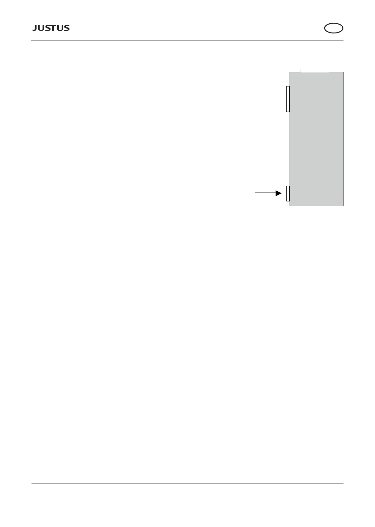
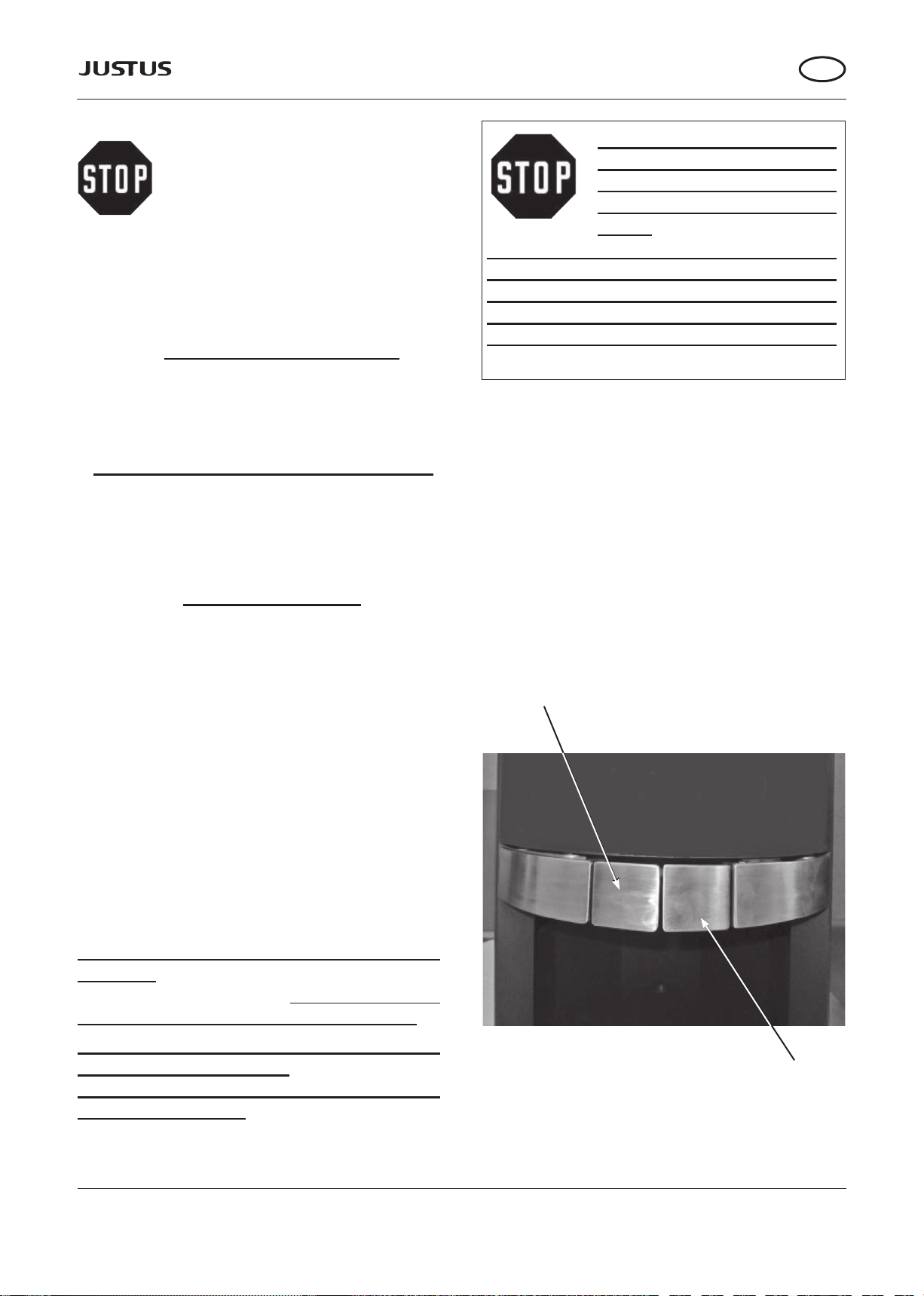
2.1 Externalcombustionairsupply
Ifnecessary,thewoodburningstovecan
beequippedwithaconnectionforanex-
ternal combustion air supply
(See Fig. 1):
For especially well-insulated rooms, an air
supply from outside can be connected. The
connection pipe required for this is available
as an accessory.
Wood burning
stove
Connection for
external combustion
air supply
Rear ue
tube opening
Upper ue tube opening
Fig. 1
When attaching an external combustion
air supply, ensure that the pipes are tightly
sealed!
The combustion air is supplied exclusively via
a supply pipe with a ND of 100 mm, tted dur-
ing installation. The air pipe should be made
from smooth steel or plastic (drainage pipe).
The full length of the pipe should be no longer
than 6 m, have no reductions in the bore di-
ameter and include no more than 3 90° elbow
pieces.
A safety grille attached in front of the exter-
nal air supply opening must not be able to
accidentally restrict or occlude the supply air
cross-section.
It can be connected to a suitable air exhaust
chimney.
In every case, care must be taken to ensure
that the combustion air requirement of around
30 m3/h is met at a feed pressure of 4 Pa.
When not in use, all air slides should be kept
closed to ensure that no cold air is able to cir-
culate via the chimney. The potential build-up
of condensation can be avoided
by insulating the air pipe.
The chimney draught must be able to over-
cometheadditionalresistancesofaring
systemequippedwiththissetup.
Table of contents
Popular Wood Stove manuals by other brands

RAIS
RAIS attika NEXO 100 GAS installation guide

WoodPro
WoodPro WS-TS-1500 owner's manual

Contura
Contura C 586W installation instructions

Palazzetti
Palazzetti EVA GENERAL INFORMATION - WARNINGS - INSTALLATION - MAINTENANCE

Lopi
Lopi 1250 Republic owner's manual

Panadero
Panadero CAPRI 3V Usage and maintenance instructions