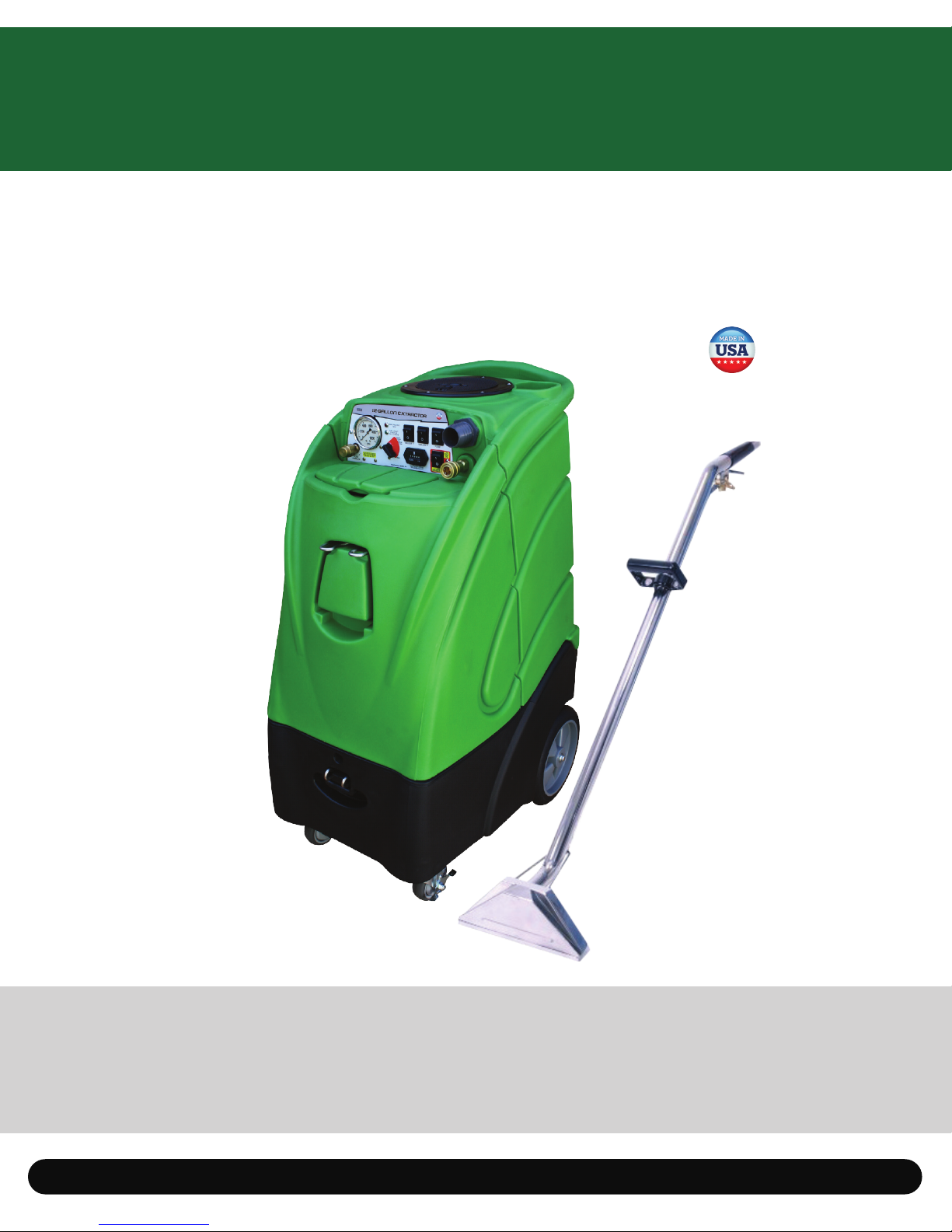
12 Gallon Extractor 12 Gallon Extractor
76
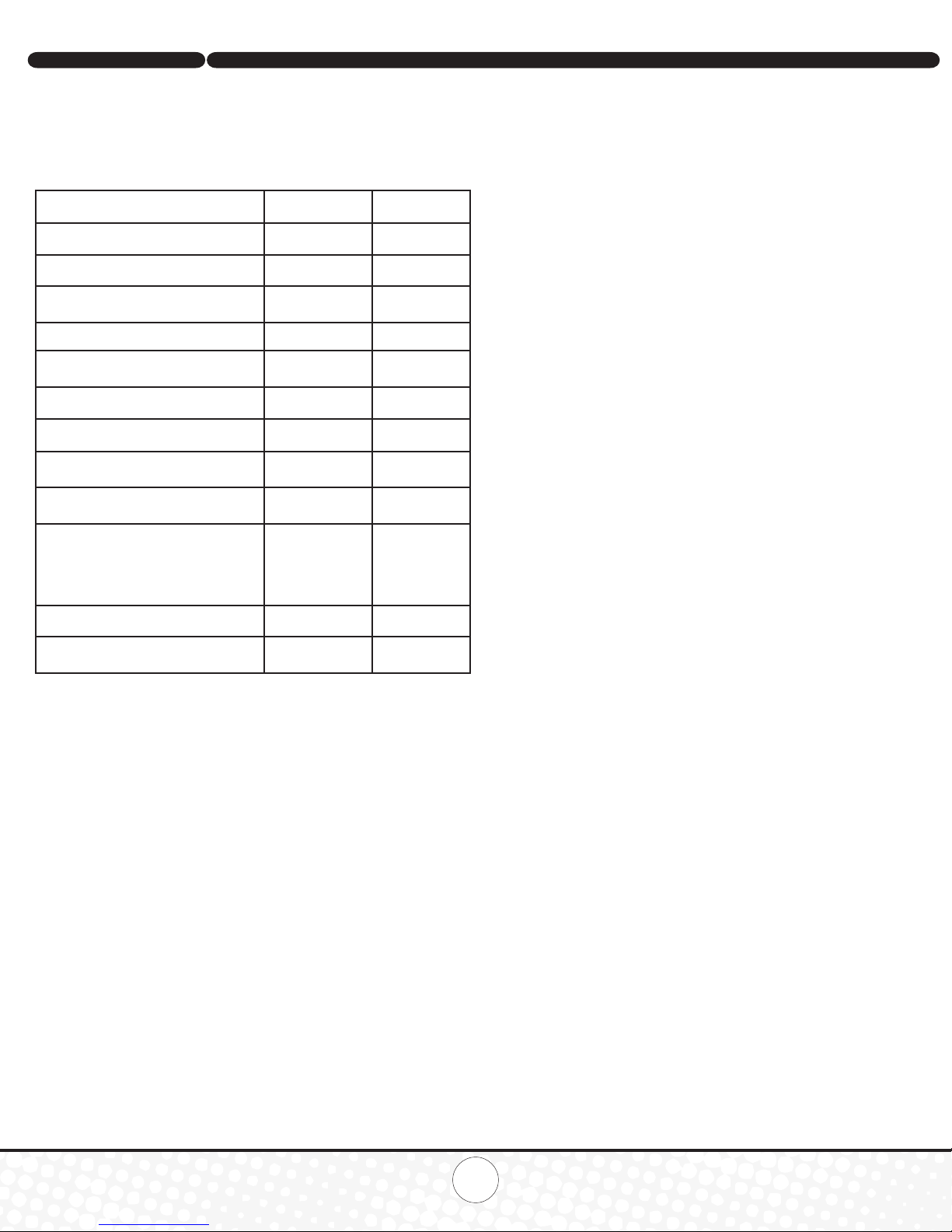
Maintenance Schedule
Latches are located in the back to open the tank for internal maintenance.
To keep machine in good working condition, follow the below
recommended daily and weekly maintenance procedures. Relief valves
should be replaced annually.
Filter Maintenance
All Extractor models have four lters that need to be checked and cleaned
after each week of use. Regular lter maintenance is a simple way to
extend the life of your machines.
Vacuum Stack Filters:
Located inside of the black vacuum tank are two vacuum stacks. Each
stack has one foam lter to help prevent waste material from getting into
the vacuums and cause damage. To maintain these lters:
1. Remove the recovery tank lid.
2. Reach in and pull out the two black lters located in the top of
the vacuum stacks.
3. Clean the lters under a faucet of any debris and check for damage.
If the lters are not damaged, place them back in the stacks. If lters are
damaged and falling apart, replace them.
Pump Filters
The lter is a half-circle shaped screen located on the inside bottom
of the solution tank. To maintain lter:
1. Open solution tank lid.
2. Reach into solution tank and rotate the dome-shaped lter from
its brass nipple by rotating it counter clockwise.
3. Check lter for any debris or damage to screen. Rinse lter of
any debris or replace if damaged.
4. Place new or cleaned lter back onto brass nipple by
rotating it clockwise.
(Additional inline lter inside the machine)
Inline Pump Filter (additional Instructions)
1. Remove the screw that holds the solution tank and the base together
from the front of the machine.
2. Locate the inline lter on the clear solution hose, from the solution
tank to the pump. Take off the clear housing of the lter by turning
it counter clockwise
3. Check lter for any debris or damage to screen. Rinse lter of
any debris or replace if damaged.
4. Place new or cleaned lter back into housing and install housing back
into base by rotating it.
Trouble Shooting
There is no power.
1. Plug power cord(s) in proper outlet(s).
2. If using two cords, make sure each is plugged into a separate circuit.
3. Check circuit breaker and reset if tripped. There should not be any
additional items in use on the same circuit as the machine and the
outlet must be a 20-amp circuit.
Pump does not work properly
1. Snap quick disconnects rmly together.
2. Check solution tank; may be empty.
3. Jets clogged, remove jet and ush clean.
4. Filters clogged, remove lters and rinse clean with water. One lter is
in the bottom of the recovery tank and the secondary lter is located in
the motor area. Be sure to unplug the machine and turn all switches to
the off position prior to cleaning.
5. If brass check valve is stuck, replace valve.
6. Check pump wire. May need to reconnect wire.
7. Switch plate may need to be replaced.
8. If pump motor brushes are worn, replace pump.
Extractor heater does not work properly
1. Check circuit breaker in the building electrical panel.
2. Heating element may need to be replaced.
3. Plug is in a GFI and the GFI is in the off position (popped)
Vacuum motor does not work properly
1. Check that hose is tightly connected.
2. Close drain hose valve completely.
3. Secure the vacuum tank tightly.
4. If water is coming out of the vacuum motor, use a
low foaming detergent.
5. Clean upholstery tool or oor wand jets.
Maintenance item Daily Once a week
Clean and inspect tanks. x
Clean and inspect hoses. x
Check and clean internal lters by twisting off,
rinsing with clean water and replacing. x
Check power supply cable. x
Clean machine with all-purpose cleaner
and cloth. x
Check spray nozzles. x
Flush solution system with x
Remove oat and shut-off screen from
tank and clean. Simply pull off. x
Inspect vacuum hoses for holes and loose
cuffs. x
Inspect spray pattern for clogging. If
clogged, remove spray tips and soak them in
a recommended liquid neutralizer for up to six
hours. To remove spray tip, twist spray tip body
counter-clockwise.
x
Lubricate wheels with water resistant oil. x
Inspect machine for water leaks and loose
hardware. x