GUIDEBOOK for
Technical Partners
3
Guidebook for Technical Partners - All rights reserved, EyeClick Ltd
Ver 1.04 –August 6, 2015
Contents
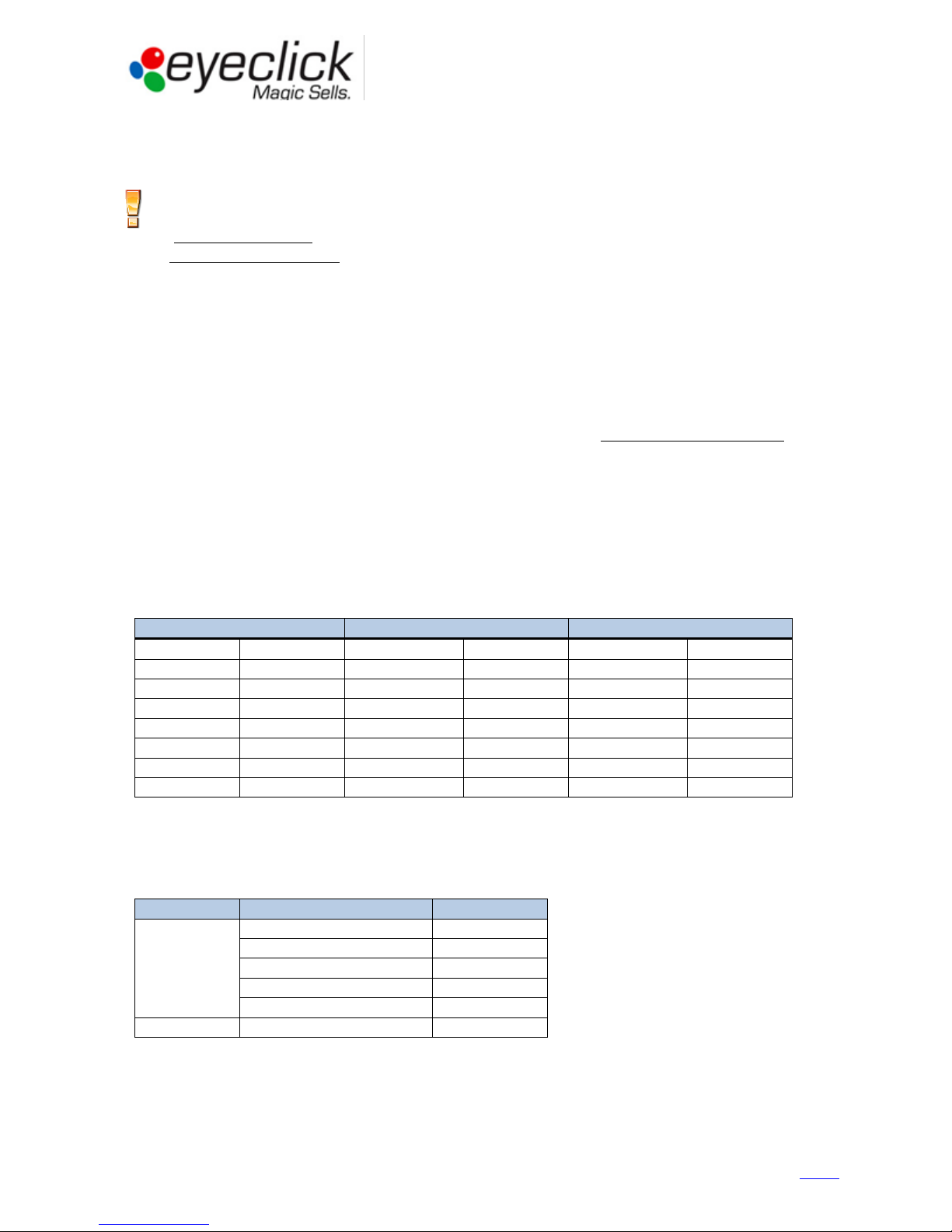
Table of Contents
Table of Contents ...........................................................................................................................3
Introduction ...................................................................................................................................4
General ..................................................................................................................................................................4
Operations Workflow ............................................................................................................................................5
EyePlay device description..............................................................................................................6
Device overview and dimensions ..........................................................................................................................6
Device components ...............................................................................................................................................7
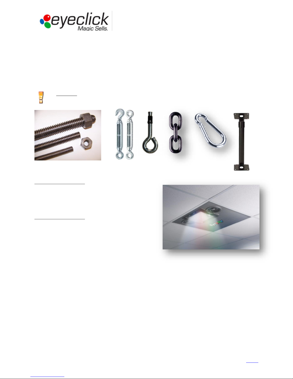
EyePlay device installation..............................................................................................................9
Working conditions................................................................................................................................................9
Choosing installation spot .....................................................................................................................................9
Preparing the device for installation ...................................................................................................................10
Installing EyePlay Device......................................................................................................................................11
Powering up, adjusting and calibrating ...............................................................................................................14
Basic Operation Instructions .........................................................................................................16
Reviewing the License Tab...................................................................................................................................17
Setting the Display Tab ........................................................................................................................................17
Projector configuration........................................................................................................................................19
Configuring Games in the Applications Tab (floor/wall units).............................................................................20
Using the Events Mode (floor/wall units)............................................................................................................21
Keyboard Controls ...............................................................................................................................................22
Table Menu (table units only)..............................................................................................................................22
Quick Reference guide.........................................................................................................................................22
Technician access .........................................................................................................................23
Eyeclick Toolbar ...................................................................................................................................................23
Shutting Down .....................................................................................................................................................24
Technical support and stock management.....................................................................................25
Technical Support Workflow ...............................................................................................................................25
Support Contact details .......................................................................................................................................26
EyeClick Knowledge base.....................................................................................................................................26
On-site support visits...........................................................................................................................................26
Lamp replacement...............................................................................................................................................27
Projector replacement.........................................................................................................................................28
Computer replacement .......................................................................................................................................29
Remote controller and keyboard.........................................................................................................................29
Handling faulty equipment - RMA .......................................................................................................................30
Shared database ..................................................................................................................................................31
Troubleshooting...................................................................................................................................................32
Billing and Invoicing......................................................................................................................33
Annexes .......................................................................................................................................34
Annex A: Pre-installation requisites (to be filled by client) .................................................................................35
Annex B: Site Survey Form (To be filled by Installer, or client in special cases) ..................................................36
Annex C: Installation Report (To be filled by Installer) ........................................................................................38
Annex D: Client Acceptance Form (To be filled by client)....................................................................................39
Annex E: Technical on-site service report (To be filled by technician) ................................................................40