Denali 66’’ & 72’’ Plow
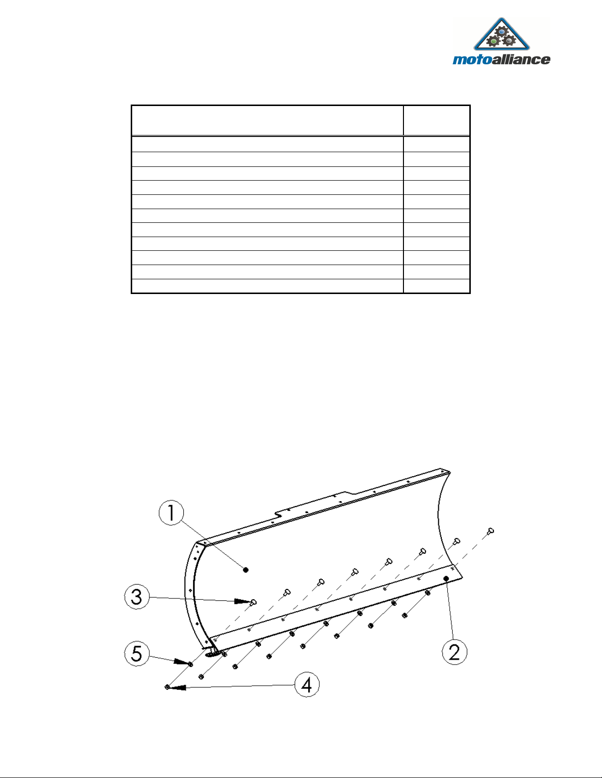
Blade & Pushtube Assembly
23001
Industrial Blvd Rogers, MN 55374
Pushtube Assembly Hardware List
Verify that your Pushtube box includes the following hardware.
ITEM
NO.
Part Description Quantity Reorder
SKU
12 1/4''-20 x 1.5'' Hex Head olt 1 -
13 1/4''-20 Nylock Nut 1 -
14 1/4'' Flat Washer 2 -
15 1/4'' ID Aluminum Spacer 1 -
16 3/8''-16 x 1'' Hex Head olt 11 -
17 3/8'' Flat Washer 17 -
18 3/8''-16 Nylock Nut 2 -
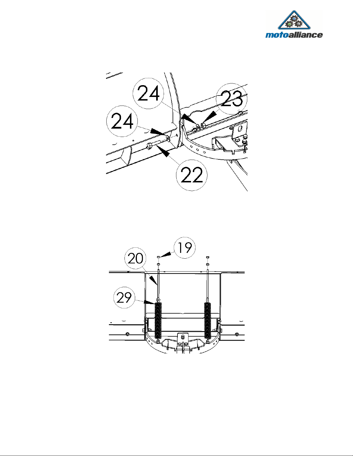
19 3/8''-16 Regular Nut 4 -
20 3/8''-16 x 8'' Eye olt 2
21 3/8''-16 x 1.5'' Hex Head olt 2 -
22 1/2''-13 x 2'' Hex Head olt 2 -
23 1/2''-13 Nylock Nut 2 -
24 1/2'' Flat Washer 4 -
25 5/8''-11 x 2'' Hex Head olt 1 -
26 5/8''-11 Nylock Nut 1 -
27 5/8'' Flat Washer 1 -
28 5/8'' ID Step Spacer 1 -
29 10'' Extension Spring 2
30 Lock Lever Spring 1
31 Stop lock 2
32 Quick Release Pin 2
33 Quick Release Pin Washer 2
34 Pivot Lever Support racket 1
35 Pivot Lever Riser 2
36 Pivot Lock Lever 1
37 Winch Attachment racket 1
38 0.030 spacer for 5/8’’ ID Step 1
Figure 5