GV47001b_e.doc / Feb-08 Page 5 / 9
2. Electrical Connections and LEDs
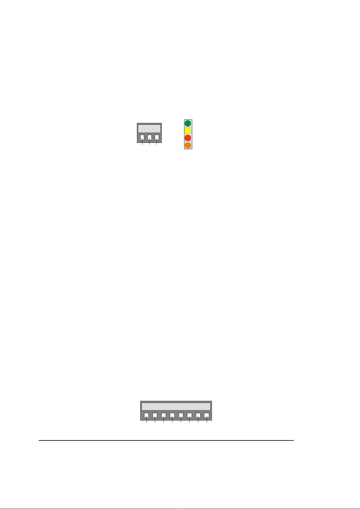
2.1. Power Supply and LED Assignment
The unit provides a 3-position screw terminal strip for supply from a 10 – 30 volts DC power
unit. The current consumption is approx. 100 mA (no-load operation).
The “Select” input terminal provides selection of the desired source encoder. Details will be
described later.
The upper LED (green) signals that power is applied to the unit.
The lower LEDs (yellow, red, orange) signal the actual logical states of the input channels A, B
and Z. With very low input frequencies it is possible to visually check the input pulses, the
phase displacement A/B and the index pulse function of an encoder.
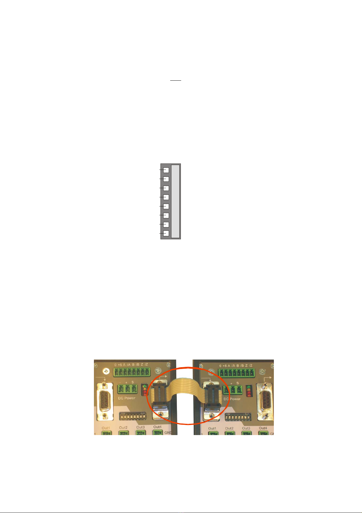
2.2. Encoder Input
The signal to be distributed to the outputs must be applied to the 8-position input terminal. The
appropriate input level (RS422 or HTL 10-30 V) must be set to the DIL switches correspondingly.
With RS422 setting, and also with HTL setting and impulse levels lower than 15 volts, the unit
needs at any time the non-inverted and the inverted input signals (differential input).
With HTL levels higher than 15 volts you are free to either use the inverted inputs or to just
leave them unconnected (the unit will accept differential and single-ended operation as well
with input levels >15 volts).
Other input characteristics like TTL-single-ended inputs or Namur signals are possible as well,
but may need additional remote circuit at the input terminals.
Where the potential-separation between input and outputs is required, the input encoder must
be supplied from a remote power source.
The DIL switch allows to connect the unit’s internal power supply (approx. 5.3 volts) to the
terminals „0“ und „+5“ for use as an auxiliary encoder supply. However, this will switch off the
potential separation and tie the encoder potential to the general GND.
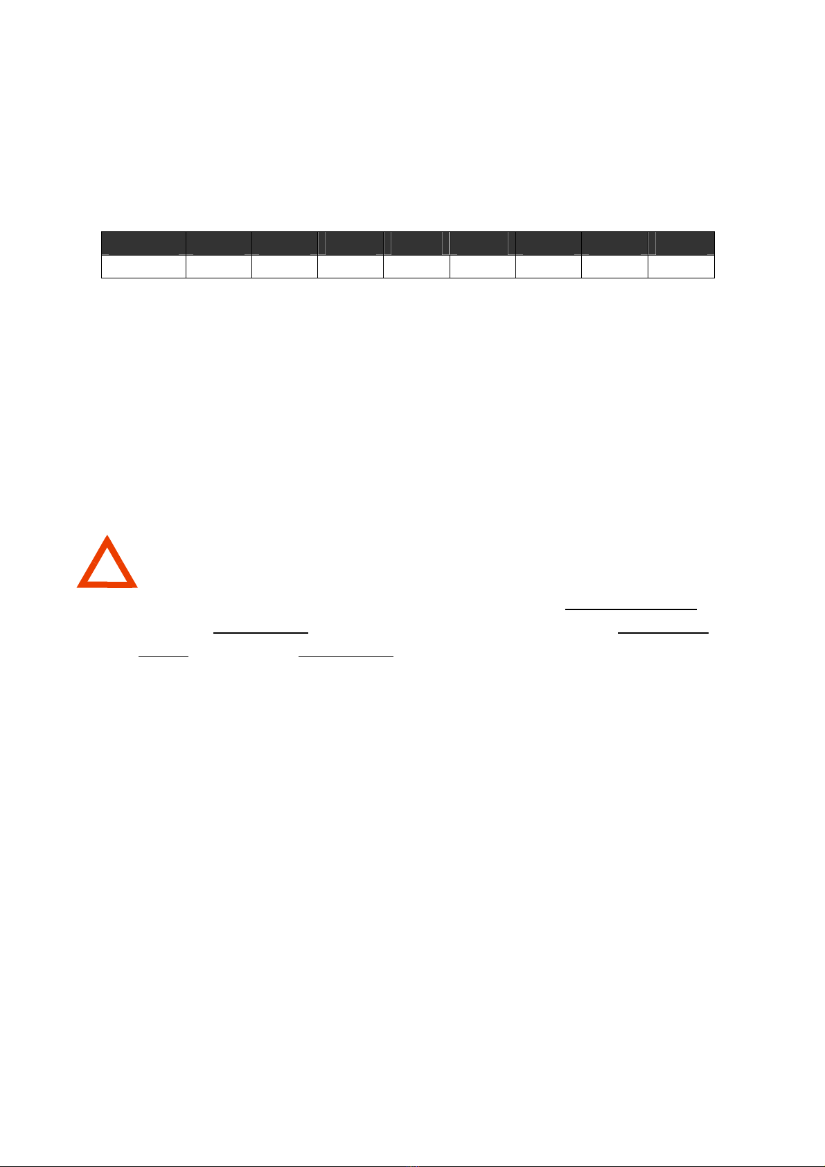
Input terminal strip:
A codification of the input connector avoids accidentally mix-up with other connectors.
-+
Select
1 2 3
ON
A
B
Z
0+
B
BZ
1 2 3 4 5 6 7 8