Motrona GS202 User manual

Gs202_01c_oi_e.doc / Nov-15
GS202
Encoder Switch
20:2 encoder switch
20 encoder inputs (TTL / RS422 standard)
Input signals A, /A, B, /B, Z, /Z on each encoder input
2 x 6 control inputs (HTL / PNP)
2 encoder outputs (TTL / RS422 standard)
Input frequency max. 1 MHz
Latency period < 250 ns
Channel switching < 1 ms
Operating Instructions

Gs202_01c_oi_e.doc / Nov-15 Page 2 / 12
Safety Instructions
This manual is an essential part of the unit and contains important hints about function,
correct handling and commissioning. Non-observance can result in damage to the unit
or the machine or even in injury to persons using the equipment!
The unit must only be installed, connected and activated by a qualified electrician
It is a must to observe all general and also all country-specific and application-specific
safety standards
When this unit is used with applications where failure or maloperation could cause
damage to a machine or hazard to the operating staff, it is indispensable to meet
effective precautions in order to avoid such consequences
Regarding installation, wiring, environmental conditions, screening of cables and
earthing, you must follow the general standards of industrial automation industry
–Errors and omissions excepted –
By using this device, ESD protection measures must be complied.
General instructions for cabling, screening and grounding can be found
in the SUPPORT section of our website http://www.motrona.com
Version:
Description:
GS20201a_sn/nw_05/14
First edition
GS20201b_sn/sk_10/14
design adaption, technical additions
Gs202_01c_oi/Oct-15/ag
Notice about ESD measures (see above)

Gs202_01c_oi_e.doc / Nov-15 Page 3 / 12
Table of Contents
1. Functional Description .................................................................................................. 4
2. Electrical Connection .................................................................................................... 5
2.1. Power Supply ...................................................................................................................5
2.1.1. Encoder Supply................................................................................................................5
2.2. Pulse Inputs IN 1 –20......................................................................................................6
2.3. Control Inputs...................................................................................................................7
2.3.1. External wiring of the control inputs..............................................................................8
2.4. Pulse Outputs OUT 1 –2..................................................................................................9
3. Status Display............................................................................................................. 10
3.1. Example for status display.............................................................................................10
4. Technical Specifications ............................................................................................. 11
4.1. Dimensions ....................................................................................................................12

Gs202_01c_oi_e.doc / Nov-15 Page 4 / 12
1. Functional Description
The GS202 is an Encoder Switch with 20 encoder inputs, 2 encoder outputs and 2 x 6 control
inputs. Depending on the configuration of the control inputs, the device switches thorugh the
signal on the input (IN 1 –20) to the corresponding output (OUT 1 –2).
Both outputs operate independently of each other. The output has to be configurated via the
corresponding control input. To each output only one of the 20 inputs can be allocated.
Via a 5-bit parallel signal (BIT 0 –BIT 4) a special input (e. g. IN 16) will be selected. This input
will be assigned to the output (e. g. OUT 2) by a pulse on terminal SET.
If the bit pattern is 00000 or in case of an invalid 5-bit-parallel signal, no input will be assigned
to the output. During this process all tracks (A, B, Z) of the output are set to LOW and all
inverted tracks (/A, /B, /Z) are set to HIGH.
Illuminated LEDs indicate the respective input assignment. Green LEDs signalize output OUT 1,
yellow LEDs signalize output OUT 2.

Gs202_01c_oi_e.doc / Nov-15 Page 5 / 12
2. Electrical Connection
+V
GND
+V
IN 1 2 3 4 5 6 8 97
IN 11 12 13 14 15 16 18 1917 20
10
OUT 1 OUT 2
GND
BIT 4
BIT 3
BIT 2
BIT 1
BIT 0
SET
GND
7654321 8
32
1
IN
AUX
GND
BIT 4
BIT 3
BIT 2
BIT 1
BIT 0
SET
GND
7654321 8
Voltage and encoder supply:
Pin
Type
Function
01
GND
Minus pole of the power supply, reference potential
02
+V IN
Plus pole of the power supply
03
+V AUX
Input for the encoder supply
2.1. Power Supply
The device can be supplied by GND / +VIN on the 3-pin terminal with a DC voltage of
18 –35 VDC. The power supply has a reverse polarity protection. The current consumption
depends on the level of the input voltage and the internal load condition of the unit. With a
voltage supply of 24 VDC and unwired in- and outputs, the current consumption is about 30 mA.
2.1.1. Encoder Supply
Via +VAUX on the 3-pin terminal an encoder supply of 5 –35 VDC can be fed in. This supply is
available on each of the 20 inputs (9-pin Sub-D male connector) of Pin 4.
Gs202_01c_oi_e.doc / Nov-15 Page 6 / 12
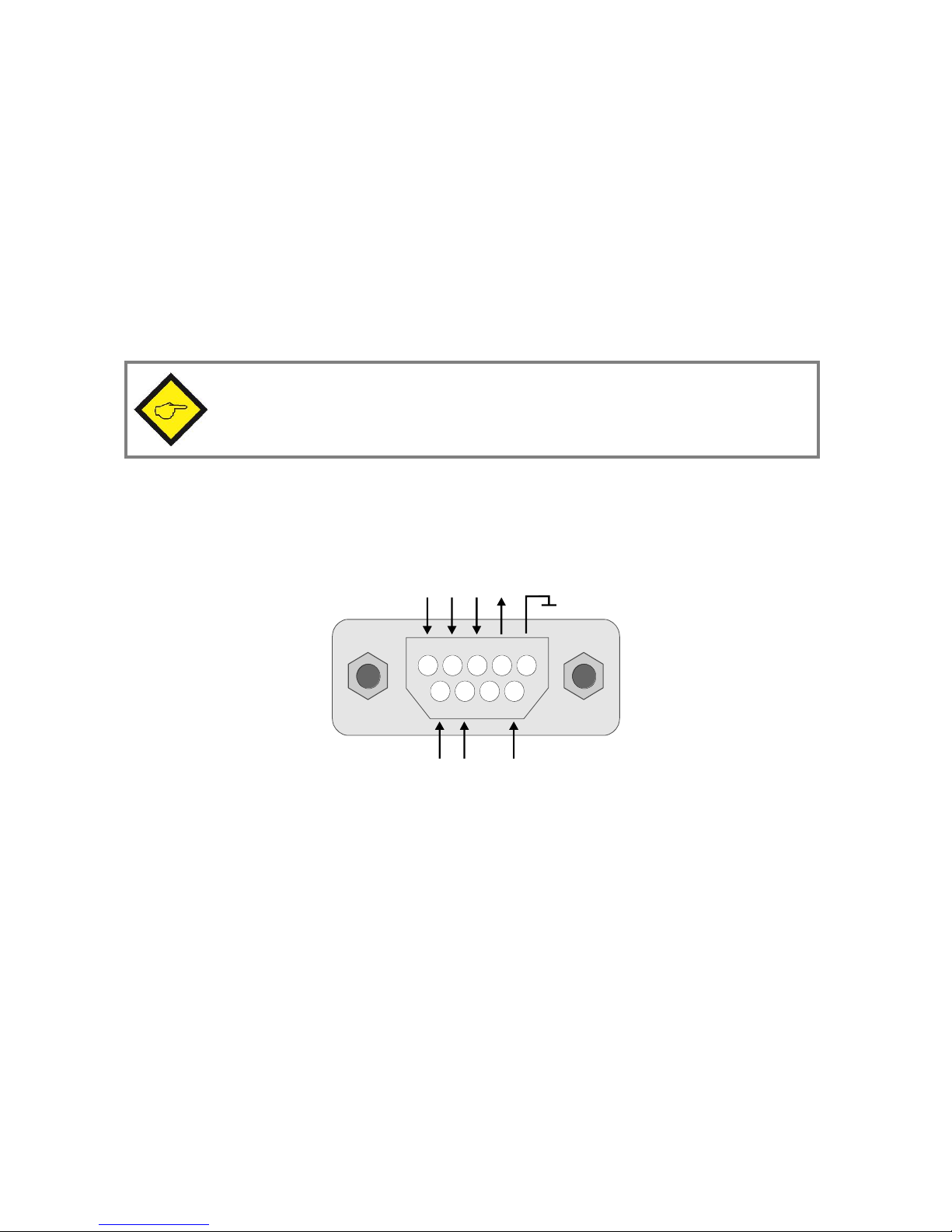
2.2. Pulse Inputs IN 1 –20
There are 20 incremental inputs for differential / symmetric encoder signals (TTL / RS422
standard). The encoders / sensors can be connected to the desired input witn 9-pin Sub-D male
connector.
These devices accept single channel symmetrical input signals (A and /A only, no information
on the direction of rotation) as well as dual channels (also channel B and /B, recognition of
direction of rotation). If necessary, also the zero pulses Z and /Z of the respective encoder can
be connected. The maximum input frequency is 1 MHz.
It is imperative to ensure that the inverted signal /A, /B or /Z is also connected.
GND
1 2 3 4 5
986 7
A
/A
B
VAUX
Input IN 1 - 20
9-pin Sub-D male connector
/B
Z
/Z

Gs202_01c_oi_e.doc / Nov-15 Page 7 / 12
2.3. Control Inputs
Depending on the connection of the control inputs, one input can be assigned to the output. Via
BIT 0 –BIT 4 one input is selected (see 2.3.1 External wiring of the control inputs). Only by an
impulse on the terminal SET activates the selection. To each output only one of the 20 inputs can
be allocated. The minimum pulse duration on the control inputs is 1 ms. The control inputs operate
with HTL-level 10 –30 VDC (PNP, switch to +).
Control Inputs for OUT 1 / OUT 2:
Pin
Type
Function
01
GND
Minus pole of the power supply, reference potential
02
SET
Input for SET impulse
03
BIT 0
Input for BIT 0
04
BIT 1
Input for BIT 1
05
BIT 2
Input for BIT 2
06
BIT 3
Input for BIT 3
07
BIT 4
Input for BIT 4
08
GND
Minus pole of the power supply, reference potential
Input wiring SET and BIT 0 –4:
Timing diagramm:
HTL / PNP, LOW < 2,5V, HIGH > 10V
GND
SET
BIT 0
BIT 1
BIT 2
BIT 3
BIT 4
GND
7654
3
28
1 ms
1 ms
BIT 0 - 4
SET
1 ms
1 ms 1 ms
Read in
1 ms

Gs202_01c_oi_e.doc / Nov-15 Page 8 / 12
2.3.1. External wiring of the control inputs
Bit 4
Bit 3
Bit 2
Bit 1
Bit 0
Input to Output x
0
0
0
0
0
no allocation
0
0
0
0
1
Input 1 to Output x
0
0
0
1
0
Input 2 to Output x
0
0
0
1
1
Input 3 to Output x
0
0
1
0
0
Input 4 to Output x
0
0
1
0
1
Input 5 to Output x
0
0
1
1
0
Input 6 to Output x
0
0
1
1
1
Input 7 to Output x
0
1
0
0
0
Input 8 to Output x
0
1
0
0
1
Input 9 to Output x
0
1
0
1
0
Input 10 to Output x
0
1
0
1
1
Input 11 to Output x
0
1
1
0
0
Input 12 to Output x
0
1
1
0
1
Input 13 to Output x
0
1
1
1
0
Input 14 to Output x
0
1
1
1
1
Input 15 to Output x
1
0
0
0
0
Input 16 to Output x
1
0
0
0
1
Input 17 to Output x
1
0
0
1
0
Input 18 to Output x
1
0
0
1
1
Input 19 to Output x
1
0
1
0
0
Input 20 to Output x
1
0
1
0
1
no allocation
1
0
1
1
0
no allocation
1
0
1
1
1
no allocation
1
1
0
0
0
no allocation
1
1
0
0
1
no allocation
1
1
0
1
0
no allocation
1
1
0
1
1
no allocation
1
1
1
0
0
no allocation
1
1
1
0
1
no allocation
1
1
1
1
0
no allocation
1
1
1
1
1
no allocation
If the bit pattern is 00000 or in case of an invalid 5-bit-parallel signal, no input will be assigned
to the output. During this process all tracks (A, B, Z) of the output are set to LOW and all
inverted inputs (/A, /B, /Z) are set to HIGH.
Gs202_01c_oi_e.doc / Nov-15 Page 9 / 12
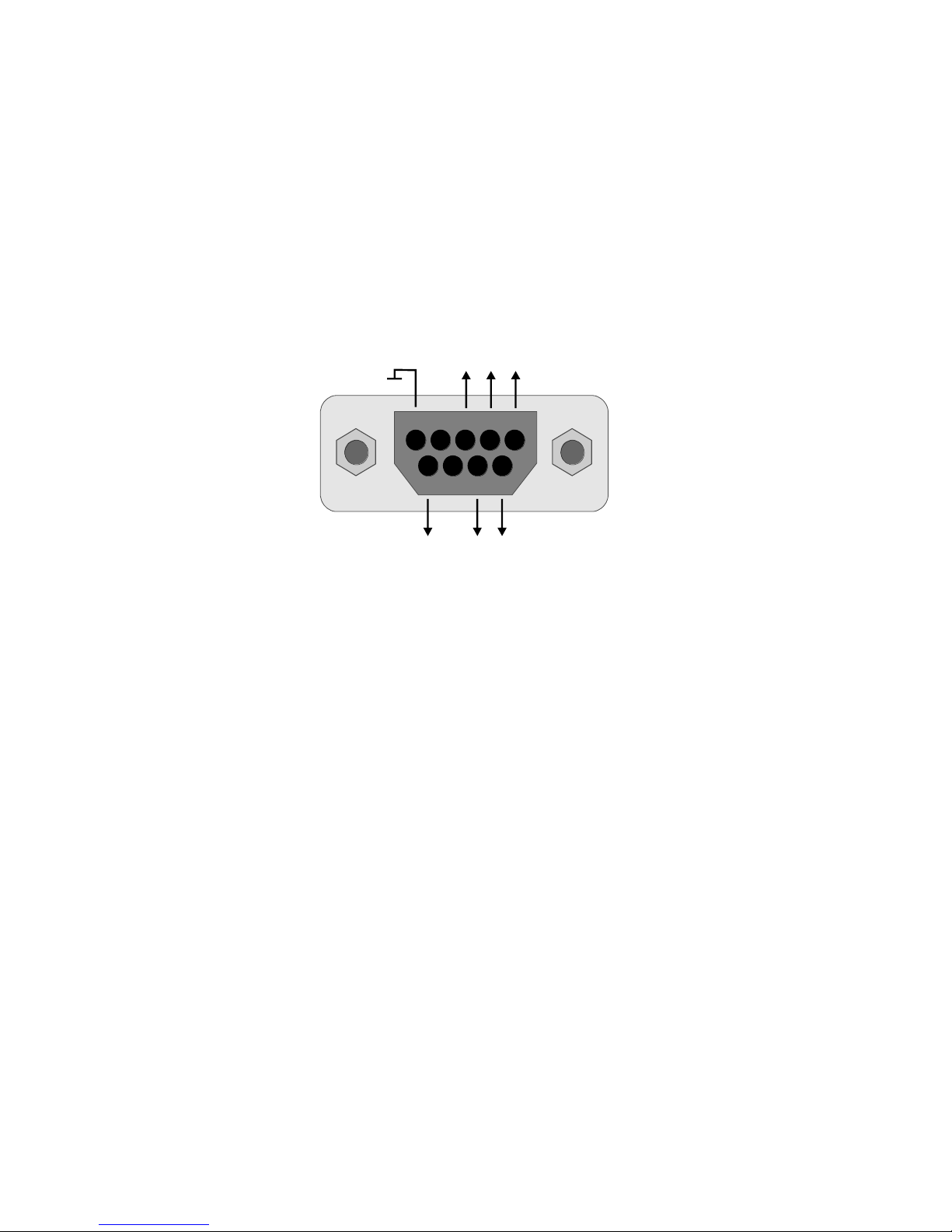
2.4. Pulse Outputs OUT 1 –2
Two outputs are available (each with 9-pin Sub-D female connector, OUT 1 –2). Depending on
the connection of the control inputs, they switch the signal of one input (IN 1 –20) to the
corresponding output (OUT 1 –2).
The outputs operate in RS422 standard with differential / symmetric signals.
GND
A
/A
B
Output OUT 1 - 2
9-pin Sub-D female connector
/B
Z
/Z
1234
5
9 8 67

Gs202_01c_oi_e.doc / Nov-15 Page 10 / 12
3. Status Display
The device features 42 status LEDs:
a green LED directly to the left of OUT 1
(Status: OUT 1 ready for operation)
a yellow LED directly to the right of OUT 2
(Status: OUT 2 ready for operation)
a green and a yellow LED, directly to the left and the right of each input
(Status green: Input connected with OUT 1)
(Status yellow: Input connected with OUT 2)
3.1. Example for status display
+V
GND
+V
IN 1 2 3 4 5 6 8 97
IN 11 12 13 14 15 16 18 1917 20
10
OUT 1 OUT 2
GND
BIT 4
BIT 3
BIT 2
BIT 1
BIT 0
SET
GND
7654321 8
32
1
IN
AUX
GND
BIT 4
BIT 3
BIT 2
BIT 1
BIT 0
SET
GND
7654321 8
Example: OUT 1 ready for operation and pass through the signals of IN 16
OUT 2 ready for operation and pass through the signals of IN 2

Gs202_01c_oi_e.doc / Nov-15 Page 11 / 12
4. Technical Specifications
Power supply:
17 to 30 VDC
Residual ripple:
≤10 % @ 24 VDC
Current consumption:
Approx. 30 mA @ 24 VDC (unwired)
Encoder supply:
5 to 35 VDC (connect to +VAUX )
Control inputs:
HTL (PNP)
LOW < 2,5 V
HIGH > 10 V (max. 35 V)
Pulse width > 1 ms
Ri > 10 kOhm
Pulse input:
Differential / symmetrical pulse inputs (A, /A, B, /B, Z, /Z)
RS422, termination resistor 500 Ohm (intern) on each channel
Input frequency:
Max. 1 MHz
Pulse output:
RS422 (A, /A, B, /B, Z, /Z)
Output frequency:
Max. 1 MHz
Latent periode:
< 250 ns
Channel switch-over:
< 1ms
Connection terminals:
Power supply:
screw terminal, 3-pin, wire cross section max. 1.5 mm²
Control inputs:
screw terminal 2 x 8-pin, wire cross section max. 1 mm²
Plug / socket:
Pulse inputs:
20 x 9-pin Sub-D male connector
Pulse outputs:
2 x 9-pin Sub-D female connector
Display:
2 LEDs (yellow/green) on each input
1 LED (yellow/green) on each output
Housing:
Plastic housing grey/black, for mounting to standard DIN rails
(35 mm C-profile)
Weight:
Approx. 530 g
Protection:
IP20
Ambient temperature:
Operation: 0 to +60°C
Storage: -25 to +70°C
Conformity and standards:
EN 61326-1:2006
EN 61000-6-2:2006-03
EN 61000-6-3:2007-09
Gs202_01c_oi_e.doc / Nov-15 Page 12 / 12
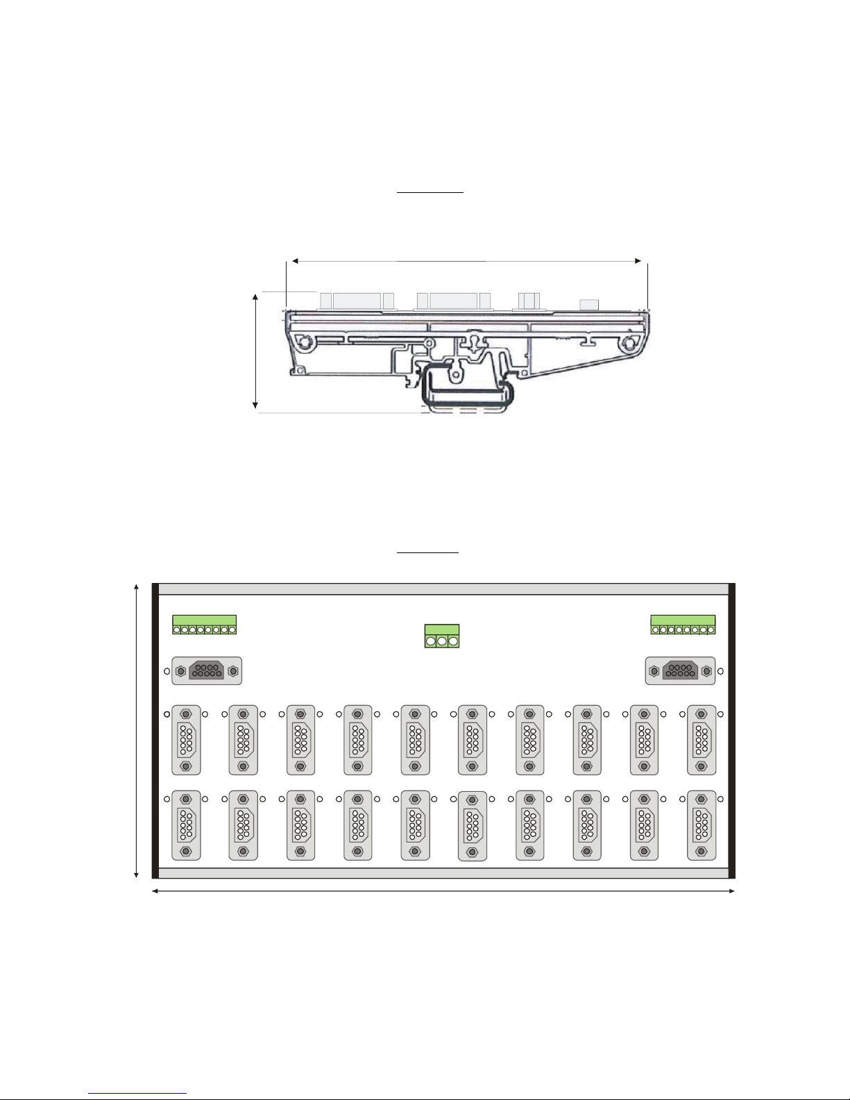
14,2 cm
4,6 cm
4.1. Dimensions
Side view:
Top view:
+V
GND
+V
IN 1 2 3 4 5 6 8 97
IN 11 12 13 14 15 16 18 19
17 20
10
OUT 1 OUT 2
GND
BIT 4
BIT 3
BIT 2
BIT 1
BIT 0
SET
GND
7
6
54
321 8
321
IN
AUX
GND
BIT 4
BIT 3
BIT 2
BIT 1
BIT 0
SET
GND
7654
321 8
27 cm
14,2 cm
Table of contents
Other Motrona Switch manuals


Popular Switch manuals by other brands


SignaMax
SignaMax FO-065-7110 Series user guide

Openpath
Openpath Core Series installation guide

Moxa Technologies
Moxa Technologies TN-4516A non-PoE series Quick installation guide

Asus
Asus GigaX 1016 user guide

Bluestream
Bluestream SW41HDBT user manual

Accton Technology
Accton Technology Classic-2040 Quick installation guide


