Motrona GV155 User manual

control – motion – interface
motrona GmbH
Zwischen den Wegen 32
78239 Rielasingen - Germany
Tel. +49 (0)7731-9332-0
Fax +49 (0)7731-9332-30
www.motrona.com
GV15502B_e.DOC / Mrz-08 Page 1 / 9
GV155, GV156
Electronic Cross Switchers for Encoder Signals
and Analogue Signals
•2 x 2 Cross matrix switch for encoders RS422 (A, /A, B, /B, Z, /Z) or HTL 15-30V
•2 x 2 Cross matrix switch for analogue signals +/- 10V
•Cascadable inputs and outputs
•Bounce-free electronic switching of all channels
•PLC compatible control inputs for source-to-target selection, signals inversion, line
inhibit and for/rev selection
•Closed 19“ aluminum housing, 14TE wide and 3HE high.
Front connection via standard Sub-D-connectors
•Supply range 18...30VDC
•Also suitable for DIN rail mounting with option “SM150”
Operating Instructions

GV15502B_e.DOC / Mrz-08 Page 2 / 9
Safety Instructions
•This manual is an essential part of the unit and contains important hints about
function, correct handling and commissioning. Non-observance can result in
damage to the unit or the machine or even in injury to persons using the
equipment!
•The unit must only be installed, connected and activated by a qualified electrician
•It is a must to observe all general and also all country-specific and application-
specific safety standards
•When this unit is used with applications where failure or maloperation could cause
damage to a machine or hazard to the operating staff, it is indispensable to meet
effective precautions in order to avoid such consequences
•Regarding installation, wiring, environmental conditions, screening of cables and
earthing, you must follow the general standards of industrial automation industry
•- Errors and omissions excepted –
Version: Description:
GV15502B/ TJ/ Sep 03/ P1...7,2 GV155-1 renamed to GV156 Block diagram revised

GV15502B_e.DOC / Mrz-08 Page 3 / 9
Table of Contents
1. Block Diagram.................................................................................................4
2. Applications....................................................................................................5
3. Connecting Diagrams......................................................................................6
3.1. Encoder inputs GV155 and GV156 with TTL level.................................................6
3.2. Encoder inputs GV156 with HTL level (Option HTLIN1) ........................................6
3.3. Encoder outputs GV155 and GV156 ......................................................................6
3.4. Analogue inputs and outputs ................................................................................6
3.5. Control inputs ........................................................................................................7
4. Output Level Selection (GV156 only) ..............................................................7
5. Technical Specifications.................................................................................8
6. Dimensions .....................................................................................................9
GV15502B_e.DOC / Mrz-08 Page 4 / 9
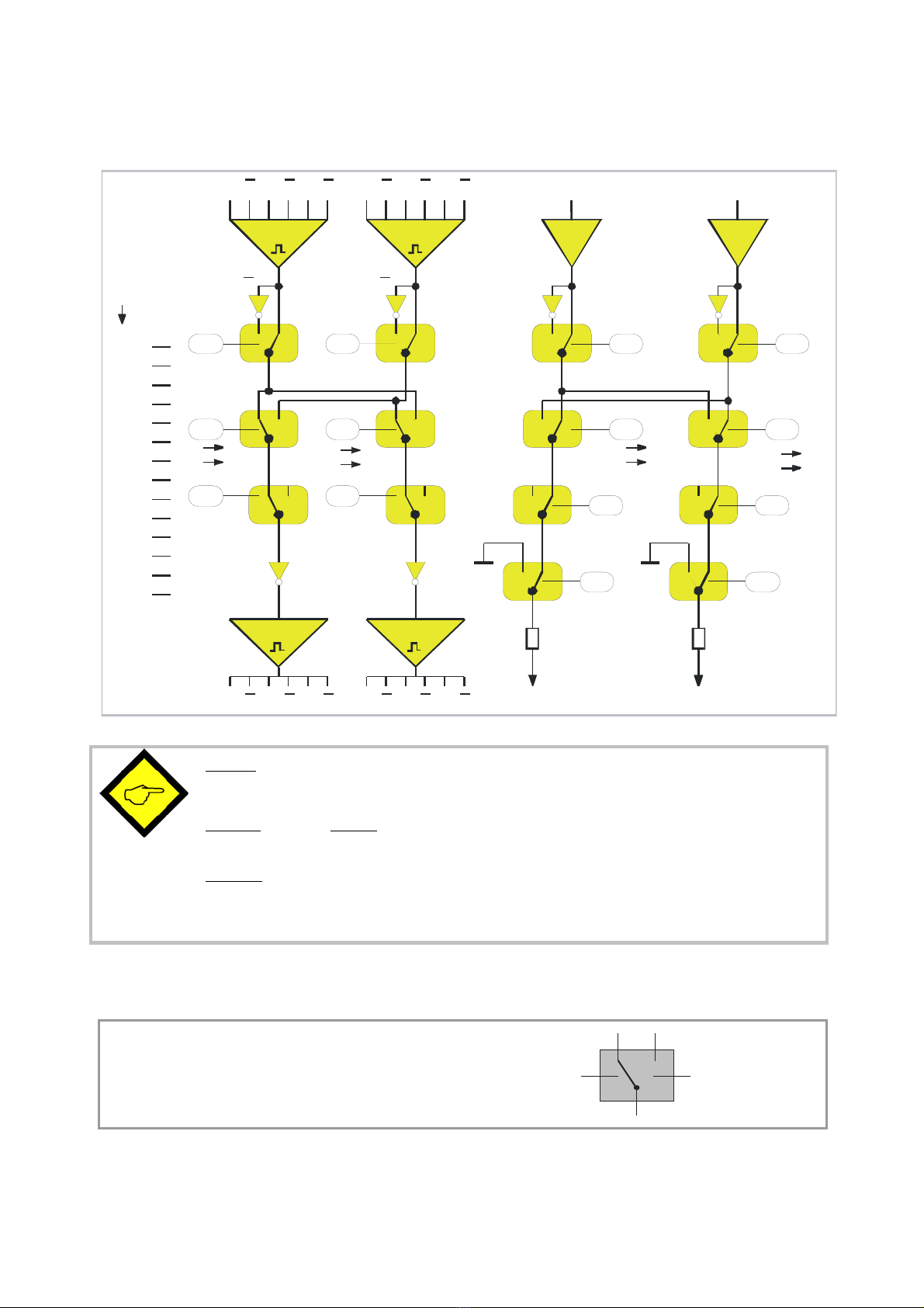
1. Block Diagram
C2
AABBZZ AABBZZ
C5
C1
C3 C6
C4
C8 C12
C7
C9
C10
C11
C13
C14
GND GND
AABBZZAABBZZ
NC NC NC NC
+/- 10V+/- 10V
IN 1 IN 2
OUT 1 OUT 2
Control
C1
C2
C3
C4
C5
C6
C7
C8
C9
C10
C12
C11
C13
C14
2
+/- 10V +/- 10V
ANA OUT
22
12
Rev/For Rev/For
ON/OFF ON/OFF
DIR/Inv DIR/Inv
ON/OFF
Line/GND
ON/OFF
Line/GND
11
21 22
12 1 1
21
**
**
ANA
IN1 ANA
IN2
A, A A, A
1
300R 300R
GV155:All encoder inputs and outputs are designed for TTL level
(RS422 line driver signals).
GV156: Encoder inputs are available with TTL/RS422 format (standard) or with
HTL (15-30V) format against ordering information “Option HTLIN1”. Encoder
outputs are individually adjustable to either TTL/RS422 level or HTL (15-30V)
level by DIL switch setting.
*) Only with model GV155 but not with model GV156
The signal ways shown in the block diagram correspond to all control inputs in LOW or
unconnected state
High-stateLow-state
(N.C.) (N.O.)
Low = 0...5V, High = 15...30V
Control Input definition:

GV15502B_e.DOC / Mrz-08 Page 5 / 9
2. Applications
Typical applications can be found in drive technology and general automation, where impulse
signals or analogue control lines have to be commutated between several peripheral sources
and target units.
A relays circuit basically could do the same, but can become costly and also unreliable in
operation, by contact overlapping, bouncing and general problems with switching of small scale
signals, micro currents and high frequencies. Often, there are also unacceptable screening and
wiring problems when using relays.
Use of GV155 or GV156 avoids any of these problems and allows proper and reliable switching
of digital and analogue signals. There are 14 control inputs C1…C14 that can operate from
mechanical switches or under PLC control.
Application Example:
Some times, in applications with electronic synchronizing of drives, there are two master drives
that need to be synchronized by turns with only one slave drive, depending on the actual
production. The subsequent schematic shows how to solve the analogue and digital signal
commutation required:
Master1 Master2 Slave
Synchroniser
GV 155
0-10 V
0-10V
MMM
0-10V
Control
0-10V

GV15502B_e.DOC / Mrz-08 Page 6 / 9
3. Connecting Diagrams
3.1. Encoder inputs GV155 and GV156 with TTL level
GND
12 3 4 5
9
8
67
Encoder input 1
B/
A
A
+5,5Vout
/N N /B
Both connectors: Sub-D-9, male on unit site
GND
12 34 5
9
8
67
Encoder input 2
B
/A
A
+5,5Vout
/N N /B
3.2. Encoder inputs GV156 with HTL level (Option HTLIN1)
GND
12 3 4 5
9
8
67
Encoder input 1
B
A
+24Vout
N
Both connectors: Sub-D-9, male on unit site
GND
12 34 5
9
8
67
Encoder input 2
B
A
+24Vout
N
3.3. Encoder outputs GV155 and GV156
GND
124
598 67
B/
A
A
/B N /N
GND
1234
598 67
B/
A
A
/B N /N
Encoder Output 1
Both connectors: Sub-D-9, female on unit site
Encoder Output 2
Output levels:
GV155: TTL/ RS422 always
GV156: TTL or HTL, depending on DILswitch settings
3.4. Analogue inputs and outputs
GND 12 3 4 5
9
8
67
(+/-10V)
+12V
IN1 IN2 -12V
Analogue Inputs: Sub-D-9, male on unit
1234
598 67
-12V OUT2 OUT1
Analogue Outputs: Sub-D-9, female on unit
(+/-10V)
+12V
GND
GV15502B_e.DOC / Mrz-08 Page 7 / 9
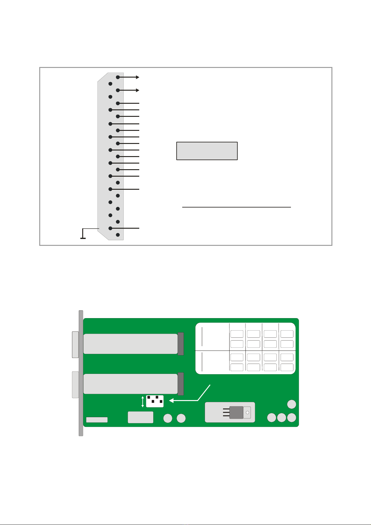
3.5. Control inputs
+24VDC out
1
14
C1
2
15
C2
3
C3*
16
C6*
4
C4
17
C10
5
18 6
19 7
20 8
21 9
22 10
23 11
24 12
25 13
C5
C14
C9
C7
C13
C8
C11
C12
GND
Control Inputs:
*)Only with GV155, but not with GV156
Low
High =
=0...5 V
15...30 V
Sub-D-25 male on unit site
4. Output Level Selection (GV156 only)
To select the desired output level, please remove the right-hand side plate and set the DIL
switch according to need:
Flachband-Kabel
Ribbon cable
Flachband-Kabel
Ribbon cable
1 2 3 4
ON
OFF
DIL-switch
Output1
TTL (5V):
1234
HTL (24V):
Output2
TTL (5V):
HTL (24V):
OFF
OFF
OFF
OFF
ON
ON
ON
ON
xx
xx
xx
xx

GV15502B_e.DOC / Mrz-08 Page 8 / 9
5. Technical Specifications
Power supply : 18...30 V DC/ 300 mA
Max. encoder frequency : 400 kHz (GV155), 300 kHz (GV156)
Encoder propagation delay : 200 ns (GV155), 700 ns (GV156)
Encoder Inputs : RS422, 5V / 10 mA (TTL)
15 –30 V / 10 mA / PNP (Option HTLIN1)
Encoder Outputs : RS422, 5V / 20 mA (GV155)
5V / 24V / 50 mA (GV156)
Analogue inputs : +/- 10V, RIN = 100 kΩ
Analogue Outputs : +/- 10V, ROUT = 300 Ω
Analogue accuracy : 0.05 %
Analogue Offset drift : 0.3 mV
Control Inputs : Low = 0...5V (or unconnected)
High = 15...30V (PNP)
Switch-over time : typical 200 ns
Dimensions : see drawing
Operating temperature range : 0…45 º (32 ... 113°F)
Weight : approx. 650 g
Conformity and standards : EMC 89/336/EEC: EN 61000-6-2
EN 61000-6-3
LV73/23/EEC: EN 61010-1

GV15502B_e.DOC / Mrz-08 Page 9 / 9
6. Dimensions
122,5
129 111
70
7
11
70,5
171
188
197
55,5
70,5
4570
Vorderansicht Seitenansicht
Rückansicht
Draufsicht
Rear view
Front view Side view
Top view
This manual suits for next models
1
Table of contents
Other Motrona Switch manuals


Popular Switch manuals by other brands

US Robotics
US Robotics 7905A installation guide

GESTRA
GESTRA LRS 1-50 Original Installation & Operating Manual

UWT
UWT RFnivo RF 8000 Series Technical Information/Instruction manual

HP
HP ProCurve Switch 2650 Read me first

iPuray
iPuray BRT-611 quick start guide

Asante
Asante FriendlyNET GX4-224 release note


ADTRAN
ADTRAN NetVanta 1224R Specifications

ZyXEL Communications
ZyXEL Communications GS1100 Series user guide

LevelOne
LevelOne FSW-2410TX Specifications

Brocade Communications Systems
Brocade Communications Systems VDX 6710 Hardware reference manual

Cisco
Cisco Nexus 7000 Series Command reference

EVA Logik
EVA Logik WF30 quick start guide