Motrona GV210 User manual
control – motion – interface
motrona GmbH
Zwischen den Wegen 32
78239 Rielasingen - Germany
Tel. +49 (0)7731-9332-0
Fax +49 (0)7731-9332-30
www.motrona.de
GV21002d_e.doc / Sep-13 Page 1 / 11
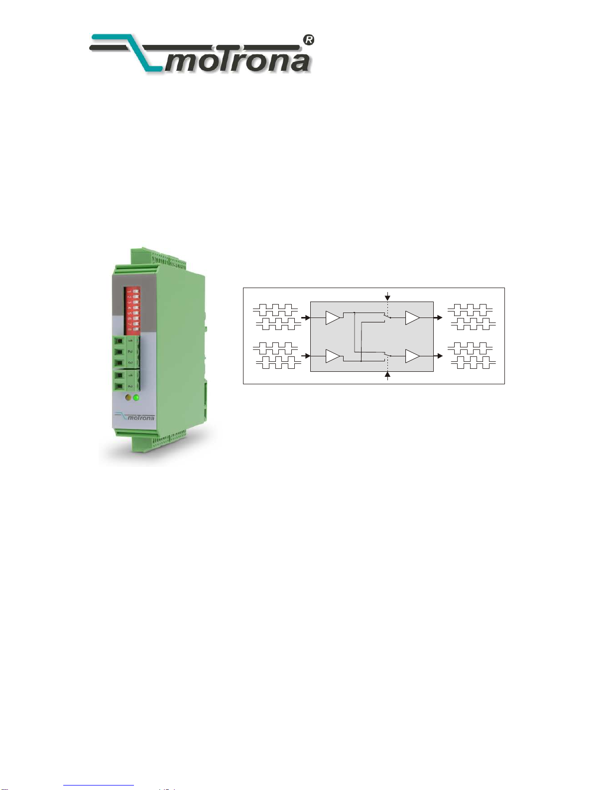
GV 210
Cross Switcher and Splitter
for Incremental Encoder Signals
In1
Control 1
Control 2
In2
Out1
Out2
A, /A, B, /B, Z, /Z
A, /A, B, /B, Z, /Z
A, /A, B, /B, Z, /Z
A, /A, B, /B, Z, /Z
Universal encoder interface, applicable as level converter, encoder splitter and
encoder cross switch
Two encoder inputs A, B, Z and /A, /B, /Z, adjustable to either TTL/RS422 level
or to HTL (10-30 volts) level
Two signal outputs A, B, Z and /A, /B, /Z, likewise adjustable to either TTL/RS422
or HTL (10-30 volts) level
High frequency range ( 1 MHz )
Contactless and bounce-free switch-over between the encoder channels, by remote
control signals
Power supply 12-30 volts DC, auxiliary output 5 volts for encoder supply
Operating Instructions

GV21002d_e.doc / Sep-13 Page 2 / 11
Safety Instructions
This manual is an essential part of the unit and contains important hints about
function, correct handling and commissioning. Non-observance can result in
damage to the unit or the machine, or even in injury to persons using the
equipment !
The unit must only be installed, connected and activated by a qualified electrician
It is a must to observe all general and also all country-specific and application-
specific safety standards
When this unit is used with applications where failure or maloperation could cause
damage to a machine or hazard to the operating staff, it is indispensable to meet
effective precautions in order to avoid such consequences
Regarding installation, wiring, environmental conditions, screening of cables and
earthing, you must follow the general standards of industrial automation industry
- Errors and omissions excepted –
Version:
Description:
GV21001b/ Feb.05 /af/hk
Original version
r
eleased
GV21001c/ Jul. 05 /hk
Terminal assignments and coding (X1
–
X5)
GV21001d/ Aug.05 /hk
Clarification RS422 /differential and HTL /single
-
ended operation
GV210
01e/ Jul.07 /hk
Corrections TTL
-
single
-
ended, outlines and dimensions
GV21002a/ Feb 08 /hk
New version, 1 MHz, DIL switch for TTL single
-
ended
GV21002
b
/
Dec
11
/
mb
Temperature range
GV21002c/ Apr 12 /pp
Chapt. 5 : Corrected Dimension Drawing (DIL)
GV21
002d/
Sep
13 /af/nw
Correction “Technical Specification”

GV21002d_e.doc / Sep-13 Page 3 / 11
Table of Contents
1. Applications ................................................................................................ 4
1.1. Dual level converter .................................................................................................4
1.2. Encoder splitter (dual output)...................................................................................4
1.3. Encoder signal switcher ...........................................................................................5
2. Connection Diagram .................................................................................... 6
2.1. Power supply............................................................................................................6
2.2. Control inputs...........................................................................................................6
2.3. Encoder inputs..........................................................................................................6
2.4. Asymmetric TTL Inputs.............................................................................................7
2.5. Outputs.....................................................................................................................7
3. The Front LEDs............................................................................................. 8
4. Switch Settings ........................................................................................... 9
5. Dimensions................................................................................................ 10
6. Technical Specifications............................................................................ 11
GV21002d_e.doc / Sep-13 Page 4 / 11
1. Applications
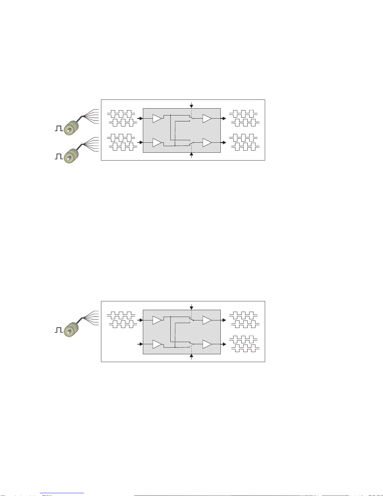
1.1. Dual level converter
In1
Control 1
= LOW
Control 2
= HIGH
In2
Out1
Out2
RS422 or
HTL 10-30V
HTL 10-30V
or RS422
RS422 or
HTL 10-30V
HTL 10-30V
or RS422
A, /A, B, /B, Z, /Z
A, /A, B, /B, Z, /Z
A, /A, B, /B, Z, /Z
A, /A, B, /B, Z, /Z
Both inputs can be individually set to either symmetric (differential) format using
A, /A, B, /B, Z, /Z channels, or to asymmetric (single-ended) format using A, B, Z channels only.
Acceptable input levels are RS422, TTL and HTL 10-30 volts.
The output format can again be selected individually for each output.
The outputs provide always all signals including the inverted channels, even when no inverted
signals are applied to the input.
With Control input 1 = LOW (or unconnected) and Control input 2 = HIGH the signal ways are as
shown in the drawing above, featuring two independent level converters.
1.2. Encoder splitter (dual output)
In1
Control 1
= LOW (n.c.)
Control 2
= LOW (n.c.)
In2
Out1
Out2
RS422 or
HTL 10-30V
HTL 10-30V
or RS422
HTL 10-30V
or RS422
N.C.
A, /A, B, /B, Z, /Z
A, /A, B, /B, Z, /Z
A, /A, B, /B, Z, /Z
Input 1 is used as encoder input, and Input 2 remains unconnected. The input can be set to
either symmetric (differential) format using A, /A, B, /B, Z, /Z channels, or to asymmetric
(single-ended) format using A, B, Z channels only.
Acceptable input levels are RS422, TTL and HTL 10-30 volts.
The output standard can again be selected individually for each output. The outputs provide
always all signals including the inverted channels, even when no inverted signals are applied to
the input. Control1 and Control2 remain unconnected with this application.
GV21002d_e.doc / Sep-13 Page 5 / 11
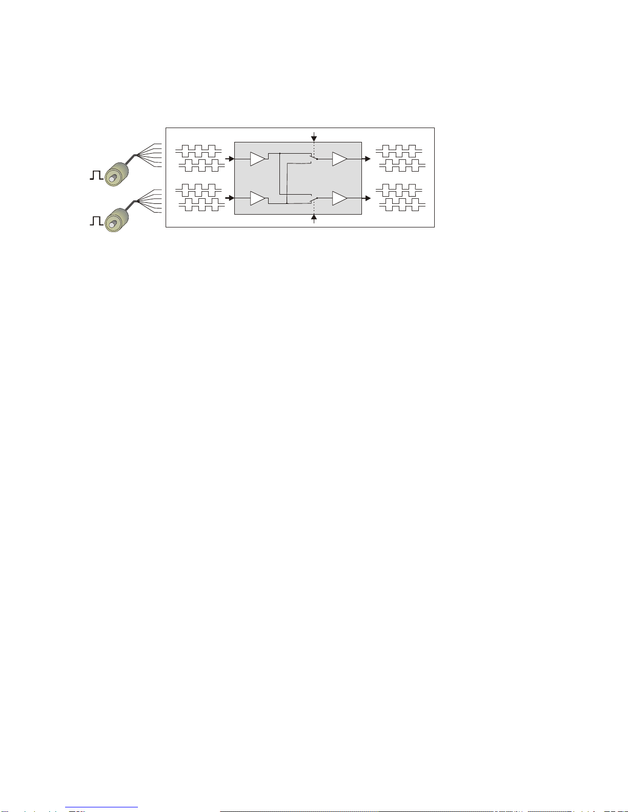
1.3. Encoder signal switcher
In1
Control 1
LO = In1, Hi = In2
Control 2
LO = In1, HI = In2
In2
Out1
Out2
RS422 or
HTL 10-30V
HTL 10-30V
or RS422
RS422 or
HTL 10-30V
HTL 10-30V
or RS422
A, /A, B, /B, Z, /Z
A, /A, B, /B, Z, /Z
A, /A, B, /B, Z, /Z
A, /A, B, /B, Z, /Z
Both inputs can be individually set to either symmetric (differential) format using
A, /A, B, /B, Z, /Z channels, or to asymmetric (single-ended) format using A, B, Z channels only.
Acceptable input levels are RS422, TTL and HTL 10-30 volts.
The output standard can again be selected individually for each output.
The outputs provide always all signals including the inverted channels, even when no inverted
signals are applied to the input.
Inputs Control1 and Control2 select the signal ways:
LOW: The corresponding output is connected to input 1
HIGH: The corresponding output is connected to input 2
GV21002d_e.doc / Sep-13 Page 6 / 11
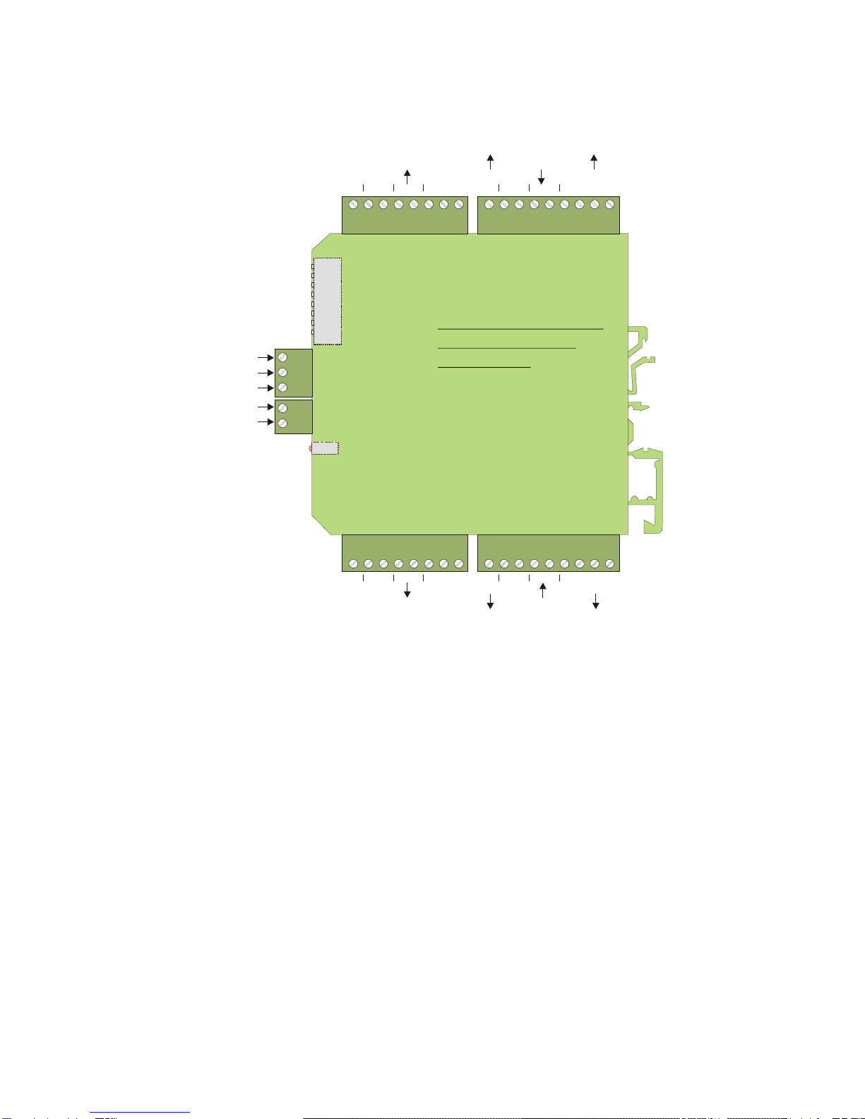
2. Connection Diagram
Z
Z
B
B
A
A
5.2V
GND
Input 2
1
2
3
45678
LED
DIL Switch
12 3 4 5
6
7
8
9
12 3 4 5 6 7 8
Z
Z
B
B
A
A
GND
24V
Output 2
Z
Z
B
B
A
A
5
.
2
V
G
N
D
Terminal strip 9-pos.
Input 1
Terminal strip 8-pos.
Z
Z
B
B
A
A
G
N
D
2
4
V
Output 1
9
8
7
6
5
4
3
2
1
8
7
6
5
4
3
2
1
3 2 12 1
Control 1
GND
24V
GND
Power supply
Control 2
X1
X2 X3
X4X5
X6
Connectors are mechanically
coded and therefore not
interchangeable
Terminal strip 9-pos.
Terminal strip 8-pos.
2.1. Power supply
The unit requires a 12–30 volts DC power supply via the 2-position power terminal on the front
side (terminal 1 = +, terminal 2 = GND)
The current consumption is about 50 mA (aux. voltages and outputs unloaded)
2.2. Control inputs
The control inputs are accessible via the 3-position terminal strip on the front. They are in LOW
state when unconnected. To switch the inputs to HIGH state, a signal from +10 to +30 volts
must be applied to the corresponding terminal.
2.3. Encoder inputs
The input lines can be configured for different requirements by DIL switch setting. The
following input formats can be used:
Single-ended signals (asymmetric), channels A, B and Z only without inverted inputs
(Level is HTL 10–30 volts in general, exceptionally also TTL, see 2.4)
Differential signals (symmetric), channels A, /A, B, /B, Z, /Z
(levels either according to RS422 standard or TTL or HTL 10-30 volts)
GV21002d_e.doc / Sep-13 Page 7 / 11
A, B and Z may at any time also be independent single signals, e.g. from proximities, photocells
etc. Since the level of every channel is selected individually (see DIL-switch), it is possible to
use different levels on the inputs. Consequently it is e.g. possible to take the position
information from the A, /A, B and /B channels of a RS422 encoder, but to add the
corresponding Z index pulse as a HTL signal from a remote photocell
With HTL signals, the switching threshold lies between 6.5 and 8 volts. The input uses an
internal pull-down resistor of 5kOhms.
Every of the two input terminals provides two auxiliary voltage outputs for easy encoder supply:
+5.2 volts/125 mA and +24 volts*/125 mA
*) Output = power supply voltage – 2 volts
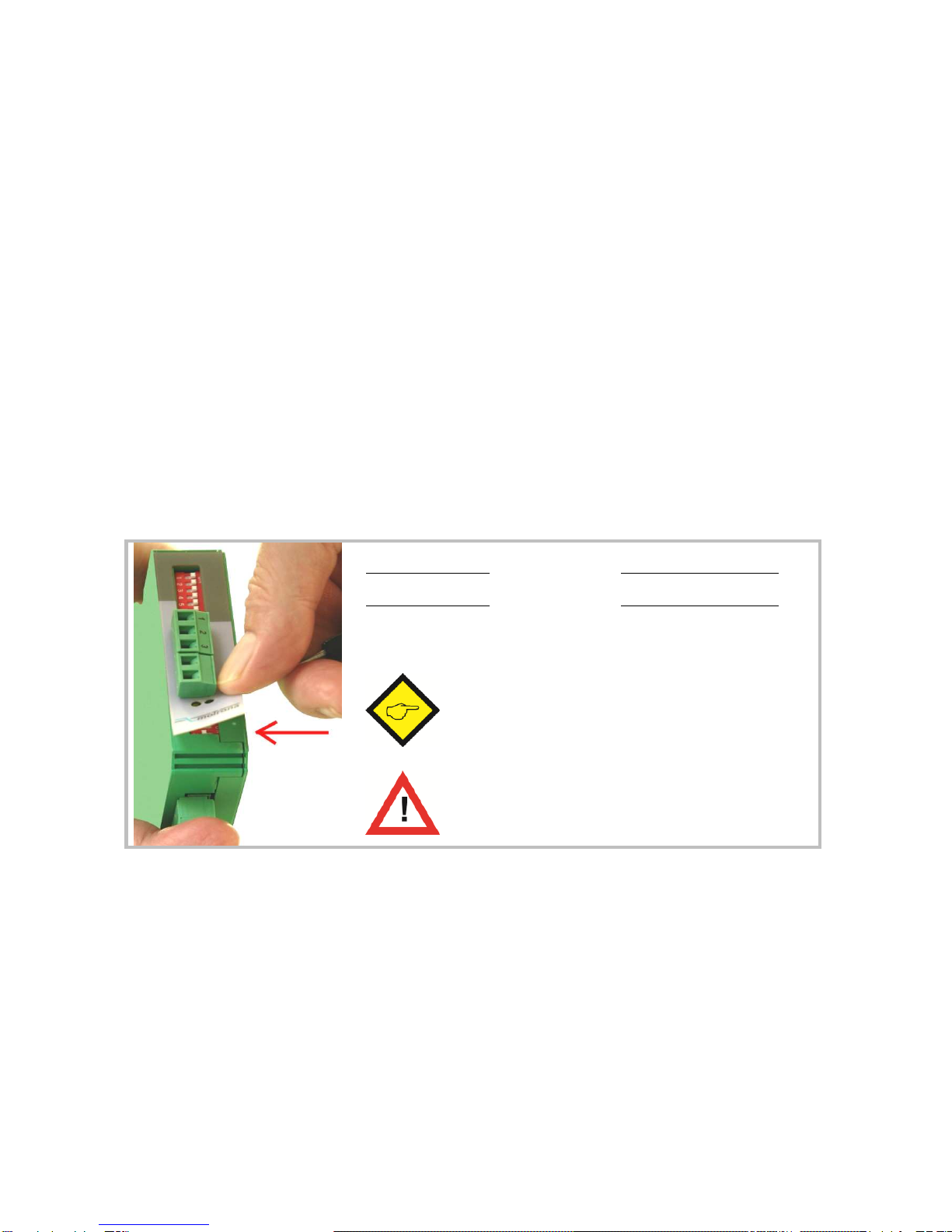
2.4. Asymmetric TTL Inputs
Only when exceptionally asymmetric TTL input signals must be processed (i.e. TTL signals
without inverted signal), a 2-position DIL switch located behind the front plate must be set. This
hidden switch becomes accessible by slightly lifting up the front foil at the lower end
(e.g. by means of a small screw driver)
Switch position 1 is responsible for all channels of Input 1
Switch position 2 is responsible for all channels of Input 2
OFF
= Asymmetric operation with HTL level (10
–
30 V)
ON
= Asymmetri
c operation with
TTL
-
Pegel
Ex factory both switches are OFF, i.e. any
single-ended operation requires HTL levels
(this is the normal case)
Asymmetric TTL levels are most sensitive to
noise and interference, therefore not suitable for
cable transmission in an industrial environment!
For all general applications please do not touch the DIL switch hidden behind the front plate !
2.5. Outputs
The outputs provide push-pull characteristics. When set to TTL/RS422 level, the corresponding
output swing is always 5 volts. When set to HTL, the output swing depends on the power
supply input (12 – 30volts).
All outputs are short-circuit-proof.
At any time the signal and the appropriate inverted signal are both available at the output, even
when no inverted signal is applied to the input.

GV21002d_e.doc / Sep-13 Page 8 / 11
3. The Front LEDs
The green LED is lit as soon as a power supply voltage is applied to the unit.
The yellow LED indicates the state of the Control inputs and the basic function of the unit:
Yellow LED off: Control1 and Control2 are either both LOW or both HIGH at the same time. In
this case the unit operates as a splitter (both outputs are connected to the same input)
Yellow LED on: Control1 and Control2 have different states. In this case the unit operates as a
dual level converter or as a switcher (the outputs are connected to different inputs)
GV21002d_e.doc / Sep-13 Page 9 / 11
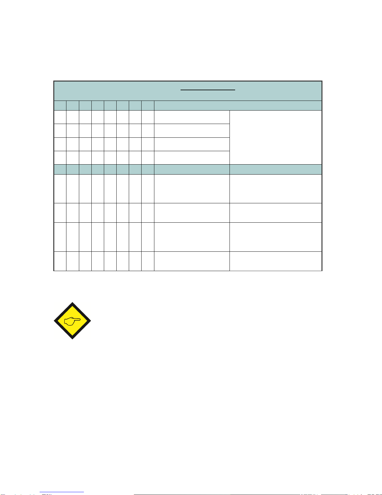
4. Switch Settings
The DIL switch sets level and standard of inputs and outputs:
0=OFF
DIL switch settings
1=ON
8
7
6
5
4
3
2
1
0Output 1: TTL / RS422 The output levels are 5 volts
with TTL setting and
correspond to the power
supply voltage with HTL
setting
1Output 1: HTL
0Output 2: TTL / RS422
1Output 2: HTL
0
(Z)
0
(B)
0
(A) Input 1: differential
(A, /A, B, /B, Z, /Z)
Both, input and inverted input
must be used. Levels from 2 to
30 volts are acceptable.
1
(Z)
1
(B)
1
(A)
Input 1:
single
-
ended
(A,B,Z) with HTL level *)
Inverted inputs remain
open,
level must be HTL 10-30 volts
0
(Z)
0
(B)
0
(A) Input 2: differential
(A, /A, B, /B, Z, /Z)
Both, input and inverte
d input
must be used. Levels from 2 to
30 volts are acceptable.
1
(Z)
1
(B)
1
(A)
Input
2
:
single
-
ended
(A,B,Z) with HTL level *)
Inverted inputs remain
open,
level must be HTL 10-30 volts
*) This setting can also be used with asymmetric (single-ended) TTL levels. See 2.4
Please set unused input lines to “single-ended” HTL at any time!
It is not mandatory to use the same level for all channels of an input. The indications (A), (B), (Z)
show which switch position is responsible for which channel.
When e.g. positions 3 and 4 are set to “0” and position 5 is set to “1”, Input1 would accept
A, /A, B, /B at RS422 standard, and the Z index as a HTL single-ended signal.
Consequently it is possible to e.g. generate an Index from a remote photocell, whereas the
impulses come from the RS422 encoder simulation of a drive system.
GV21002d_e.doc / Sep-13 Page 10 / 11
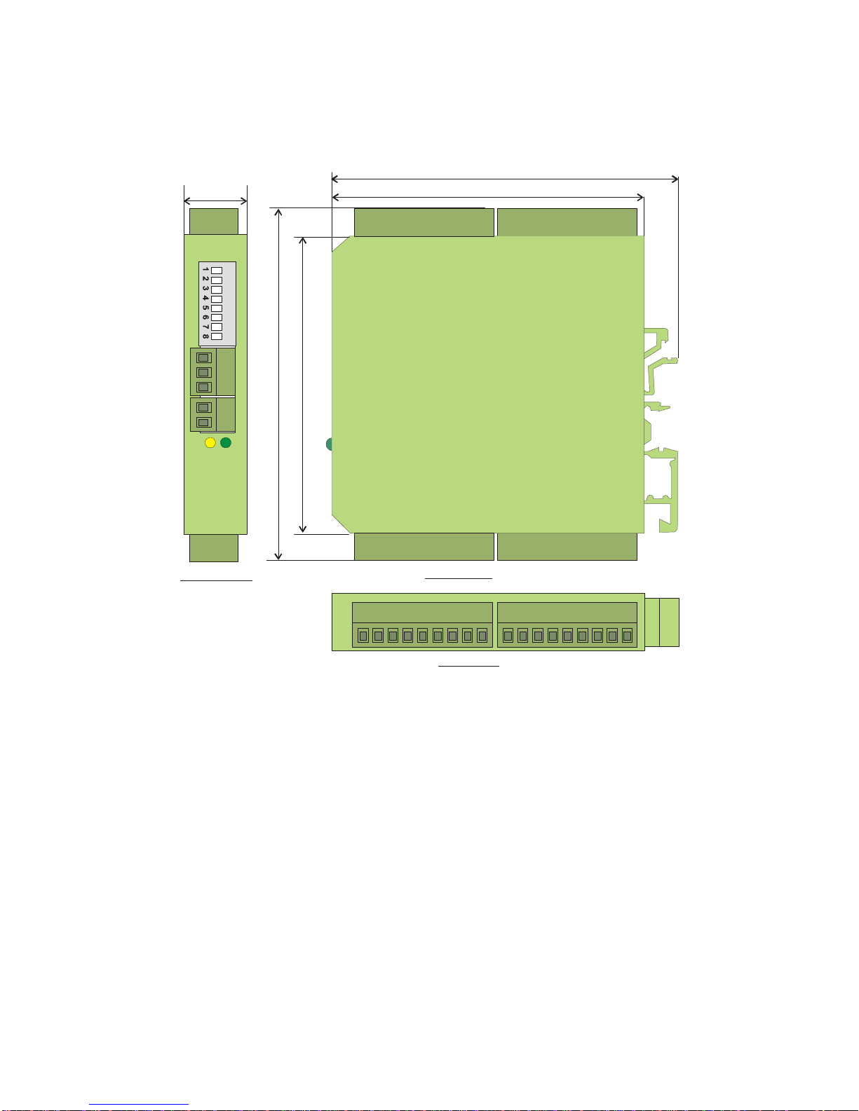
5. Dimensions
102 (4.016”)
91 (3.583”)
8
2
.
5
(
3
.
2
4
8
”
)
1
0
2
(
4
.
0
1
6
”
)
22.5
(0.886”)
ON
Side view
Top view
Front view

GV21002d_e.doc / Sep-13 Page 11 / 11
6. Technical Specifications
Power supply Vin
:
12
-
30 Vdc
Power consumption
:
50 mA (no
-
load operation)
Aux. encoder supply
output
:
5.2 volts
and
Vin
–
2 volts, 2x 125 mA
(short-circuit-proof)
Max. frequency
:
1 MHz
(RS422
or TTL differential
)
250 kHz (HTL and TTL single-ended)
Inputs
:
Single
-
ended A, B, Z (2x) or
differential A, /A, B, /B, Z, /Z (2x), 2 – 30 volts
Outputs
:
Push
-
pull A, /A, B, /B, Z, /Z (2x)
Level 5 volts (50 mA) – 30 volts (30 mA)
short-circuit-proof
Signal propagation delay
:
approx. 600 nsec.
Temperature range *)
:
Operation:
-
20°
-
+60°C (
-
04°
-
+140°F)
Storage: -30° - +75°C (-22° - +167°F)
Weight
:
ca. 100 g
Conformity and standards
:
EMC 2004/108/EC
:
EN 61000
-
6
-
2
EN 61000-6-3
*) Humidity non-condensing
Other manuals for GV210
1
Table of contents
Other Motrona Switch manuals


