Movincool OFFICE PRO 18 User manual

SERVICE MANUAL
OFFICE PRO 18
SERIAL NUMBER FROM APRIL 2007 (0407) TO PRESENT
DocID: 00G00014EB

© 2011 DENSO SALES CALIFORNIA, INC.
All rights reserved. This book may not be reproduced or copied, in
whole or in part, without the written permission of the publisher. DENSO
SALES CALIFORNIA, INC. reserves the right to make changes without
prior notice. MovinCool®, Office Pro® and SpotCool® are registered
trademarks of DENSO Corporation.

Table of Contents
Table of Contents
Operation Section
1. PRECAUTIONS FOR SAFETY
1.1 Foreword. . . . . . . . . . . . . . . . . . . . . . . . . . . . . . . . . . . . . . . . . . . . . . . . . . . . . . . . . . . . . . . . . . . . . . . 6
1.2 Definition of Terms . . . . . . . . . . . . . . . . . . . . . . . . . . . . . . . . . . . . . . . . . . . . . . . . . . . . . . . . . . . . . . . 6
1.3 General Precautions . . . . . . . . . . . . . . . . . . . . . . . . . . . . . . . . . . . . . . . . . . . . . . . . . . . . . . . . . . . . . . 6
2. CONSTRUCTION
2.1 Exterior Dimensions . . . . . . . . . . . . . . . . . . . . . . . . . . . . . . . . . . . . . . . . . . . . . . . . . . . . . . . . . . . . . . 7
2.2 Exterior Components . . . . . . . . . . . . . . . . . . . . . . . . . . . . . . . . . . . . . . . . . . . . . . . . . . . . . . . . . . . . . 8
2.3 Internal Structure . . . . . . . . . . . . . . . . . . . . . . . . . . . . . . . . . . . . . . . . . . . . . . . . . . . . . . . . . . . . . . . . 9
2.4 Basic Construction . . . . . . . . . . . . . . . . . . . . . . . . . . . . . . . . . . . . . . . . . . . . . . . . . . . . . . . . . . . . . . . 9
2.5 Air Flow. . . . . . . . . . . . . . . . . . . . . . . . . . . . . . . . . . . . . . . . . . . . . . . . . . . . . . . . . . . . . . . . . . . . . . . 10
2.6 Compressor and Fans . . . . . . . . . . . . . . . . . . . . . . . . . . . . . . . . . . . . . . . . . . . . . . . . . . . . . . . . . . . 10
2.7 Drain Tank. . . . . . . . . . . . . . . . . . . . . . . . . . . . . . . . . . . . . . . . . . . . . . . . . . . . . . . . . . . . . . . . . . . . . 10
3. SPECIFICATIONS
3.1 Technical Specifications . . . . . . . . . . . . . . . . . . . . . . . . . . . . . . . . . . . . . . . . . . . . . . . . . . . . . . . . . . 11
3.2 Characteristics . . . . . . . . . . . . . . . . . . . . . . . . . . . . . . . . . . . . . . . . . . . . . . . . . . . . . . . . . . . . . . . . . 13
4. REFRIGERATION SYSTEM
4.1 Refrigeration System Construction . . . . . . . . . . . . . . . . . . . . . . . . . . . . . . . . . . . . . . . . . . . . . . . . . . 14
4.2 Compressor . . . . . . . . . . . . . . . . . . . . . . . . . . . . . . . . . . . . . . . . . . . . . . . . . . . . . . . . . . . . . . . . . . . 15
4.3 Condenser . . . . . . . . . . . . . . . . . . . . . . . . . . . . . . . . . . . . . . . . . . . . . . . . . . . . . . . . . . . . . . . . . . . . 18
4.4 Capillary Tube. . . . . . . . . . . . . . . . . . . . . . . . . . . . . . . . . . . . . . . . . . . . . . . . . . . . . . . . . . . . . . . . . . 18
4.5 Evaporator . . . . . . . . . . . . . . . . . . . . . . . . . . . . . . . . . . . . . . . . . . . . . . . . . . . . . . . . . . . . . . . . . . . . 19
4.6 Accumulator . . . . . . . . . . . . . . . . . . . . . . . . . . . . . . . . . . . . . . . . . . . . . . . . . . . . . . . . . . . . . . . . . . . 19
5. ELECTRICAL SYSTEM
5.1 Circuit Diagram and Control Box . . . . . . . . . . . . . . . . . . . . . . . . . . . . . . . . . . . . . . . . . . . . . . . . . . . 20
5.2 Basic Operation of Electrical Circuit . . . . . . . . . . . . . . . . . . . . . . . . . . . . . . . . . . . . . . . . . . . . . . . . . 21
5.3 Control Box . . . . . . . . . . . . . . . . . . . . . . . . . . . . . . . . . . . . . . . . . . . . . . . . . . . . . . . . . . . . . . . . . . . . 22
5.4 Fan Motor . . . . . . . . . . . . . . . . . . . . . . . . . . . . . . . . . . . . . . . . . . . . . . . . . . . . . . . . . . . . . . . . . . . . . 24
5.5 Compressor Motor . . . . . . . . . . . . . . . . . . . . . . . . . . . . . . . . . . . . . . . . . . . . . . . . . . . . . . . . . . . . . . 24
5.6 Compressor Overload Relay . . . . . . . . . . . . . . . . . . . . . . . . . . . . . . . . . . . . . . . . . . . . . . . . . . . . . . 25
5.7 Power Cord with LCDI . . . . . . . . . . . . . . . . . . . . . . . . . . . . . . . . . . . . . . . . . . . . . . . . . . . . . . . . . . . 25
5.8 Drain Switch . . . . . . . . . . . . . . . . . . . . . . . . . . . . . . . . . . . . . . . . . . . . . . . . . . . . . . . . . . . . . . . . . . . 26
5.9 Condensate Pump Kit (optional). . . . . . . . . . . . . . . . . . . . . . . . . . . . . . . . . . . . . . . . . . . . . . . . . . . . 27

Table of Contents
5.10 Automatic Restart after Power Interruption. . . . . . . . . . . . . . . . . . . . . . . . . . . . . . . . . . . . . . . . . . . . 27
5.11 Compressor Protection . . . . . . . . . . . . . . . . . . . . . . . . . . . . . . . . . . . . . . . . . . . . . . . . . . . . . . . . . . . 27
5.12 Temperature Control . . . . . . . . . . . . . . . . . . . . . . . . . . . . . . . . . . . . . . . . . . . . . . . . . . . . . . . . . . . . . 27
5.13 Fan Mode Control Switch . . . . . . . . . . . . . . . . . . . . . . . . . . . . . . . . . . . . . . . . . . . . . . . . . . . . . . . . . 28
5.14 Temperature Scale Display Switch . . . . . . . . . . . . . . . . . . . . . . . . . . . . . . . . . . . . . . . . . . . . . . . . . . 28
5.15 Warning Signal Connection (Output Signal Terminal L+ and L-) . . . . . . . . . . . . . . . . . . . . . . . . . . . 29
5.16 Fire Alarm Control Panel Connection (Input Signal Terminal E+ and E-) . . . . . . . . . . . . . . . . . . . . . 30

Table of Contents
Repair Section
6. TROUBLESHOOTING
6.1 Troubleshooting . . . . . . . . . . . . . . . . . . . . . . . . . . . . . . . . . . . . . . . . . . . . . . . . . . . . . . . . . . . . . . . . 31
6.2 Self-Diagnostic Codes . . . . . . . . . . . . . . . . . . . . . . . . . . . . . . . . . . . . . . . . . . . . . . . . . . . . . . . . . . . 32
6.3 Troubleshooting Chart . . . . . . . . . . . . . . . . . . . . . . . . . . . . . . . . . . . . . . . . . . . . . . . . . . . . . . . . . . . 34
6.4 Basic Inspection . . . . . . . . . . . . . . . . . . . . . . . . . . . . . . . . . . . . . . . . . . . . . . . . . . . . . . . . . . . . . . . . 39
7. DISASSEMBLY
7.1 Parts Construction . . . . . . . . . . . . . . . . . . . . . . . . . . . . . . . . . . . . . . . . . . . . . . . . . . . . . . . . . . . . . . 41
7.2 Disassembly . . . . . . . . . . . . . . . . . . . . . . . . . . . . . . . . . . . . . . . . . . . . . . . . . . . . . . . . . . . . . . . . . . . 42
7.3 Removal of Electrical Parts. . . . . . . . . . . . . . . . . . . . . . . . . . . . . . . . . . . . . . . . . . . . . . . . . . . . . . . . 44
7.4 Removal of Blower Assembly . . . . . . . . . . . . . . . . . . . . . . . . . . . . . . . . . . . . . . . . . . . . . . . . . . . . . . 48
7.5 Inspection of Capacitor (for Fan Motor and Compressor) . . . . . . . . . . . . . . . . . . . . . . . . . . . . . . . . 50
7.6 Inspection of Drain Switch . . . . . . . . . . . . . . . . . . . . . . . . . . . . . . . . . . . . . . . . . . . . . . . . . . . . . . . . 50
7.7 Inspection of Fan Motor . . . . . . . . . . . . . . . . . . . . . . . . . . . . . . . . . . . . . . . . . . . . . . . . . . . . . . . . . . 51
7.8 Inspection of Compressor Motor. . . . . . . . . . . . . . . . . . . . . . . . . . . . . . . . . . . . . . . . . . . . . . . . . . . . 51
7.9 Inspection of Wiring Connection . . . . . . . . . . . . . . . . . . . . . . . . . . . . . . . . . . . . . . . . . . . . . . . . . . . . 51
7.10 Inspection of Thermistor . . . . . . . . . . . . . . . . . . . . . . . . . . . . . . . . . . . . . . . . . . . . . . . . . . . . . . . . . . 51
7.11 Inspection . . . . . . . . . . . . . . . . . . . . . . . . . . . . . . . . . . . . . . . . . . . . . . . . . . . . . . . . . . . . . . . . . . . . . 52
8. REFRIGERATION SYSTEM REPAIR
8.1 Repair of Refrigeration System. . . . . . . . . . . . . . . . . . . . . . . . . . . . . . . . . . . . . . . . . . . . . . . . . . . . . 53
8.2 Removal of Refrigeration Cycle Components. . . . . . . . . . . . . . . . . . . . . . . . . . . . . . . . . . . . . . . . . . 55
8.3 Charging the System with R-410A Refrigerant. . . . . . . . . . . . . . . . . . . . . . . . . . . . . . . . . . . . . . . . . 56
8.4 Refrigerant Charging Work . . . . . . . . . . . . . . . . . . . . . . . . . . . . . . . . . . . . . . . . . . . . . . . . . . . . . . . . 61
9. REASSEMBLY
9.1 Removal of Unit . . . . . . . . . . . . . . . . . . . . . . . . . . . . . . . . . . . . . . . . . . . . . . . . . . . . . . . . . . . . . . . . 63
9.2 Compressor Mounting . . . . . . . . . . . . . . . . . . . . . . . . . . . . . . . . . . . . . . . . . . . . . . . . . . . . . . . . . . . 63
9.3 Blower Assembly . . . . . . . . . . . . . . . . . . . . . . . . . . . . . . . . . . . . . . . . . . . . . . . . . . . . . . . . . . . . . . . 63
9.4 Wiring Notice . . . . . . . . . . . . . . . . . . . . . . . . . . . . . . . . . . . . . . . . . . . . . . . . . . . . . . . . . . . . . . . . . . 63
9.5 Perform the Inspection . . . . . . . . . . . . . . . . . . . . . . . . . . . . . . . . . . . . . . . . . . . . . . . . . . . . . . . . . . . 64
9.6 Caster Maintenance . . . . . . . . . . . . . . . . . . . . . . . . . . . . . . . . . . . . . . . . . . . . . . . . . . . . . . . . . . . . . 64
9.7 Schematic . . . . . . . . . . . . . . . . . . . . . . . . . . . . . . . . . . . . . . . . . . . . . . . . . . . . . . . . . . . . . . . . . . . . . 65

Operation Section
6
1. PRECAUTIONS FOR SAFETY
1.1 Foreword
• This manual has been published to service the MovinCool Office Pro 18. Please use this service
manual only when servicing the Office Pro 18.
1.2 Definition of Terms
1.3 General Precautions
WARNING
• All electrical work should only be performed by qualified electrical personnel. Repair to
electrical components by non-certified technicians may result in personal injury and/or
damage to the unit. All electrical components replaced must be genuine MovinCool parts,
purchased from an authorized reseller.
• Before replacing any refrigeration components, recover the refrigerant using standard
recovery procedures and equipment.
• When handling refrigerant, always wear proper eye protection and do not allow the
refrigerant to come in contact with your skin.
• Do not expose refrigerant to an open flame.
• The power supply for this unit should be a dedicated single outlet circuit with UL
recognized short-circuit and ground-fault protective breaker to prevent electrical shock
from the unit.
• When brazing any tubing, always wear eye protection, and work only in a well ventilated
area.
• Disconnect power before servicing unit.
• Be careful of any sharp edges when working on unit.
Describes precautions that should be observed in order to prevent injury to
the user during installation or unit operation.
Describes precautions that should be observed in order to prevent damage to
the unit or its components, which may occur during installation or unit
operation if sufficient care is not taken.
NOTE Provides additional information that facilitates installation or unit operation.
WARNING
CAUTION
Operation Section 7
2. CONSTRUCTION
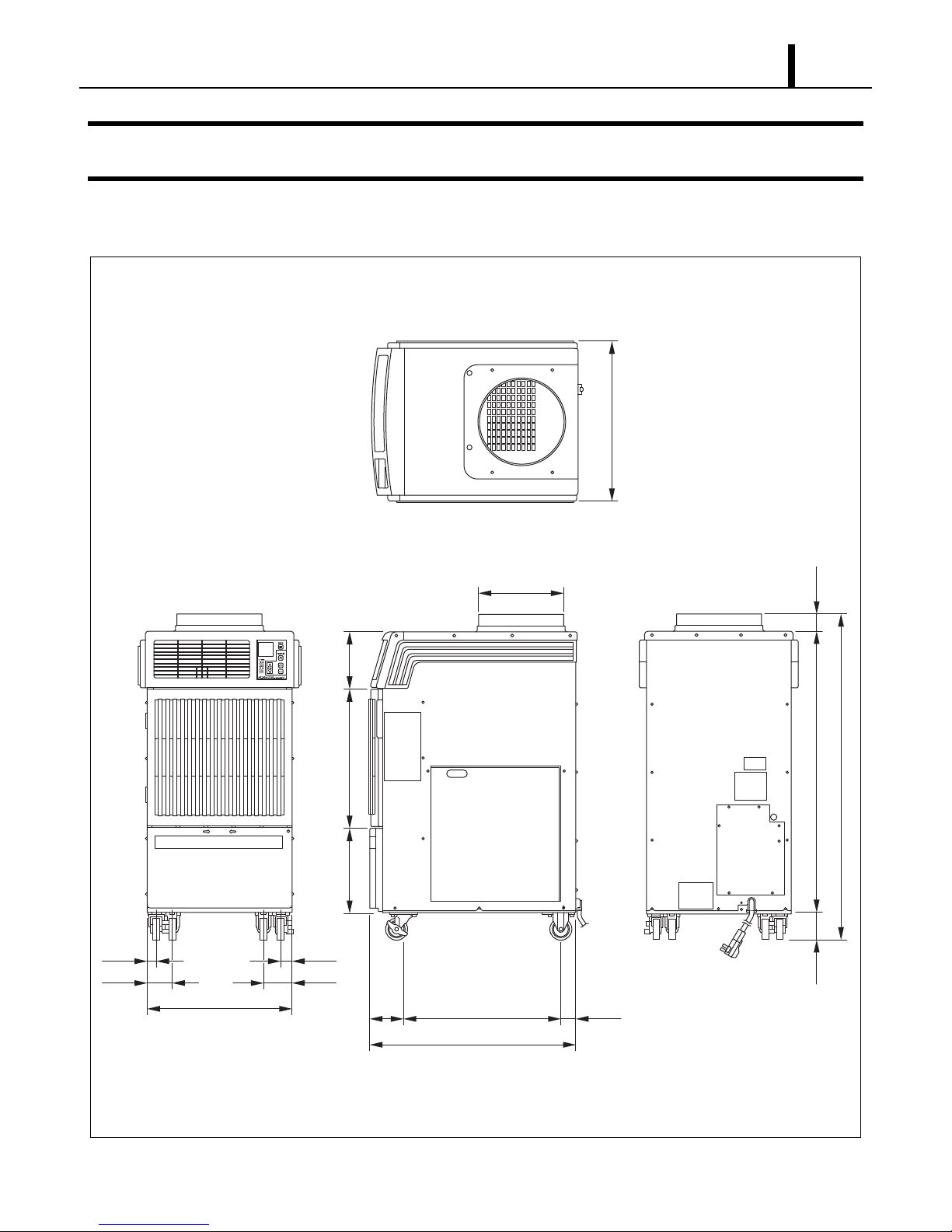
2.1 Exterior Dimensions
I002232
(21.4)
(2.4)(37.8)(3.7)
(43.8)
(1.4)
(3.5)
(1.4)
(3.5)
(Unit: inch)
(19.3)
(7.5)(11.6) (18.7)
(20.9)
(DIA. 11.6)
(27.4)
(4.6) (2.0)
Operation Section
8
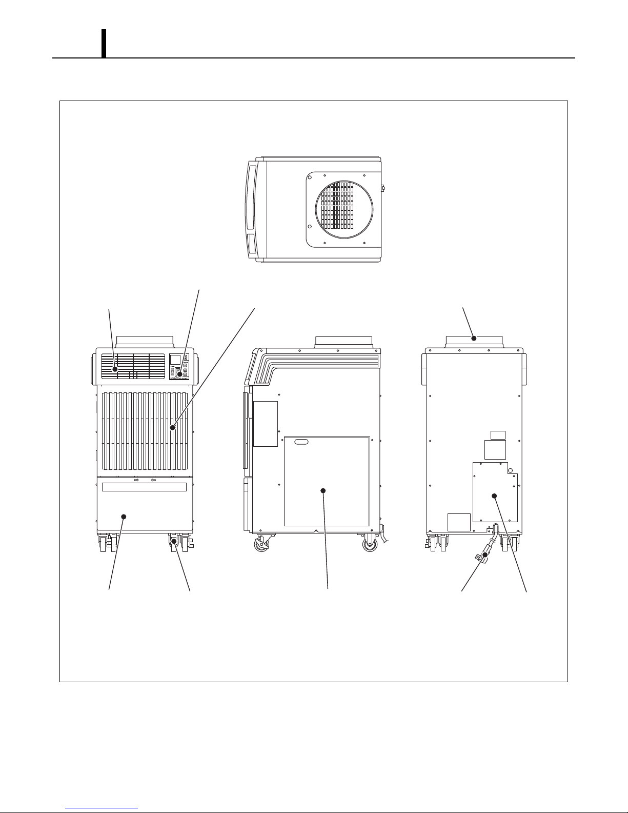
2.2 Exterior Components
I002233
Cold Air Outlet Grill Evaporator Air Inlet Grill Condenser Air Outlet Duct
Service PanelPower Cord
Condenser Air Inlet Panel
CasterDrain Tank Cover
Operation Panel
Operation Section 9
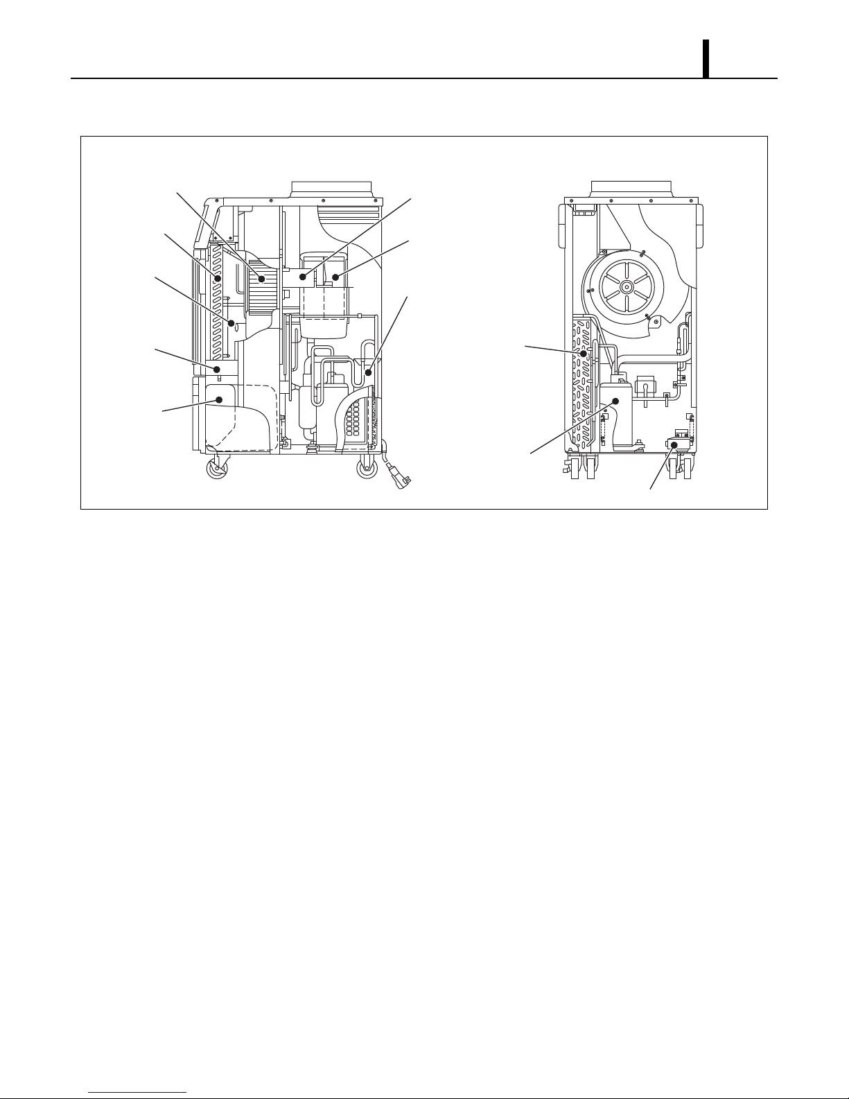
2.3 Internal Structure
2.4 Basic Construction
• The MovinCool Office Pro 18 is compact in construction because the condenser and the
evaporator are enclosed in one unit. The interior is divided into three sections. The upper front
face is equipped with the evaporator, and the lower front face contains the drain tank and
condensate pump (Optional). The rear section contains the condenser, the compressor and the
control box.
I002234
Condenser
Compressor
Drain Switch
Fan Motor
Control Box
Fan
(Condenser)
Fan
(Evaporator)
Evaporator
Capillary
Tube
Drain Pan
Drain Tank
Operation Section
10
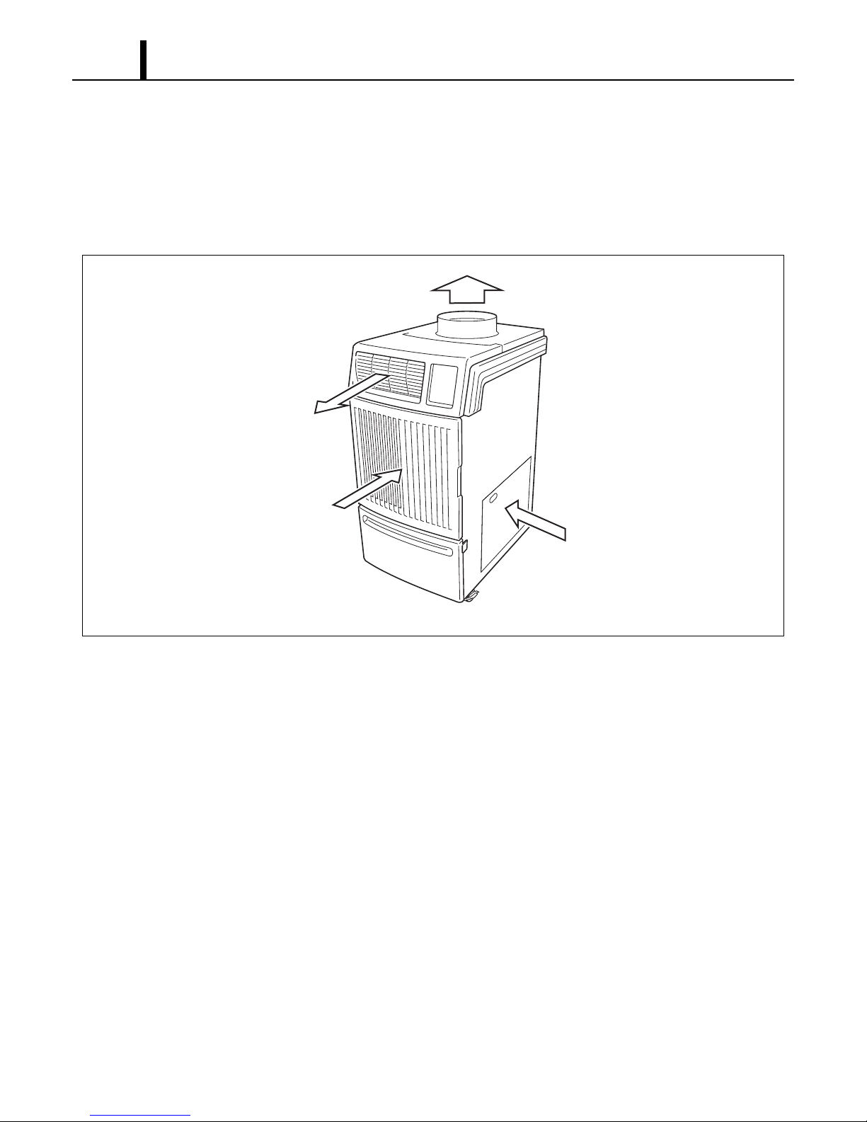
2.5 Air Flow
• Air drawn from the right side face passes through the condenser which extracts the heat. This
hot air is blown out through the upper exhaust air duct. Air taken in from the front face is cooled
by the evaporator and then blown through the cool air vent. All the air inlets are equipped with
filters, and the exhaust air duct is protected by metal grill.
2.6 Compressor and Fans
• The compressor is hermetically sealed. A two-speed fan motor with two centrifugal fans are
used to draw air across the evaporator and condenser.
2.7 Drain Tank
• A 5.0 gal (19 L) drain tank is supplied with the Office Pro 18. The condensate (water) is collected
into the tank.
The drain switch activates and stops the operation when tank reaches the level of approximately
4.0 gal (15 L).
I002235
Exhaust AirOut
Evaporator AirIn
Cool AirOut
Condenser AirIn
Operation Section 11
3. SPECIFICATIONS
3.1 Technical Specifications
ITEM SPECIFICATIONS
Electronic Features Operation Digital Programmable
Electrical Characteristics Voltage Requirement Single-Phase, 115 V, 60 Hz
Operating Voltage
Range
Max. 127 V
Min. 104 V
Starting Current 65 A
Recommended Fuse Size 20 A
FLA 15.6 A
LRA 65 A
Cooling Capacity and Power Consumption
Evaporator: 95 °F (35 °C),
60 % RH
Condenser: 95 °F (35 °C),
60 % RH
Total Cooling Capacity 16800 Btu/h (4920 W)
Sensible Cooling Capacity 8240 Btu/h (2430 W)
Power Consumption 1.7 kW
Current Consumption 15.6 A
EER 9.9
Power Factor 95 %
Compressor Type Hermetic Rotary
Output 1.16 kW
Evaporator Type of Evaporator Plate Fin
Type of Fan Centrifugal Fan
Air Flow High 540 CFM (917 m3/h)
Low 500 CFM (850 m3/h)
Max. External Static Pressure 0.31 IWG (77 Pa)
Motor Output High 0.24 kW
Low 0.17 kW
Condenser Type of Condenser Plate Fin
Type of Fan Centrifugal Fan
Air Flow High 770 CFM (1308 m3/h)
Low 710 CFM (1207 m3/h)
Max. External Static Pressure 0.23 IWG (57 Pa)
Motor Output High -
Low -

Operation Section
12
• Specifications are subject to change without notice.
< NOTE >
*1 : Serial number from April 2007 (0407) to September 2010 (0910)
*2 : Serial number from October 2010 (1010) to present
*3 : Measured at 3 feet (1.0 m) from surface of the unit.
Refrigerant Refrigerant Control Capillary Tube
Type R-410A
Amount 1.70 lb (0.77 kg)*1
1.63 lb (0.74 kg)*2
Signal Connection Fire Alarm Input (Signal Type) •No-voltage contact input
•Contact resistance less than 100 ohm
Warning Signal Output 2 A at 30 V (DC/AC) or less (resistive load)
Power Cord NEMA Plug Configuration 5-20
Gauge x Length 12 AWG (3-core) x 10 ft (3.0 m)
Dimension W x D x H 21.0 x 27.0 x 44.0 in
(538 x 685 x 1118 mm)
Weight Net 170 lb (77 kg)
Shipping 200 lb (91 kg)
Drain Tank Capacity 5.0 gal (19 L)
Operating Condition Range Inlet Air Tempera-
ture
Max. 95 °F (35 °C), 60 % RH
Min. 65 °F (18 °C), 50 % RH
Maximum Duct Length Cold Duct 25 ft (7.6 m)
Hot Duct 100 ft (30.5 m)
Sound Level*3 With Condenser
Duct
High 61 dB (A)
Low 59 dB (A)
Without Condenser
Duct
High 62 dB (A)
Low 60 dB (A)
Safety Devices Compressor Overload Protector Included
Fan Motor Overload Protector Included
Freeze Protection Thermistor Included
Full Drain Tank Switch Included
Automatic Restart (Power Interruption) Included
Compressor Time Delay 120 sec
High Pressure Interruption Included
Signal Input/Output Included
Control Devices Temperature Control Included
Programmable Timer Included
Two Speed Fan Included
ITEM SPECIFICATIONS
Operation Section 13
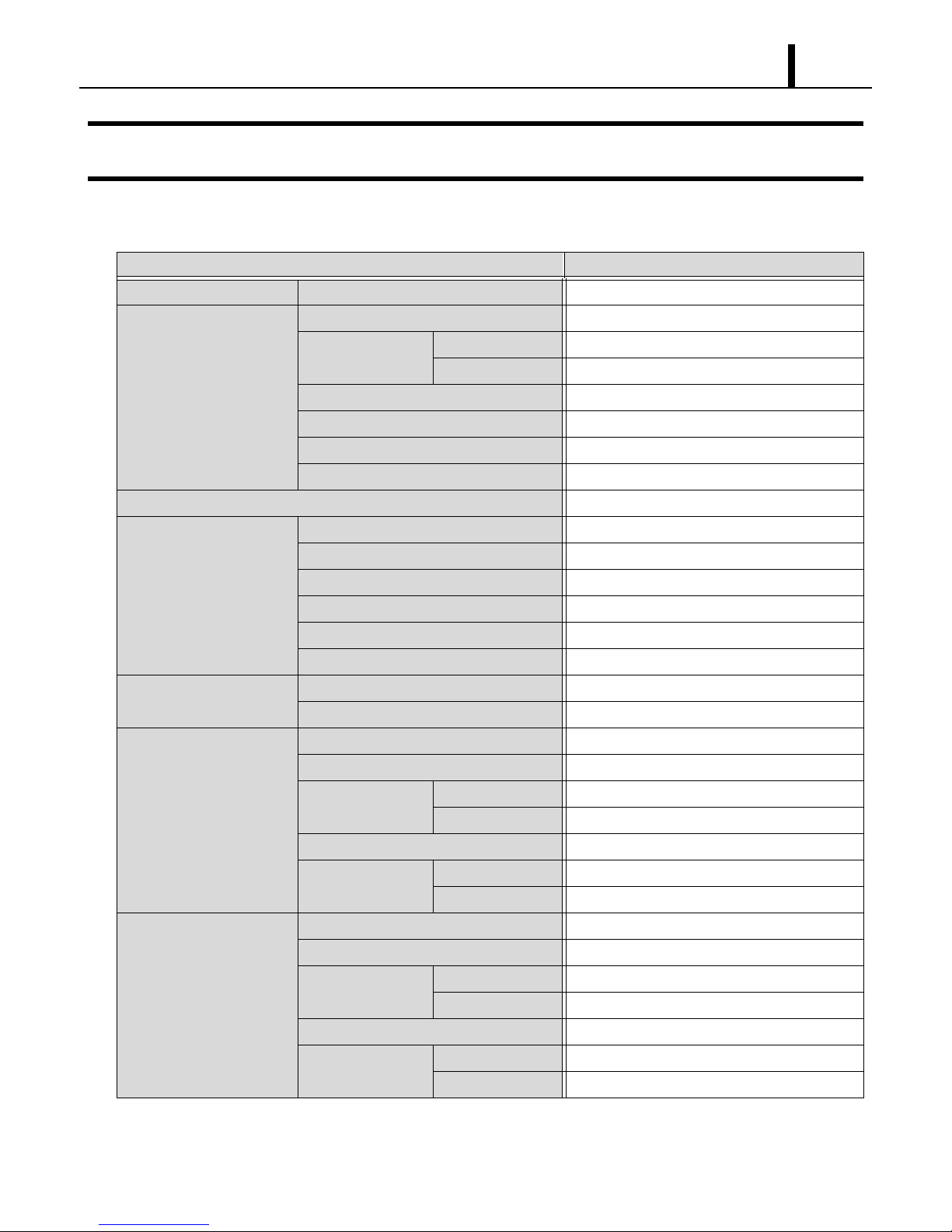
3.2 Characteristics
ILL00076-00
17
16
14
15
13
12
12
16
18
14
10
<Cooling Capacity Curve> <Cool Air Temperature Difference Curve>
25.2(14)
23.4(13)
21.6(12)
19.8(11)
18.0(10)
16.2(9)
14.4(8)
12.6(7)
10.8(6)
68(20)
77(25)
86(30)
95(35)
9.0(5)
Delta-T °F (°C)
Dry Bulb Temp. °F (°C)
Dry Bulb Temp. °F (°C)
Dry Bulb Temp. °F (°C)
Wet Bulb Temp. °F (°C)
Wet Bulb Temp. °F (°C)
(25)
77
(20)
68
(35)
95
(30)
86
(15)
59
(10)
50
Cooling Capacity (x103Btu/h)
Relative Humidity (%)
30 40 50 60 70 80
Current Consumption (A)
Power Consumption (kW)
<Power Consumption Curve> <Current Consumption Curve>
1.9
1.7
1.5
1.3
1.1
68(20)
77(25)
86(30)
95(35)
68(20)
77(25)
86(30)
95(35)
(25)
77
(20)
68
Wet Bulb Temp. °F (°C)
(35)
95
(30)
86
(25)
77
(20)
68
Operation Section
14
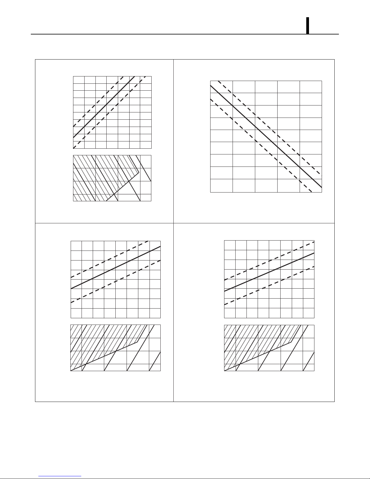
4. REFRIGERATION SYSTEM
4.1 Refrigeration System Construction
The component parts of the refrigeration system include the following:
• Compressor, Evaporator, Condenser, Capillary tube
These parts are all connected by copper tubing. All the connections have been brazed.
ILL00077-00
Condenser
Condenser
Outlet Pipe
Condenser
Inlet Pipe
Compressor
Discharge Pipe
Compressor
Compressor
Suction Pipe
Capillary Tube
Evaporator
Outlet Pipe
Evaporator Pipe
Evaporator
Flow of
Refrigerant
Compressor
Evaporator
Accumulator
Condenser
Fan
Motor
Capillary
Tubes

Operation Section 15
4.2 Compressor
• The compressor used for the unit is hermetically sealed. The compressor and the compressor
motor are in one casing.
(1) Compressor construction
•The construction of a rotary type compressor is divided into two mechanisms; the drive
mechanism (compressor motor), and the compression mechanism (compressor). When the
rotor shaft of the motor (drive mechanism) turns, the roller (compression mechanism) rotates to
compress the refrigerant.
I001675
To Condenser
Accumulator
Strainer
From Evaporator
Blade
Discharge Valve
Oil
Lubricator
Roller
Cylinder
Rotor
Stator
Terminal

Operation Section
16
(2) Basic compressor operation
•The roller (compression mechanism) is set
eccentrically with a certain distance given from
the axis of the center of the cylinder. A spring
loaded blade is mounted on the cylinder. The
roller turns to compress the refrigerant in the
space between the cylinder and eccentrically
mounted roller. The blade is in contact with the
roller by means of spring force. The blade
partitions the space between the suction side
and the discharge side to keep compressed refrigerant from returning to the suction side. There
is no suction valve. The discharge valve is designed not to open until the pressure of the
refrigerant within the cylinder reaches or exceeds discharge side pressure. As a result, the
discharge valve prevents the backward flow of refrigerant gas.
I000510
Discharge
Hole
Cylinder
Blade
Spring
Suction
Hole
Discharge
Valve
Shaft
Roller
Operation Section 17
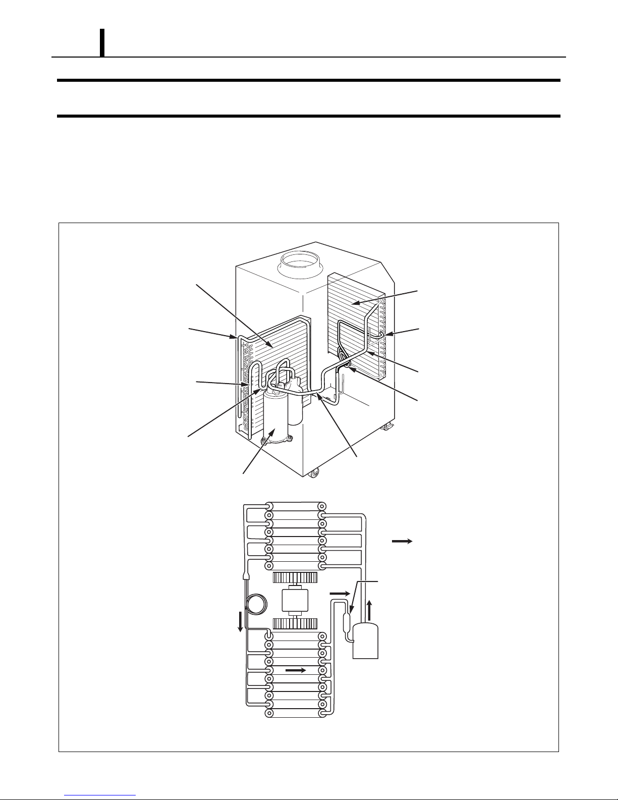
(3) Operation
1) Start of compression
1) The cylinder is filled with low pressure gas.
2) Since pressure in the discharge chamber is
higher than in the cylinder, the discharge
valve is kept closed.
2) Suction and compression
1) The pressure in the cylinder increases
gradually.
2) Refrigerant suction begins on the suction
side of the cylinder.
3) The discharge valve remains closed.
3) Discharge
1) The pressure in the cylinder exceeds that in
the discharge chamber, and the discharge
valve opens.
2) On the suction side, refrigerant suction
continues.
4) Completion of compression
1) When compression is completed, all of the
refrigerant has been drawn from the suction
chamber.
2) Operation then returns to step 1) (Start of
compression) and the above process of
suction and compression continues
repeatedly in succession.
I001676
Blade
Discharge
Valve
Roller
I001677
Blade
Discharge
Valve
Roller
I001678
Blade
Discharge
Valve
Roller
I001679
Blade
Discharge
Valve
Roller

Operation Section
18
(4) Compressor lubrication
•The lubrication system is comprised of a hollow
shaft, an oil scraper mounted at the end face,
hollow shaft, a shaft journal (shaft bearing),
and the lubrication groove for the shaft journal.
The lubrication groove is wider than the oil
hole. When the shaft turns, oil is scraped
upward by the oil scraper along the inside
diameter of the hollow shaft. The oil is fed
through the oil hole by centrifugal force, then
supplied to the lubrication groove for each
shaft journal, lubricating the bearing. In this
lubrication system, oil enters into each bearing
separately and returns to the oil reservoir. This
system effectively prevents bearing
temperature increases, and offers high
reliability. In addition, the specially treated
shaft journal keeps the bearing from being damaged during high temperature operation.
4.3 Condenser
• The condenser is a heat exchanger with copper tubes that are covered with thin aluminum
projections called plate fins.
• Heat is given off and absorbed by air being pulled across the condenser fins by the centrifugal
fan and then expelled through the exhaust air duct.
4.4 Capillary Tube
• The capillary tube is a long thin tube utilizing
line flow resistance to serve as an expansion
valve. The length and the inner diameter of the
capillary tube are determined by the capacity of
the refrigeration system, specified operating
conditions, and the amount of refrigerant. The
capillary tube causes the high pressure, high
temperature liquid refrigerant sent from the
condenser to expand rapidly as the refrigerant
is sprayed out through the fixed orifice in the capillary tube. As a result, the temperature and
state of the refrigerant becomes low and mist-like respectively, causing it to evaporate easily.
I001680
Oil Feed Groove
Oil Hole Oil Scrapper
Roller
Rotor
Cylinder
Hollow Shaft Eccentric Shaft
I001887
High Temp./High Pressure
Liquid Refrigerant
Low Temp./Low Pressure
Gas and Liquid Mixture

Operation Section 19
4.5 Evaporator
• The evaporator, like the condenser, is a heat exchanger covered with plate fins. Heat is removed
from the air being pulled across the evaporator by the centrifugal fan and the resulting cool air
is expelled through the cool air vent.
4.6 Accumulator
•The accumulator is mounted on the suction gas
piping between the evaporator and the
compressor. The accumulator separates the
liquid refrigerant from the gas refrigerant,
allowing only the gas refrigerant to enter the
compressor. In the accumulator, suction gas is
led into a cylindrical vessel where the speed of
the gas is decreased. This process separates
the refrigerant contained in the gas by the force
of gravity, causing the refrigerant to accumulate at the bottom of the vessel. As a result, the
compressor is protected from possible damage caused by liquid refrigerant intake.
I000514
From Evaporator
To Compressor
Operation Section
20
5. ELECTRICAL SYSTEM
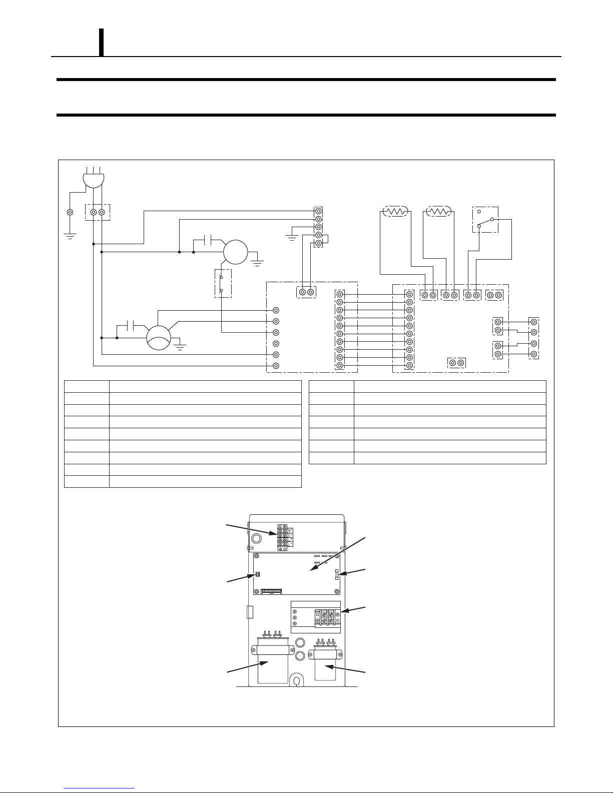
5.1 Circuit Diagram and Control Box
I002238
Relay Board Fuse
Relay Board
Terminal Block
Fan Capacitor
Dip Switch
Compressor
Capacitor
TB2
TB1
AC 115 V 1φ60 Hz
AP
G
G
G
HI
LO
MC
CN RTH THS DS
CB
TB2
L-
J106
J108
J105
J101 J102 J103 J104
J201 L+
E-
E+
3
2
1
Jumper
Line
MF
IOLF
12
CF
CC
12
G
G
TR
J9
J8
RB
J6
J5
J4
J3
J2
J1
AP
TB1
TB2
CB
RB
MF
MC
CF
CC
Attachment Plug
Terminal Block
Terminal Block
Control Board
Relay Board
Fan Motor
Compressor Motor
Capacitor for Fan Motor
Capacitor for Compressor
IOLF
OLC
DS
THS
RTH
G
CN
Inner Overload Relay of Fan Motor
Inner Overload Relay of Compressor
Full Drain Warning Switch
Freeze Protection Thermistor
Room Thermistor
Grounding
Connector for Option Drain Pump
TB1
Terminal Block
(Signal Connections)
1
2
OLC
Other manuals for OFFICE PRO 18
2
Table of contents
Popular Wine Cooler manuals by other brands


U-Line
U-Line U-3045RDCINT-00B User guide & service manual

Haier
Haier WS GA Series user manual

Rosehill Wine Cellars
Rosehill Wine Cellars 6ft Premier Cru Kit Rack Assembly instructions

Cuisinart
Cuisinart Private Reserve CWC-900 Instruction booklet

Avintage
Avintage DIVA Evolution 180 user guide

CASO DESIGN
CASO DESIGN WineComfort 66 black Original operating manual


