MPI InfoPrint 6700 Series User manual


Second Edition (September 2009)
This edition applies to the Online Data Validator (DB15) for the InfoPrint 6700 Series Thermal
Printer and replaces the following publication:
InfoPrint 6700 Series Thermal Printer: Online Data
Validator (DB15) User’s Manual,
G550-1173-00.
You can send comments by e-mail to printpub@infoprint.com or by mail to:
InfoPrint Solutions Company
6300 Diagonal Hwy 002J
Boulder, CO 80301-9270
U.S.A.
This product is or contains commercial computer software and commercial computer software
documentation developed exclusively at private expense. As specified in Federal Acquisition
Regulation 12.212 in the case of civilian agencies and Defense Federal Acquisition Regulation
Supplement 227.7202 in the case of military agencies, use, duplication and disclosure by agencies
of the U.S. Government shall solely be in accordance with the accompanying International
Program License Agreement in case of software products and in accordance with the licensing
terms specified in the product’s documentation in the case of hardware products.
© Copyright InfoPrint Solutions Company 2009. All rights reserved.
Before using this information and the product it supports, read the information in “Notices” on
page 77.
Note:
Visit our home page at: http://www.infoprint.com
Internet
Mantenimiento Periféricos Informáticos C/Canteras, 15 28860 Paracuellos de Jarama (Madrid) Tel: 00 34 917481604 Web: https://mpi.com.es/

1 Installation Instructions ......................................... 7
Overview................................................................................................ 7
Safety Notices........................................................................................ 9
Installation and Removal ..................................................................... 10
Prepare The Printer....................................................................... 10
Install The Ferrite .......................................................................... 10
Install The Validator ...................................................................... 17
Attach The Power/Data Cable....................................................... 20
Restore The Printer To Operation ....................................................... 22
Enable The Validator ........................................................................... 22
Adjust The Scanning Beam ................................................................. 23
Continuous, Tear-Off, and Tear-Off Strip...................................... 23
Peel-Off Media Handling Mode ..................................................... 24
Cut Media Handling Mode............................................................. 25
Scanning Beam Vertical Alignment............................................... 27
Scanning Beam Skew Adjustment (R40 and R60 models only) ... 27
Shifting The Scanning Beam ............................................................... 28
Calibration............................................................................................ 29
Bar Code Validation Demo Page .................................................. 31
2 Operation ............................................................ 33
Basic Validator Setup .......................................................................... 33
VALIDATOR Menu........................................................................ 34
Configuring The Validator .................................................................... 37
Enabling And Disabling The Validator........................................... 37
Validator Reporting ....................................................................... 38
Validator Statistics......................................................................... 41
Defining Validator Options ............................................................ 41
Advanced Validator Options.......................................................... 45
General Process For Barcode Analysis ........................................ 59
Operation ............................................................................................. 60
Print Speed Limits ......................................................................... 60
On-Demand Printing ..................................................................... 62
Table of Contents
Mantenimiento Periféricos Informáticos C/Canteras, 15 28860 Paracuellos de Jarama (Madrid) Tel: 00 34 917481604 Web: https://mpi.com.es/

Bar Code Failures................................................................................ 63
Bad Bar Code Error Detection ...................................................... 63
Missing Bar Code Error Detection................................................. 63
Validator Action/Error Action ......................................................... 64
Error Messages............................................................................. 69
Troubleshooting................................................................................... 73
Maintenance ........................................................................................ 75
Notices ................................................................ 77
Product Recycling and Disposal.......................................................... 79
Communication Statements................................................................. 80
Mantenimiento Periféricos Informáticos C/Canteras, 15 28860 Paracuellos de Jarama (Madrid) Tel: 00 34 917481604 Web: https://mpi.com.es/

7
1Installation Instructions
Overview
The online data validator (ODV) is an external bar code scanning device
attached above the paper exit of the printer. When activated, it scans the
printed output looking for bar codes. When it finds a bar code, it determines
what type of bar code it is and monitors the bar code quality as it passes
through the scan area.
After the entire bar code has passed under the scanning beam, the validator
grades the bar code and sends a report to the printer. How the printer
responds is determined by the validator settings, explained in “Configuring
The Validator” on page 37.
Operational Parameters
The design parameters of the validator are as follows:
•The validator can track the performance of up to four horizontal bar codes
at one time.
•The validator requires a minimum distance of 1/2 inch or 20 times the
minimum element width (x-dimension), whichever is greater, between bar
codes.
•The validator recognizes the following linear, picket fence bar codes:
Codabar, Code 39, Code 93, Code 128, Interleaved 2 of 5, and UPC/
EAN.
•The validator can also evaluate PDF 417 bar codes. For PDF 417
Limited, the validator works best with security level 5 or higher, using the
current default printer settings for Defects Percentage, Percent Decode,
and Decodeability. For lower security levels, lower the Defects
Percentage to 5% to enable checking for bar code damage.
•Stacked, 2D, and vertical (ladder) bar codes are not supported.
•Bar codes must have a minimum x-dimension of 10 mil (0.010 inch) to be
recognized by the full width of the scanning beam. The validator can
recognize bar x-dimension as narrow as 6.6 mil (0.0066 inch) for 300 dpi
printers, and 10 mil (0.010 inch) for 203 dpi printers. The validator cannot
recognize x-dimensions smaller than 6.6 mil (0.0066 inch) or larger than
40 mil (0.040 inch).
Mantenimiento Periféricos Informáticos C/Canteras, 15 28860 Paracuellos de Jarama (Madrid) Tel: 00 34 917481604 Web: https://mpi.com.es/

8
Chapter 1 Overview
Refer to Table 1 for the minimum x-dimension requirements for each printer
size of a 300 dpi printer.
Tools And Materials You Will Need
•
InfoPrint 6700 Series Thermal Printer User’s Manual
•Static wrist strap*
•2.5 mm hex key*
•#2 Phillips Screwdriver*
Parts List
•3 mm hex key
•Validator
•Validator bracket and mounting screws
•Cable ties, black
•Bar code calibration card
•Ferrite*
•Cable assembly*
•Wire saddle*
•Grommet*
•ODV Interface PCBA (used for 6700 Energy Star models only)
* Only for a field installation
Table 1: Minimum X-Dimension and Beam Width for
a 300 dpi Printer
Printer Size Beam Width Minimum
X-Dimension
4 inch 4.5 inches 6.6 mil
6 inch 6.5 inches 10 mil
8 inch 8.5 inches 13 mil
Mantenimiento Periféricos Informáticos C/Canteras, 15 28860 Paracuellos de Jarama (Madrid) Tel: 00 34 917481604 Web: https://mpi.com.es/
9
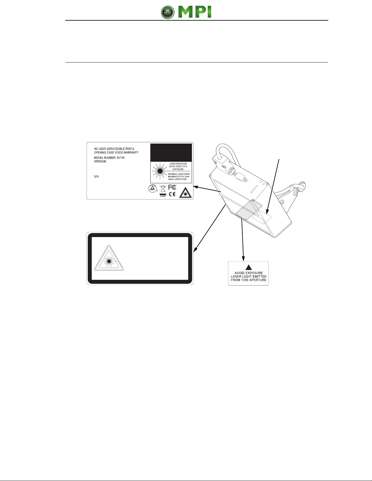
Safety Notices
The validator is a Class 2 laser product. The following notices apply at all
times when the printer is powered on and the validator is active:
WARNING
Class 2 laser light. Do not stare into the laser beam or a reflected image
of the laser beam.
WARNING
Using controls, making adjustments, or performing procedures other
than those specified herein may result in hazardous radiation exposure.
Figure 1. Safety Warnings
183453a
CAUTION
MADE IN U.S.A. by Printronix
CANADA ICES/NMB-003 CLASS/CLASSE B
Scan Distance:
CAUTION
LASER RADIATION. DO NOT STARE INTO BEAM
CLASS 2 LASER PRODUCT
ATTENTION
RAYONNEMENT LASER. NE PAS REGARDER DANS LE FAISCEAU.
APPARELL À LASER DE CLASSE 2
ACHTUNG
LASERSTRAHLUNG NICHT IN DEN STRAHL BLICKEN
LASER KLASSE 2
636-680NM, LASER DIODE
MAXIMUM OUTPUT 4.2MW
IEC60825-1:1993+A1+A2
Note: This is the
laser exit window.
Mantenimiento Periféricos Informáticos C/Canteras, 15 28860 Paracuellos de Jarama (Madrid) Tel: 00 34 917481604 Web: https://mpi.com.es/

10
Chapter 1 Installation and Removal
Installation and Removal
This section describes how to install the validator. To remove the validator,
reverse the steps of this procedure.
Prepare The Printer
1. Set the printer power switch to O (Off).
WARNING
Always unplug the printer power cord from the printer or power outlet
before doing any installation procedure. Failure to remove power could
result in injury to you and damage the equipment. You will be instructed
when to apply power.
2. Unplug the printer power cord from the printer or the AC power source.
Factory Installation
If your printer has a factory installed validator, the ferrite, cable, wire saddle,
and grommet have already been installed. Go to “Install The Validator” on
page 17.
Field Installation
If you are doing a field installation, you must install the ferrite, cable, wire
saddle, and grommet. Go to “Install The Ferrite” on page 10.
Install The Ferrite
1. Loosen the two captive screws securing the top of the frame side cover.
(Figure 2.)
2. Tilt the frame side cover back from the top and lift it until the tabs along
the lower edge disengage from the slots in the printer frame.
Figure 2. Removing the Frame Side Cover
183454a
ETHERNET
PARALLEL
USB
GPI0
RS232
STATUS
DEBUG
Captive
Screw (2)
Frame Side Cover
Mantenimiento Periféricos Informáticos C/Canteras, 15 28860 Paracuellos de Jarama (Madrid) Tel: 00 34 917481604 Web: https://mpi.com.es/

Install The Ferrite
11
Figure 3. Locating the Ferrite Position on the Power/Data Cable
3. Stretch the Power/Data cable out straight on a flat surface.
4. Measure back 20.0 ± 0.5 inches from the DB15 connector and mark the
cable with a pencil line. (Figure 3.)
Figure 4. Routing the Power/Data Cable
183455a
±
20.0 0.5
inches
DB15 Connector
183456a
P10 Connector
Plastic Plug
Frame Opening
Mantenimiento Periféricos Informáticos C/Canteras, 15 28860 Paracuellos de Jarama (Madrid) Tel: 00 34 917481604 Web: https://mpi.com.es/

12
Chapter 1 Installation and Removal
CAUTION
To prevent electrostatic damage to electronic components, always wear
a properly grounded static wrist strap when you handle circuit boards.
5. Put on a static wrist strap and ground it to an unpainted part of the printer
frame. Touch the frame with the hand wearing the wrist strap.
6. Raise the media cover and remove the plastic plug from the frame
opening.
7. Gently press the small wires of the P10 connector end of the power/data
cable against the connector and route the connector through the frame
opening. (Figure 4.)
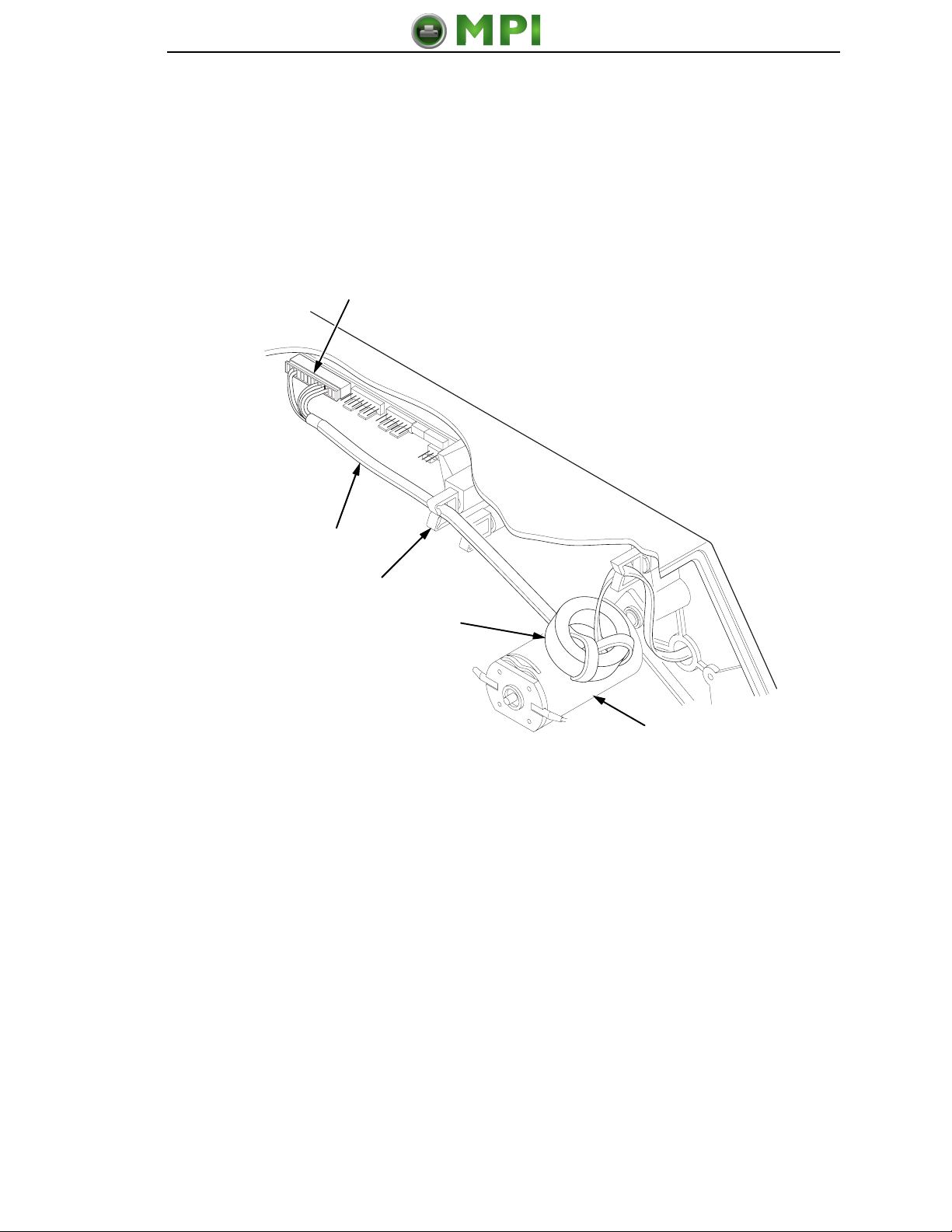
Figure 5. Wrapping the Power/Data Cable Around the Ferrite
8. Using the P10 connector end of the power/data cable, insert the cable
through the ferrite. (Figure 5.)
9. Wrap the power/data cable around the ferrite twice.
10. Adjust the position of the ferrite so that the length from the ferrite to the
DB15 connector is 20 ± 0.5 inches.
183457a
P10 Connector
(to controller board)
Ferrite
Pencil Line
Mantenimiento Periféricos Informáticos C/Canteras, 15 28860 Paracuellos de Jarama (Madrid) Tel: 00 34 917481604 Web: https://mpi.com.es/

Install The Ferrite
13
Figure 6. Inserting the Wire Saddle Into the Frame Boss
11. Insert the wire saddle into the frame boss. (Figure 6.)
183458a
Frame Boss
Wire Saddle
Mantenimiento Periféricos Informáticos C/Canteras, 15 28860 Paracuellos de Jarama (Madrid) Tel: 00 34 917481604 Web: https://mpi.com.es/
14
Chapter 1 Installation and Removal
Figure 7. Routing the Power/Data Cable From the Hole in the Frame Wall
12. Route the power/data cable through the wire saddle.
Figure 8. Adding the Grommet to the Power/Data Cable
183459a
Ferrite
Wire Saddle
Frame
Opening
183460a
Split
Grommet
Power/Data Cable
(approximately
17 inches exposed)
InsertedSplit
Grommet
(media side)
DB15
Connector
Mantenimiento Periféricos Informáticos C/Canteras, 15 28860 Paracuellos de Jarama (Madrid) Tel: 00 34 917481604 Web: https://mpi.com.es/
Install The Ferrite
15
13. On the media side of the printer, slide the split grommet onto the power/
data cable and insert it into the frame opening. (Figure 8.)
14. Inspect the power/data cable to ensure approximately 17 inches of cable
is exposed from the grommet to connect it to the validator.
NOTE: You will plug the power/data cable into the validator later.
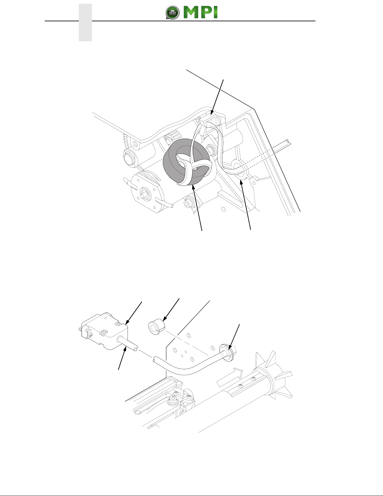
Figure 9. Position the Ferrite
15. On the electronics side of the printer, position the ferrite on top of the
upper DC motor. (Figure 9.)
16. Route the power/data cable through the wire saddle as shown in Figure 9.
17. Plug the P10 connector end of the power/data cable into the J10
receptacle on the controller board.
NOTE: For 6700 Energy Star models see Figure 10 on page 16.
183461a
J10
Power/Data Cable
Ferrite
Upper
DC Motor
Wire Saddle
Mantenimiento Periféricos Informáticos C/Canteras, 15 28860 Paracuellos de Jarama (Madrid) Tel: 00 34 917481604 Web: https://mpi.com.es/
16
Chapter 1 Installation and Removal
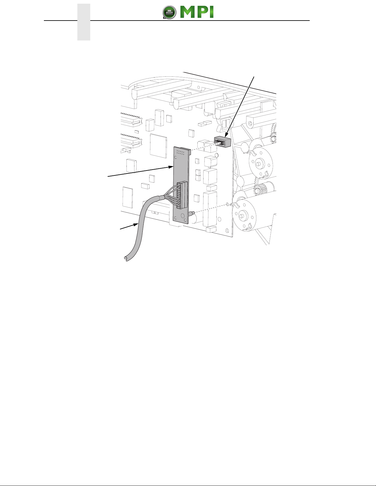
Figure 10. 6700 Energy Star Models – Plugging the Power/Data Cable into the ODV Interface
PCBA and then into the Controller Board
183658a
J10
Power/Data Cable
ODV Interface
PCBA
Mantenimiento Periféricos Informáticos C/Canteras, 15 28860 Paracuellos de Jarama (Madrid) Tel: 00 34 917481604 Web: https://mpi.com.es/
Install The Validator
17
Install The Validator
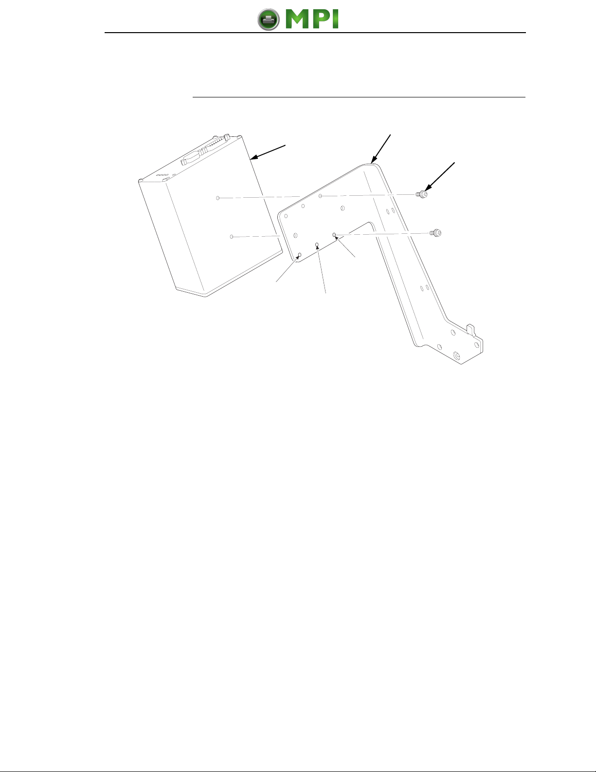
Figure 11. Attaching the Validator to the Bracket
1. Using two 6-32 Phillips head screws, attach the validator to the bracket as
shown in Figure 11.
2. Use the appropriate holes on the bracket, depending on the media width.
183339a
8”
Printer 6”
Printer
4”
Printer
Bracket
6-32Phillips
Screw (2)
Validator
Mantenimiento Periféricos Informáticos C/Canteras, 15 28860 Paracuellos de Jarama (Madrid) Tel: 00 34 917481604 Web: https://mpi.com.es/

18
Chapter 1 Installation and Removal
Figure 12. Positioning the Validator on the Bracket
1. Apply even pressure to the side of the validator as you tighten the screws
on the bracket as shown in Figure 12.
2. Make sure the validator is firmly seated against both screws to insure
proper beam alignment.
183340a
Mantenimiento Periféricos Informáticos C/Canteras, 15 28860 Paracuellos de Jarama (Madrid) Tel: 00 34 917481604 Web: https://mpi.com.es/

Install The Validator
19
Figure 13. Attaching the Validator/Bracket Unit to the Printer
3. Face the front of the printer while installing the validator/ bracket unit.
4.
Using four M4x10mm screws, attach the validator/bracket unit to the
printer frame as shown in Figure 13.
5. Tighten the four screws finger tight. You will adjust the
validator/bracket unit in a later step using the 3mm hex key (provided).
183341a
Validator/Bracket Unit
M4x10mm
Screw (4)
Mantenimiento Periféricos Informáticos C/Canteras, 15 28860 Paracuellos de Jarama (Madrid) Tel: 00 34 917481604 Web: https://mpi.com.es/
20
Chapter 1 Installation and Removal
Attach The Power/Data Cable
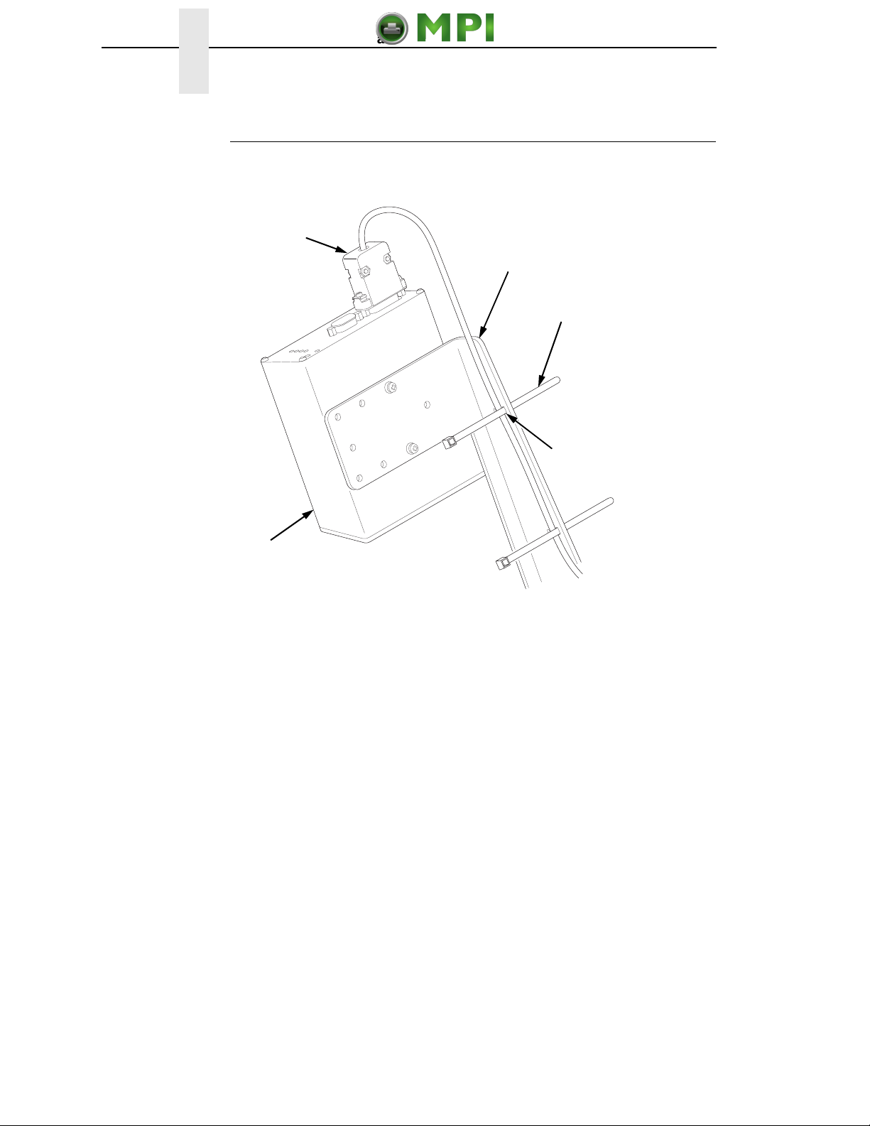
Figure 14. Attaching the Power/Data Cable
1. Plug the DB15 connector end of the power/data cable into the validator.
2. Route the power/data cable along the inside of the bracket, as shown in
Figure 14.
3. Route a tie wrap from the inside of the bracket through the first upper slot
as shown in Figure 14, keeping the power/data cable underneath the tie
wrap.
183342a
Tie Wrap (2)
Power/Data Cable
DB15 Connector
Validator
Bracket
First Upper
Slot
Mantenimiento Periféricos Informáticos C/Canteras, 15 28860 Paracuellos de Jarama (Madrid) Tel: 00 34 917481604 Web: https://mpi.com.es/
This manual suits for next models
1
Table of contents
Other MPI Printer Accessories manuals


