MPS EV2681B-S-00A User manual

The Future of Analog IC Technology
EV2681B-S-00A
CC/CV Controller
with Full Protection and Indication
EV2681B-S-00A Rev. 1.0 www.MonolithicPower.com 1
8/4/2016 MPS Proprietary Information. Patent Protected. Unauthorized Photocopy and Duplication Prohibited.
© 2016 MPS. All Rights Reserved.
DESCRIPTION
The MP2681B is a highly integrated Li-ion or Li-
polymer switch-mode battery-charge controller
with full protection and status indication. This
part integrates a precision voltage reference
and charge status indications suitable for AC
adapter input and cradle charger applications.
The MP2681B detects automatically the battery
cell through a battery ID resistor and regulates
the battery voltage according to the
corresponding cell configurations: 3S, 4S, and
5S. Then, the AC adapter output is regulated
automatically according to the chosen battery
configuration. Additionally, if the battery pack
does not have an ID resistor, the charge
termination voltage can be configured by setting
a dedicated voltage to the ID pin, according to
the pre-set VID values representing the battery
configuration. The MP2681B charges the
battery in three phases: pre-charge, constant
current and constant voltage. Charge is
terminated when the current reaches a
minimum set level. An internal charge timer
provides safety back-up. The MP2681B
provides a fixed pre-charge mode for deeply-
discharged batteries and safety features that
include battery temperature monitoring, NTC
control, charge time-out, and fault control.
ELECTRICAL SPECIFICATION
Parameter Symbol Value Units
Input Voltage VACIN 85V-220V V
Battery Voltage VBATT 0 to 21 V
VDD Voltage VSYS 5 to 30 V
Charge Current ICHG 0-4 A
FEATURES
Constant Voltage and Constant Current
Control
Pre-Charge Mode for Deep-discharged
Battery
Automatic Battery Cell Detection
Two 1MHz Bandwidth Operational Amplifier
Output Connected with OR Logic
Wide Input Voltage Range: 5V to 30V
Auto-Recharge
Charge On/Off Control
Programmable Internal Timer
Battery Temperature Monitoring
Charge Status Indication
Power Line Fault Detection
Over Temperature Protection
APPLICATIONS
Battery Charger for Portable Tools
Standalone Fast Charger
A
ll MPS parts are lead-free, halogen free, and adhere to the RoHS directive. Fo
r
MPS green status, please visit MPS website under Quality Assurance. “MPS”
and “The Future of Analog IC Technology” are Registered Trademarks o
f
Monolithic Power Systems, Inc.

EV2681B-S-00A —CC/CV CONTROLLER WITH FULL PROTECTION EVAL. BOARD
EV2681B-S-00A Rev. 1.0 www.MonolithicPower.com 2
8/4/2016 MPS Proprietary Information. Patent Protected. Unauthorized Photocopy and Duplication Prohibited.
© 2016 MPS. All Rights Reserved.
EV2681B-S-00A EVALUATION BOARD
(L x W x H)
(12.2cm x 7.5cm x 0.16cm)
Board Number MPS IC Number
EV2681B-S-00A MP2681B

EV2681B-S-00A —CC/CV CONTROLLER WITH FULL PROTECTION EVAL. BOARD
EV2681B-S-00A Rev. 1.1 www.MonolithicPower.com 3
8/4/2016 MPS Proprietary Information. Patent Protected. Unauthorized Photocopy and Duplication Prohibited.
Preliminary Specifications Subject to Change © 2016 MPS. All Rights Reserved.
EVALUATION BOARD SCHEMATIC

EV2681B-S-00A —CC/CV CONTROLLER WITH FULL PROTECTION EVAL. BOARD
EV2681B-S-00A Rev. 1.1 www.MonolithicPower.com 4
8/4/2016 MPS Proprietary Information. Patent Protected. Unauthorized Photocopy and Duplication Prohibited.
Preliminary Specifications Subject to Change © 2016 MPS. All Rights Reserved.
EV2681B-S-00A BILL OF MATERIALS
Qty RefDes Value Description Package Manufacturer Manufactuer_P/N
1 BD1 GBU406 Diode;600V;4A DIP Diodes GBU406
2 C1,C25 120μF Electrolytic Capacitor;
400V;Electrolytic; DIP Jianghai
1 C2 4.7nF
High Voltage
Capacitor;1000V DIP any any
1 C3 22μF Capacitor;50V DIP Rubycon 50YXM22MEFC5*11
1 C4 47μF Electrolytic Capacitor;
25V;Electrolytic; DIP Jianghai CD28L-25V47
1 C5 0.1μF Ceramic Capacitor;
25V;X7R; 0603 Yageo CC0603KRX7R8BB104
1 C6 47nF
Ceramic Capacitor;
50V;X7R; 0603 muRata GRM188R71H473KA61D
1 C7 1nF
Ceramic Capacitor;
50V;X7R; 0603 muRata GRM188R71H102KA01D
1 C8 22pF
Ceramic Capacitor;
50V;C0G; 0603 muRata GRM1885C1H220JA01D
1 C9 470pF
Ceramic Capacitor;
1000V;U2J; 1206 muRata GRM31B7U3A471JW31L
3 C10,
C11, C12 680μF Electrolytic Capacitor;
35V;Electrolytic; DIP Jianghai CD287-35V680
1 C13 470μF Electrolytic Capacitor;
35V;Electrolytic DIP Jianghai CD263-35V470
1 C14 10μF Ceramic Capacitor;
50V;X7R 1210 Murata GRM32ER71H106KA12L
2 C15, C16 2.2μF Ceramic Capacitor;
50V;X7R; 1206 muRata GRM31CR71H225KA88L
3 C17,
C18, C19 100nF Ceramic Capacitor;
50V;X7R; 0603 muRata GRM188R71H104KA93D
1 C20 2.2μF Ceramic Capacitor;
16V;X7R; 0805 TDK C2012X7R1C225K
1 C21 1nF
Ceramic Capacitor;
50V;C0G; 0603 muRata GRM1885C1H102JA01D
1 CX1 0.47μF Film Capacitor;
275V;10% DIP Caili PX474K3ID42L270D9R
1 CY1 2.2nF Capacitor;4000V;20% DIP Hongke JN12E222MY02N
3 D1, D2,
D4 1N4007 Diode;1000V;1A DO-41 Diodes 1N4007
1 D3
MBR2015
0FCT Diode;150V;20A TO-
220AB Xutong MBR20150FCT
1 D5 FR107 Diode;1000V;1A DO-41 Diodes FR107
1 D6 1N4148W Diode;75V;0.15A; SOD-
123 Diodes 1N4148W
1 F1 SS-5-
3.15A Fuse;250V;3.15A DIP
COOPER
BUSSMANN SS-5-3.15A
1 L1 3.3μH Inductor;3.3μH;25m;4A DIP Wurth 7447462033
1 LED1 LED Green LED; DIP F3D02HG-1A
1 LED2 LED Red LED; DIP F3D02R-4A

EV2681B-S-00A —CC/CV CONTROLLER WITH FULL PROTECTION EVAL. BOARD
EV2681B-S-00A Rev. 1.1 www.MonolithicPower.com 5
8/4/2016 MPS Proprietary Information. Patent Protected. Unauthorized Photocopy and Duplication Prohibited.
Preliminary Specifications Subject to Change © 2016 MPS. All Rights Reserved.
EV2681B-S-00A BILL OF MATERIALS
(continued)
Qty RefDes Value Description Package Manufacturer Manufactuer_P/N
1 LX1 150μH Inductor;150μH;
45m; 3A DIP Emei TP4U150-00
1 LX2 33mH
Inductor;33mH;
210m;3A DIP Wurth 744825433
1 Q1
IPP65R28
0E6
Mosfet;700V;
0.28/10V;45;39 TO220 IPP65R280E6
1 Q2
MMBTA06
LT1G Transistor;80V;0.5A; SOT-23 Diodes MMBTA06LT1G
2 Q3, Q4 AM4417P P-Channel Mosfet;-
60V;23;46;9.3 SO-8 Analog Power AM4417P
1 Q5 S8050 Transistor;25V;0.5A; SOT-23 Changdian S8050
1 R1 33kΩResistor;5%;1/4W 1206 Royalohm 1206F3302T5E
2 R2, R3 150kΩResistor;5%;1W DIP any any
1 R4 20ΩFilm Resistor;5%;1/4 1206 1206J0200T5E
2 R5,R7 10kΩFilm Resistor;1% 1206 Yageo RC1206FR-0710K
2 R6 0ΩResistor;1%;
1/4W;1206 1206 Yageo RC1206FR-070RL
1 R8 20ΩResistor;1%;1/4W DIP any any
1 R9 20ΩResistor;5%;1/8W; 0805 Yageo RC0805JR-0720RL
1 R10 20kΩFilm Resistor;5%;1/4W 1206 LIZ CR1206J40203G
4 R11,R12,
R13, R14 1ΩFilm Resistor;1% 1206 Yageo RC1206FR-071RL
1 R15 1kΩResistor;1% 1206 Yageo RC1206FR-071KL
2 R16, R17 51ΩResistor;1% 1206 Yageo RC1206JR-0751RL
4 R18,R27,
R28, R30 10kΩFilm Resistor;1%; 0603 Yageo RC0603FR-0710KL
1 R19 50mΩFilm Resistor;1%; 2512 Yageo RL2512FK-070R05L
2 R20 300mΩ*2 Resistor;1% 2512 Yageo RL2512FK-070R3L
2 R21,R40 2kΩResistor;1% 0603 Yageo RC0603FR-072KL
1 R22 1kΩFilm Resistor;1% 0603 Yageo RC0603FR-071KL
1 R23 1.5kΩFilm Resistor;1%; 0603 Yageo RC0603FR-071K5L
1 R24 2.2kΩFilm Resistor;1%; 0603 Yageo RC0603FR-072K2L
1 R25 470 Film Resistor;1%; 0603 Yageo RC0603FR-07470RL
2 R26 18kΩResistor;1%;1/10W; 0603 Yageo RC'0603FR-0718KL
1 R29 20kΩResistor;1%;1/10W; 0603 Royalohm 0603F2002T5E
2 R31,R32 1.8kΩFilm Resistor;5% 0603 LIZ CR0603JA0182G
2 R33,R34 6.8kΩFilm Resistor;1%; 0603 Yageo RC0603FR-076K8L
2 R35,R36 15kΩFilm Resistor;1%; 0603 Yageo RC0603FR-0715KL
2 R37, R38 1kΩResistor;1%; 0603 Royalohm 0603F1001T5E
1 R39 10kΩFilm Resistor;5%; 0805 Yageo RC0805JR-0710KL
2 R41, R42 1M Film Resistor;1%; 1206 Yageo RC1206FR-071ML
1 RT1 5ΩResistor DIP Xinshun 5D2-10LC
1 T1 434μH EER28,Np:Np_aux:Ns
=57:29:12 DIP Emei FX0370
1 U1 HFC0400 Offline Regulator SOIC8-7 MPS HFC0400HS

EV2681B-S-00A —CC/CV CONTROLLER WITH FULL PROTECTION EVAL. BOARD
EV2681B-S-00A Rev. 1.1 www.MonolithicPower.com 6
8/4/2016 MPS Proprietary Information. Patent Protected. Unauthorized Photocopy and Duplication Prohibited.
Preliminary Specifications Subject to Change © 2016 MPS. All Rights Reserved.
EV2681B-S-00A BILL OF MATERIALS
(continued)
Qty RefDes Value Description Package Manufacturer Manufactuer_P/N
1 U2 MP2681B CC/CV Controller SOIC16 MPS MP2681BGS
1 U3 PC817A Photocoupler;1-Channel DIP Sharp PC817A
2 ZD1,
ZD3 BZT52C16 Zener Diode;
16V;5mA/500mW; SOD-123 Diodes BZT52C16
1 ZD2 P6KE170CA Diode;145V;1mA DO-15 Brightking P6KE170CA
2 ZD4,
ZD5 BZT52C30 Zener
Diode;30V;2mA/500mW; SOD-123 Diodes BZT52C30
4
BATT+,
BATT-,
ID, NTC
2.0 公针 {Package}
2 L, N 1.0 公针 {Package}

EV2681B-S-00A —CC/CV CONTROLLER WITH FULL PROTECTION EVAL. BOARD
EV2681B-S-00A Rev. 1.1 www.MonolithicPower.com 7
8/4/2016 MPS Proprietary Information. Patent Protected. Unauthorized Photocopy and Duplication Prohibited.
Preliminary Specifications Subject to Change © 2016 MPS. All Rights Reserved.
PRINTED CIRCUIT BOARD LAYOUT
Figure 1—Top Silk Layer
Figure 2—Bottom Layer

EV2681B-S-00A —CC/CV CONTROLLER WITH FULL PROTECTION EVAL. BOARD
NOTICE: The information in this document is subject to change without notice. Users should warrant and guarantee that third
party Intellectual Property rights are not infringed upon when integrating MPS products into any application. MPS will not
assume any legal responsibility for any said applications.
EV2681B-S-00A Rev. 1.0 www.MonolithicPower.com 8
8/4/2016 MPS Proprietary Information. Patent Protected. Unauthorized Photocopy and Duplication Prohibited.
© 2016 MPS. All Rights Reserved.
QUICK START GUIDE
The MP2681B is a voltage and current control IC integrated a precision voltage reference and charge
status indications, which is suitable for AC adapter input in the plug-in, cradle charger applications.
The device automatically detects the battery cell numbers through the battery ID resistor and regulates
the battery voltage according to the cell information: 3S, 4S, and 5S.
ID Resistor Detect Voltage Operation
Mode Battery
Spec VDD VBATT
Float
NTC
Float VID > 2.65V Sleep Mode No Battery 10.8V 0
NTC OK Default Mode 3S 12.44V 12.44V
1.8k 0.3V < VID < 0.7V
Automatic Mode
3S 12.44V 12.44V
6.8k 0.95V < VID < 1.6V 4S 16.59V 16.59V
15k 1.75V < VID <
2.65V 5S 20.74V 20.74V
Short VID < 0.3V Sleep Mode Unknown 10.8V 0
1. The charge current is set to 3A as the below formula in this board,
ICHG = 0.16/RS = 3A
Note: the reference voltage 0.16V has a +-15% variation.
2. In this board, there are two LEDs controlled by the MP2681B to work as smart charger status
indicators.
a) During the charging, LEDG flashes. At the same time, LEDR keeps off.
b) When the charging is finished, LEDG keeps on and LEDR is off.
c) When fault protection happens, LEDR flashes and LEDG keeps off.
3. Attached the AC Line (85~220V) terminals to L and N pins, respectively.
4. Connect the positive terminal of the battery to BATT+ pin, and connect the negative terminal of the
battery to BATT- pin, respectively.
5. Turn the power supply on. The board automatically startup.
6. The output voltage on this board is determined by voltage at the ID pin.
For more details, please apply the latest datasheet of the MP2681B for reference.
This manual suits for next models
1
Other MPS Controllers manuals
Popular Controllers manuals by other brands
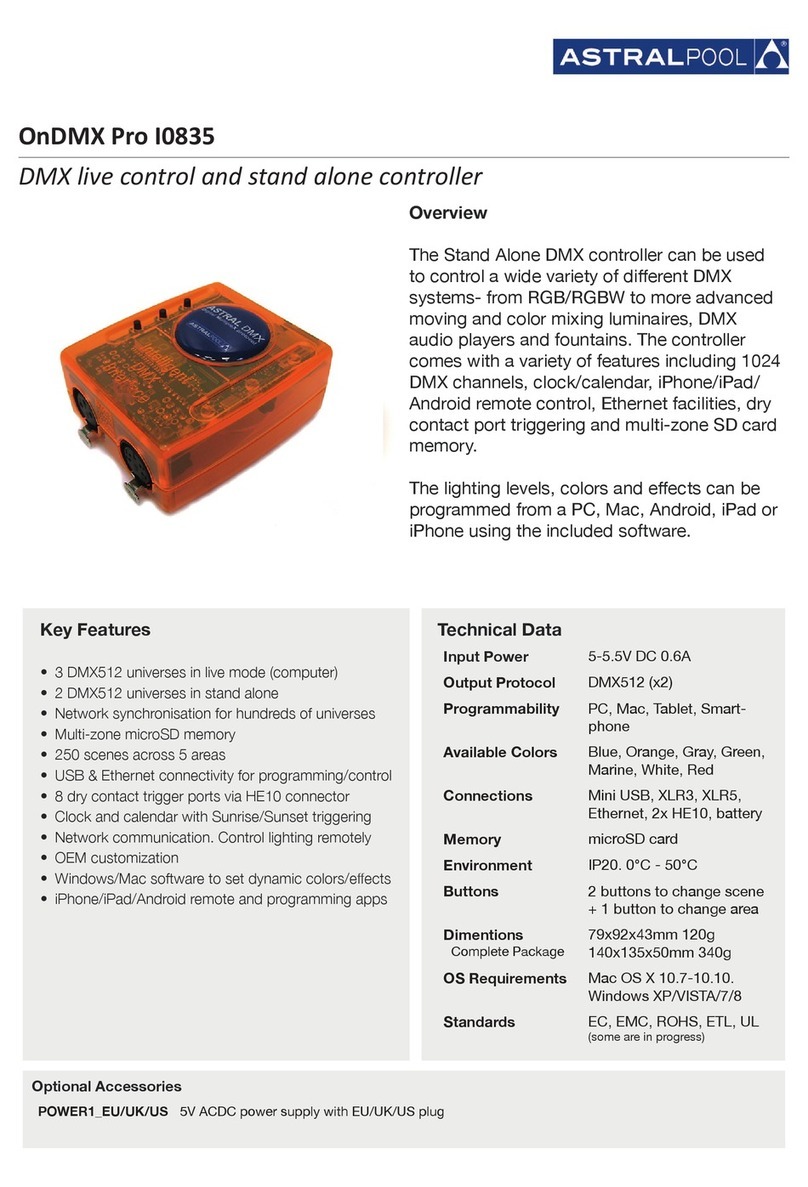
Astral Pool
Astral Pool IGNIA LIGHT DMX pro quick start guide
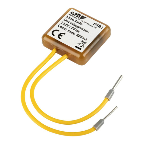
EQ3
EQ3 ESB1 operating manual
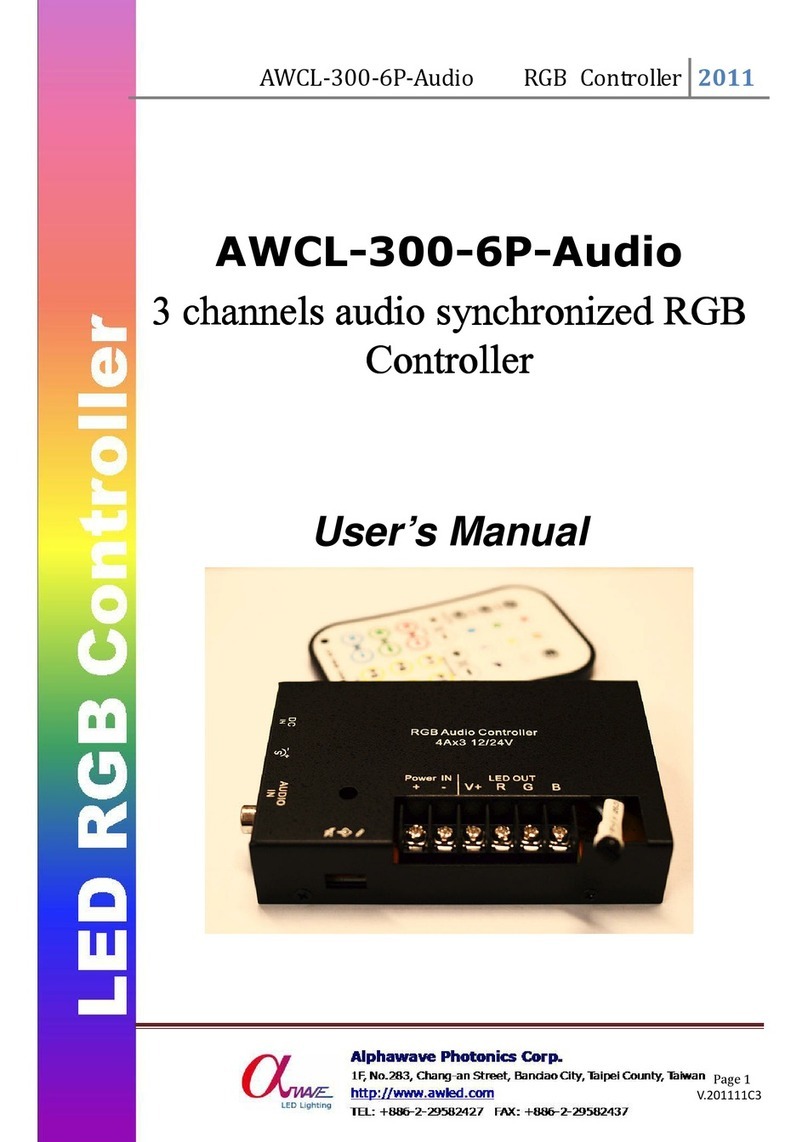
Alphawave Photonics
Alphawave Photonics AWCL-300-6P-Audio user manual
Southco
Southco EA-KC2-201 Instructions for Programming
IMG STAGE LINE
IMG STAGE LINE CU-4SMART instruction manual

Planet
Planet LN501 Quick installation guide
