MSD Ignition 8381 User manual

IMPORTANT: Due to the number of applications and years that the LT-1 Distributor is used on, it is highly
recommended to have the Service Manual for your vehicle during this installation.
IMPORTANT NOTES BEFORE INSTALLATION
Throughout its
course, the GM
LT-1engine used
two different
drive mecha-
nisms to con-
nect the cam to
the distributor.
Figure 1 shows
the drive for the
MSD PN 8381
Distributor. This
design is used in
the early model distributors. Make sure this is correct for your application.
Before removing the distributor it is recommended to mark the location of the rotor. This is to ensure
that the distributor and cam are indexed correctly prior to reassembly.
Be sure that the O-ring between the distributor cap and the housing is in place before installing the
cap. The O-ring must be stretched out, then installed onto the housing. It will shrink back to size.
TIMING INFORMATION
Since the timing of the MSD Pro-Billet Distributor can be adjusted, it is recommended that a timing indicator
and mark be fabricated prior to installing the distributor. This way, the timing can be recorded so the MSD
Distributor can be set to the same amount. From the factory,
the MSD Distributor is set to the OEM specs (one and a half
turns).
The MSD Distributor can alter the timing +/-6°, with a quar-
ter turn equalling 1° of timing. The adjusting screw has a soft
Loctite compound applied to it for a seal (Figure 2). Repeated
adjustments may loosen the screw. If this occurs, remove the
screw and apply Blue Loctite® to the threads. The screw can
safely be removed from the distributor.
Too much advance may cause detonation resulting in the
ECU retarding the timing through the engine’s knock sensor.
When adjusting the timing, take note that the ECU varies
the timing at an idle. It is recommended to bring the engine
rpm up to 1,500 - 2,000 when setting the timing.
MSD Pro-Billet LT-1 Distributor
'93-'94 F-Body, '92-'94 Corvette, '92-'94 Full Size
PN 8381
Parts Included:
1 - Distributor
1 - Cap
1 - Rotor
1 - Isolator
2 - Rotor Screws
1 - O-ring
3 - 1/4-20 x 2" Socket Head Cap Screws
5 - 8-32 x 0.5" Phillips Screws
1 - Vacuum Line Assembly
1 - Removal Tool
Figure 2 Adjusting the Timing.
Figure 1 The Drive Mechanism of the PN 8381 Distributor.
TIMING
ADJUSTER
CAMSHAFT
STOCK DISTRIBUTOR
INDEX
FLAT
SPOT
INDEX
MSD • WWW.MSDPERFORMANCE.COM • (915) 857-5200 • FAX (915) 857-3344
ONLINE PRODUCT REGISTRATION: Register your MSD product online and you’ll be entered in our
monthly 8.5mm Super Conductor Spark Plug Wire give-away! Registering your product will help if there
is ever a warranty issue with your product and helps the MSD R&D team create new products that you
ask for! Go to www.msdperformance.com/registration.

2 INSTALLATION INSTRUCTIONS
MSD • WWW.MSDPERFORMANCE.COM • (915) 857-5200 • FAX (915) 857-3344
DISASSEMBLY
1. Disconnect the negative battery cable.
2. Locate the radiator petcock and drain the coolant from
the system.
3. Disconnect the MAF, IAC, ICT and TPS sensors (Figure
3). Remove the air intake ducktwork.
4. Once the coolant is drained, remove the upper radiator
hose from the thermostat housing.
5. Loosen the three bolts that secure the crankshaft
pulley/hub assembly. Do not remove them entirely at
this time.
6. Remove the accessory drive belt by moving the spring
loaded idler pulley. Use caution as this pulley is spring
loaded! The belt will slide off the pulley system and the
idler pulley will settle beyond its installed position.
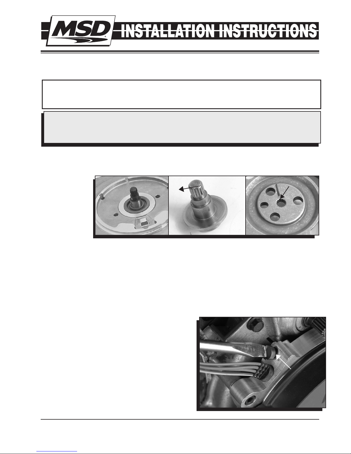
7. Once the belt is removed, proceed with removing the
pulley from the crankshaft hub by pulling the three
retaining bolts. A puller will be required (Figure 4).
8. It may be necessary to remove the cooling fan. This is
done by removing the four bolts and disconnecting the
wiring connection.
9. Disconnect the air pump power wires and remove the
air pump from its mounting brackets.
10. Disconnect the coolant temperature wiring sensor
located on the water pump.
11. Loosen the lower radiator hose clamp and the two
heater hose clamps at the water pump. Coolant will
generally still pour out of the hoses and water pump.
12. To remove the water pump, the power steering pump
may need to be removed. With a short extension, the
water pump bolt should be able to be accessed. There
are six water pump bolts. Once again, more coolant
may spill out.
13. At this point, you should be able to access the distributor
cap! Mark the location of each spark plug wire before
removing them.
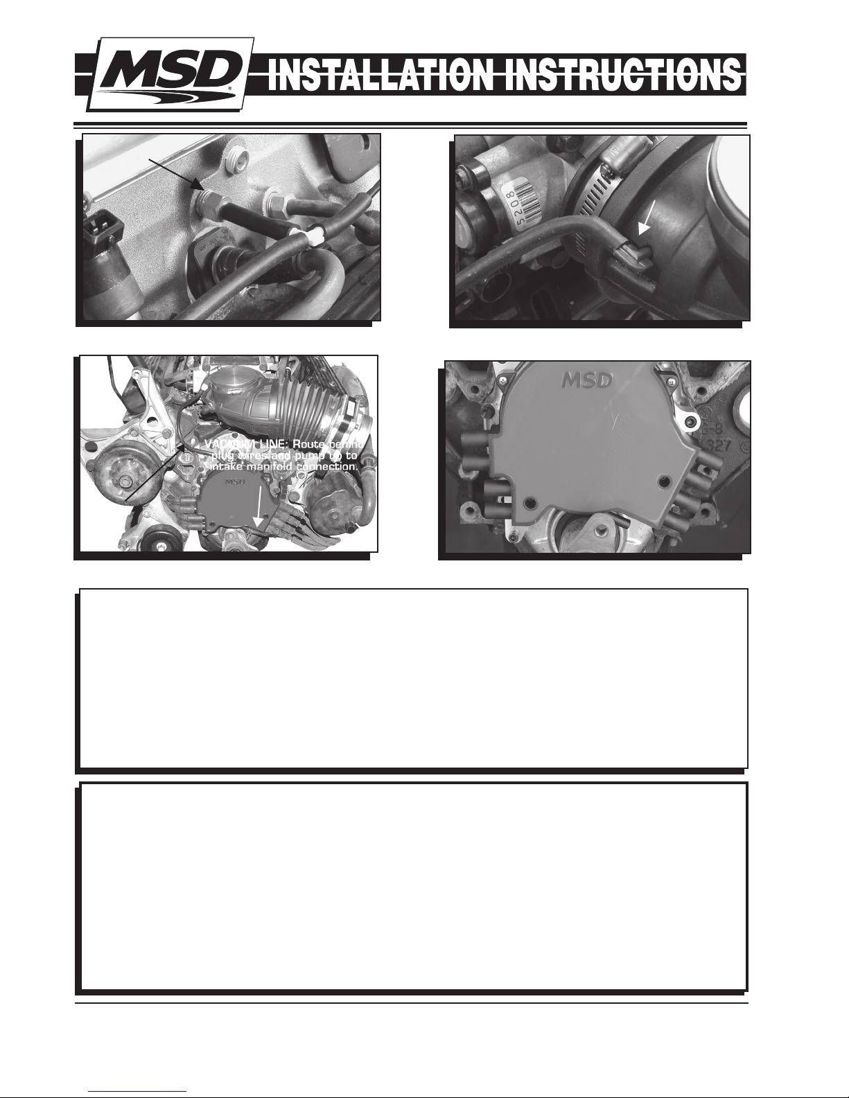
14. Remove the vacuum lines (if equipped) and the
distributor connector at the distributor and on the
passenger side of the intake manifold (Figure 5).
15. Using the supplied special tool and a 1/4" wrench,
Figure 6 Removing the Original Cap.
Figure 5 Disconnect the Distributor Connector.
Figure 7 Rotor Location.
MARK ROTOR
LOCATION
Figure 3 Disconnect TPS and IAC.
Figure 4 Removing the Hub.
IAC
TPS

INSTALLATION INSTRUCTIONS 3
MSD • WWW.MSDPERFORMANCE.COM • (915) 857-5200 • FAX (915) 857-3344
Figure 8 Removing the Distributor. Figure 9 Installing the New Distributor.
Figure 10 Installing the Seal and Cap.
Figure 11 Distributor Connector.
remove the four
screws that hold
the distributor cap
to the engine and
pull the cap off
(Figure 6). Mark
the location of the
rotor. This will help
ensure the proper
location of the new
distributor (Figure
7).
16. Remove the three
bolts that secure the distributor to the front cover
(Figure 8).
17. Notice the indexing pin on the camshaft (Refer to
Figure 1). Be sure to align the new distributor with the
pin on the cam. The rotor should come to rest in the
same location as it did in Figure 7.
18. Install the new Distributor (Figure 9). Use the supplied
socket head hex screws.
19. Install the square O-ring seal on the billet housing.
Use care not to twist or kink the seal.
20. Install the cap and tighten the five screws evenly.
21. Route the new wiring harness to the top of the intake
and plug in the connector (Figure 11).
VACUUM LINE ROUTING
The PN 8381 Distributor Kit is supplied with a vacuum
line kit that will aid in venting the distributor cap. One
hose assembly connects to a vacuum port on the intake
manifold while the other line connects to the air inlet going
into the throttle body.
1. Connect the long hose assembly to the lower vacuum
inlet of the MSD distributor cap (Figure 12). Use the
supplied clamp to secure the hose.
2. Route the vacuum line around the side of the engine
and up to the intake manifold. Splice into the hose
that connects just over the PCV valve (Figure 13). Also
note the check valve that is in-line. The black side of
the valve must face towards the vacuum source.
3. Connect the smaller vacuum line to the fresh air inlet
port on the top drivers' side of the distributor.
4. Locate the supplied 90° vacuum nipple. Using a 3/16"
drill bit, drill a hole in the air intake duct and install the
nipple (Figure 14). Make sure the barb goes through
and into the duct. Connect the line from the distributor
cap to this inlet. This line completes the fresh air
circulation through the distributor cap (Figure 15).
5. Install the spark plug wires ensuring they are routed
to the correct terminal (Figure 16) and reassemble.
Figure 12 Install the Lower Vacuum Line.
LOWER VACUUM
INLET
TO INTAKE
MANIFOLD
O-RING MUST
SEAT SQUARELY
AGAINST THIS
FLANGE.

Figure 16 Plug Wire Routing.
4
6
8
2
1
7
3
5
Figure 14 Installing the Fresh Air Line.
FRESH AIR
SOURCE
Figure 15 Fresh Air Hose Routing.
FRESH
AIR
INLET
VACUUM LINE: Route behind
plug wires and pump up to
intake manifold connection.
Figure 13 Connecting the Vacuum Source.
VACUUM
SOURCE
Limited Warranty
M
SD warrants this product to be free from defects in material and workmanship under its intended normal use*,
when properly installed and purchased from an authorized MSD dealer, for a period of one year from the date of
the original purchase. This warranty is void for any products purchased through auction websites. If found to be
defective as mentioned above, it will be repaired or replaced at the option of MSD. Any item that is covered under
this warranty will be returned free of charge using Ground shipping methods.
This shall constitute the sole remedy of the purchaser and the sole liability of MSD. To the extent permitted by
law, the foregoing is exclusive and in lieu of all other warranties or representation whether expressed or implied,
including any implied warranty of merchantability or fitness. In no event shall MSD or its suppliers be liable for special
or consequential damages.
*Intended normal use means that this item is being used as was originally intended and for the original application
as sold by MSD. Any modifications to this item or if it is used on an application other than what MSD markets the
product, the warranty will be void. It is the sole responsibility of the customer to determine that this item will work for
the application they are intending. MSD will accept no liability for custom applications.
Service
In case of malfunction, this MSD component will be repaired free of charge according to the terms of the warranty.
When returning MSD components for warranty service, Proof of Purchase must be supplied for verification. After
the warranty period has expired, repair service is based on a minimum and maximum fee.
All returns must have a Return Material Authorization (RMA) number issued to them before
being returned. To obtain an RMA number please contact MSD Customer Service at 1 (888) MSD-7859 or visit
our website at www.msdperformance.com/rma to automatically obtain a number and shipping information.
When returning the unit for repair, leave all wires at the length in which you have them installed. Be sure to include
a detailed account of any problems experienced, and what components and accessories are installed on the vehicle.
The repaired unit will be returned as soon as possible using Ground shipping methods (ground shipping is covered
by warranty). For more information, call MSD at (915) 855-7123. MSD technicians are available from 7:00 a.m. to
5:00 p.m. Monday - Friday (mountain time).
MSD • WWW.MSDPERFORMANCE.COM • (915) 857-5200 • FAX (915) 857-3344
© 2012 Autotronic Controls Corporation
FRM29722 Revised 01/12 Printed in U.S.A.
Table of contents
Popular Automobile Part manuals by other brands

Metra Electronics
Metra Electronics 99-9501B installation instructions

Edelbrock
Edelbrock Russell 672500 installation instructions

Vintage Air
Vintage Air 571064 manual

DAB
DAB BMH - BPH Series Instruction for installation and maintenance

Edelbrock
Edelbrock Turbocharger 15012 installation instructions

Intelligent Motion Systems
Intelligent Motion Systems IM1007 I/IE Hardware reference manual

Toyota
Toyota TUNDRA 2004 Technical service bulletin

Edelbrock
Edelbrock 3842 installation instructions

Havis
Havis C-VS-1900-INUT-PM installation instructions

Fisher
Fisher Chevrolet 13000 series Service manual

Edelbrock
Edelbrock Honda TRX300EX Instruction supplement

Skyjacker
Skyjacker C720MS installation instructions