Overview:
1013 is shipped out as a barebone. Some of the components are equipped while some are not. This
installation guide provides you with the information of notebook hardware setup. Before assembling your
notebook, please prepare installation tools and appropriate items. If you are not sure about the items,
please contact your dealer for more information.
Package check list:
Optional Hardware Devices:
HDD, Mini PCI WLAN card, CPU, Memory
Before installing the notebook
• The peripheral devices contained herein depend on your actual system configuration.
• Third-party trademarks and names are the properties of their respective owners.
• The information contained herein relevant to software and hardware are for reference only and in
accordance with actual system configuration. All information are subject to change without notice.
Warning!
• Ensure power is turned off and notebook battery is removed before you install any hardware
devices.
• Use a grounded wrist strap before handling computer components such as CPU, Memory, HDD,
mini-PCI Card, etc.
• Place components (CPU, Memory, HDD, mini-PCI Card, etc) on a grounded antistatic pad or on a
bed that comes with the components whenever the components are separated from the
notebook.
• If you have any difficulties in installing hardware devices, please contact your dealer for further
information.
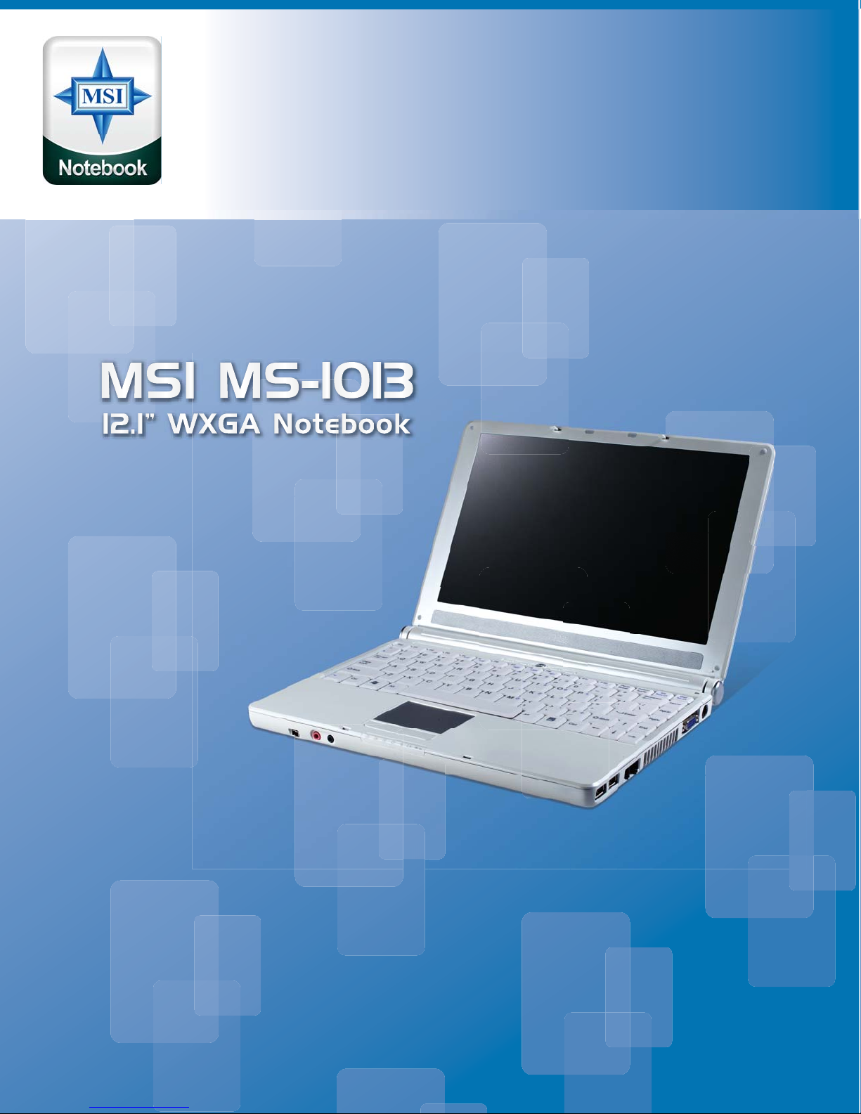
Open View
1. Cover latch
2. Display Panel
3. Quick Launch Buttons and Power button
4. Status LEDs
5. Keyboard
6. Touchpad
7. Stereo Speakers
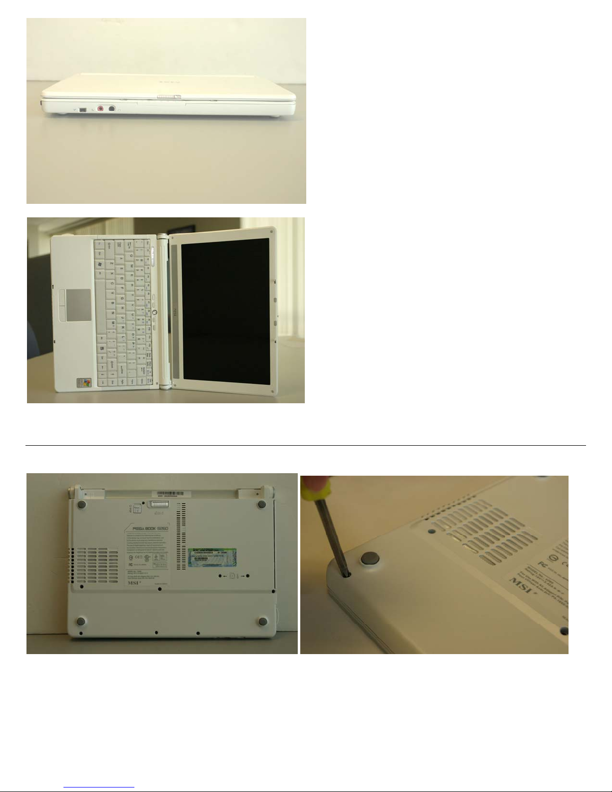
Bottom View
1. Battery Unlock Button
2. Battery Pack