MSI MSI9008 User manual

Page 2 MSI-9008 CellScale Multiplexer •User Guide
M E A S U R E M E N T S Y S T E M S I N T E R N A T I O N A L
Introduction ..................................................................................................... 3
Load Cell Connections .................................................................................... 3
Cable Parameters...................................................................................... 4
Load Cell Terminal Block ........................................................................ 5
CellScale Connections..................................................................................... 6
Multiplexer Cable 501802...................................................................... 6
Multiplexer Cable No.502305.................................................................. 8
Connecting One Multiplexer to CellScale ............................................... 8
Connecting Two Multiplexers to CellScale with One A/D ...................... 8
Connecting Two Multiplexers to CellScale with Two A/D’s ................... 9
Connecting Three Multiplexers to CellScale (Two A/D inputs reqd.) ..... 9
Connecting Four Multiplexers to CellScale (Two A/D inputs reqd.)....... 9
Software Setup............................................................................................... 10
Connecting One Multiplexer To CellScale ............................................ 10
Connecting Two Multiplexers To CellScale with One A/D ................... 10
Connecting Two Multiplexers To CellScale with Two A/D ................... 11
Connecting Three Multiplexers To CellScale (Two A/D inputs reqd.) .. 11
Connecting Four Multiplexers To CellScale (Two A/D inputs reqd.).... 12
Setting Up and Optimizing Readings..................................................... 13
Scan Order.............................................................................................. 13
Table of Contents Page
MSI-9008 CellScale Multiplexer •User Guide Page 3
M E A S U R E M E N T S Y S T E M S I N T E R N A T I O N A L
Introduction
The MSI-9008 Multiplexer is an input switching device that is digitally controlled by the MSI-9000 CellScale to switch
between eight possible input sources. The Multiplexer features an LED indicator designating which channel is currently
being switched to the output. The MSI-9000 CellScale controls the switching via three digital lines (Digital 0,1,2) on the
CellScale load cell connector. Excitation is passed from the control unit through the Multiplexer to each of the individual
input sources. At any one time, there are only two input sources being supplied power. All other inputs are turned off to
reduce power consumption.
The signal returned from the transducer (typically a load cell) is multiplexed or switched into a single channel input on the
CellScale (i.e. channel 1-x, 2-x, etc). This signal is then measured and processed according to the setup of the CellScale.
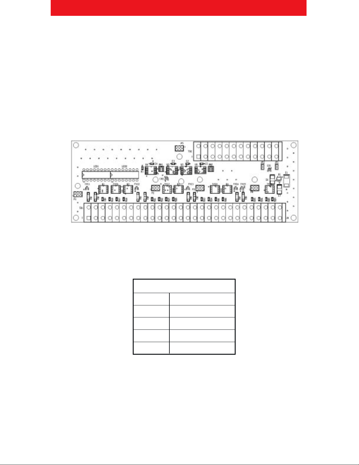
The following is an image of the circuit board. Note the spring-loaded terminal blocks for connecting the CellScale, load
cells, and additional Multiplexers.
Load Cell Connections
The MSI-9008 Multiplexer can control up to eight individual transducer inputs. These inputs can be taken directly from a
load cell or from junction/summing boxes combining multiple load cell signals. Devices such as load cells are connected
to the Multiplexer via four lines as summarized in the table below.
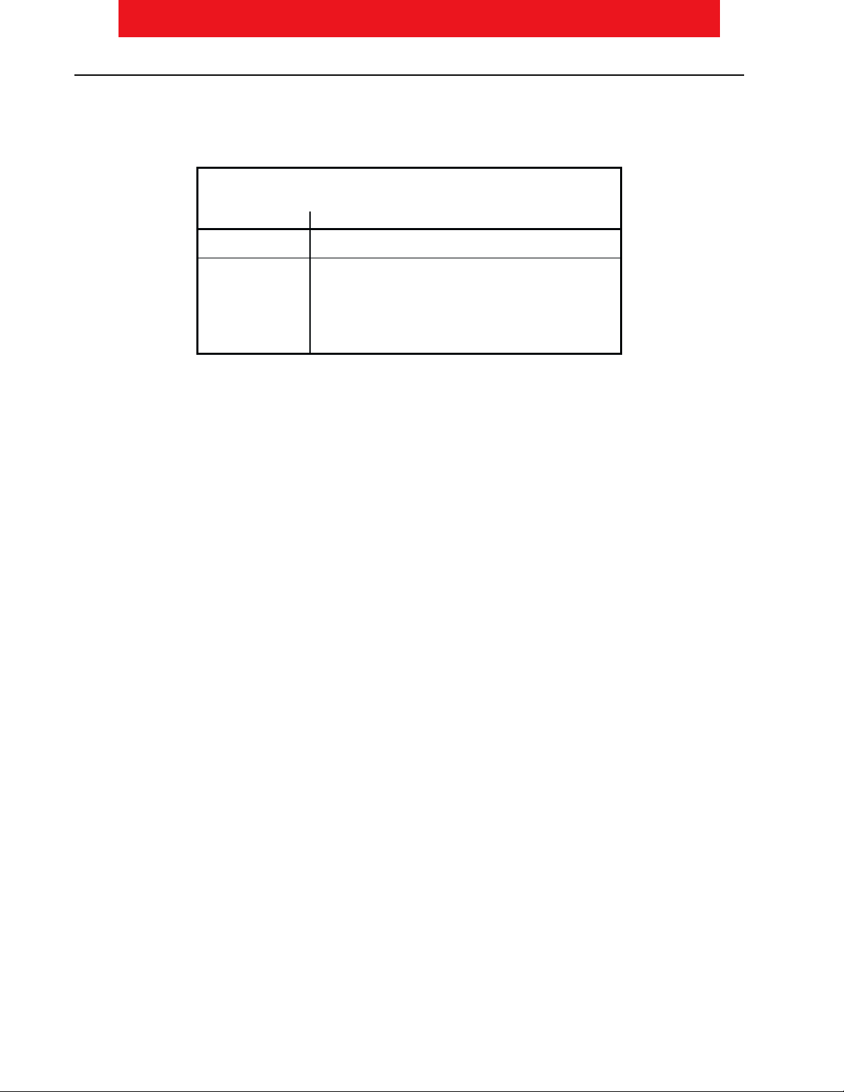
Load Cell Connections
Function Description
+EXC Positive Excitation
- EXC Negative Excitation
+ SIG Positive Signal
-SIG Negative Signal
An additional shield connection is provided for terminating cable shields. For details regarding wire color codes, please
refer to the load cell manufacturer’s documentation.
Page 4 MSI-9008 CellScale Multiplexer •User Guide
M E A S U R E M E N T S Y S T E M S I N T E R N A T I O N A L
Cable Parameters
The devices being connected to the Multiplexer should have a cable that will be connected via the feed through PG9
connectors on the MSI-9008 Multiplexer box. The feed through connectors are designed to accept cables with the
following parameters:
Load Cell Cable Specifications
Cable Diameter Accommodates .16 to .31 diameter cable
Pressure Rating IP-68; 150 PSIG (10 Bar) external pressure
Operating Continuous exposure –
Temperature Static: -40º to +212º F (-40º to +100º C)
Dynamic: -4º to +176º F (-20º to + 80º C)
Short term exposure –
Static: 248º F (120º C)
Dynamic: 212º F (100º C)
The larger PG11 feed through connector is for wiring the 501802 cable from the Multiplexer to the CellScale.
MSI-9008 CellScale Multiplexer •User Guide Page 5
M E A S U R E M E N T S Y S T E M S I N T E R N A T I O N A L
Load Cell Terminal Block
The load cell terminal block on the MSI-9008 Multiplexer PCA is divided into four sections; TB1A, TB1B, TB1C, and
TB1D.
When connecting load cells, excitation and shielding are shared connections for two channels at a time; i.e. - 1 + 5, 2 + 6,
3 + 7 and 4 + 8. The individual signal lines are separated for each channel. The following table shows the pin out for the
input connector TB1:
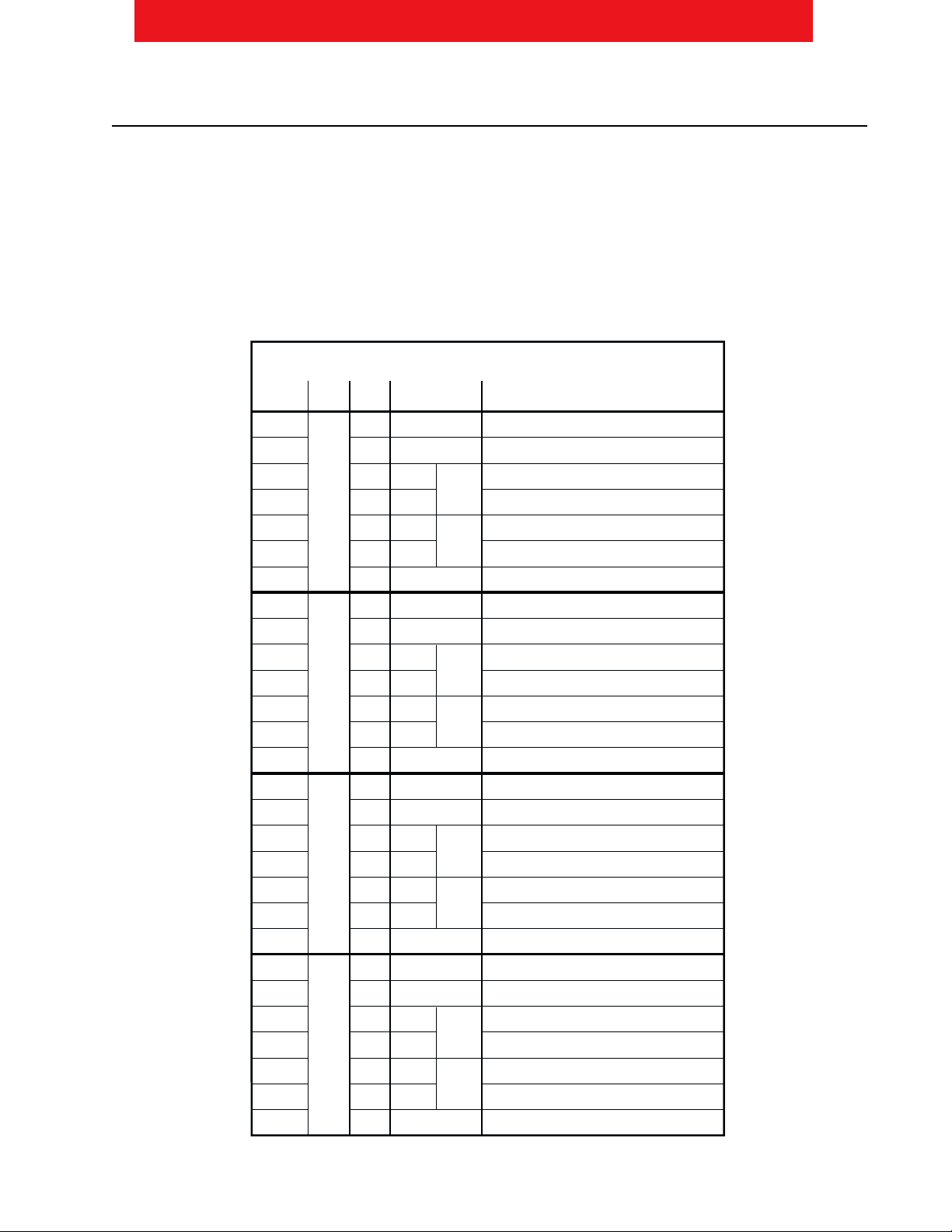
Load Cell Terminal Block (TB1) Pin Out
TB1 Pin
Pin No. Label Function Description
1 1 + EXC Positive Excitation for Channels 1 + 5
2 2 - EXC Negative Excitation for Channels 1 + 5
3 3 + SIG Positive Signal for Channel 1
4 4 - SIG Negative Signal for Channel 1
5 5 + SIG Positive Signal for Channel 5
- SIG Negative Signal for Channel 5
7 7 Shield Shield for Channel 1 + 5
8 1 + EXC Positive Excitation for Channels 2 +
9 2 - EXC Negative Excitation for Channels 2 +
10 3 + SIG Positive Signal for Channel 2
11 4 - SIG Negative Signal for Channel 2
12 5 + SIG Positive Signal for Channel
13 - SIG Negative Signal for Channel
14 7 Shield Shield for Channel 2 +
15 1 + EXC Positive Excitation for Channels 3 + 7
1 2 - EXC Negative Excitation for Channels 3 + 7
17 3 + SIG Positive Signal for Channel 3
18 4 - SIG Negative Signal for Channel 3
19 5 + SIG Positive Signal for Channel 7
20 - SIG Negative Signal for Channel 7
21 7 Shield Shield for Channel 3 + 7
22 1 + EXC Positive Excitation for Channels 4 + 8
23 2 - EXC Negative Excitation for Channels 4 + 8
24 3 + SIG Positive Signal for Channel 4
25 4 - SIG Negative Signal for Channel 4
2 5 + SIG Positive Signal for Channel 8
27 - SIG Negative Signal for Channel 8
28 7 Shield Shield for Channel 4 + 8
CH 8
CH 4
CH 7
CH 3
CH
CH 2
CH 5
CH 1
T
B
1
A
T
B
1
B
T
B
1
C
T
B
1
D
Page 6 MSI-9008 CellScale Multiplexer •User Guide
M E A S U R E M E N T S Y S T E M S I N T E R N A T I O N A L
MSI-9020 DC Connector Pin Diagram
CellScale Connections
The MSI-9008 Multiplexer must be controlled by an MSI-9000 CellScale. A single CellScale can control up to four (4)
multiplexer devices at one time. This is accomplished by the three digital control line outputs from the CellScale and the
two signal inputs per A/D Converter (ADC) on the CellScale (maximum of 2 A/D Converters per CellScale).
As described in the MSI-9000 CellScale User Guide, there are six channels each with eight sub-channels in a CellScale.
The eight sub-channels are accessed by using the MSI-9008 Multiplexer. The CellScale channels are summarized as
follows:
CellScale Channel Summar
Channel Function
1 ADC1, Input 1
2 ADC1, Input 2
3 ADC2, Input 1
4 ADC2, Input 2
5 Slave CellScale Channels
Math Channels
This system provides for five possible ways to connect MSI-9008 Multiplexers (Mux) to a single MSI-9000 CellScale.
These connections are described below.
• Connecting one Mux to CS - maximum of 9 load cell inputs.
• Connecting two Mux to CS with one ADC - maximum of 16 load cell inputs.
• Connecting two Mux to CS with two ADC - maximum of 18 load cell inputs.
• Connecting three Mux to CS (two ADC inputs required) - maximum of 25 load cell inputs.
• Connecting four Mux to CS (two ADC inputs required) - maximum of 32 load cell inputs.
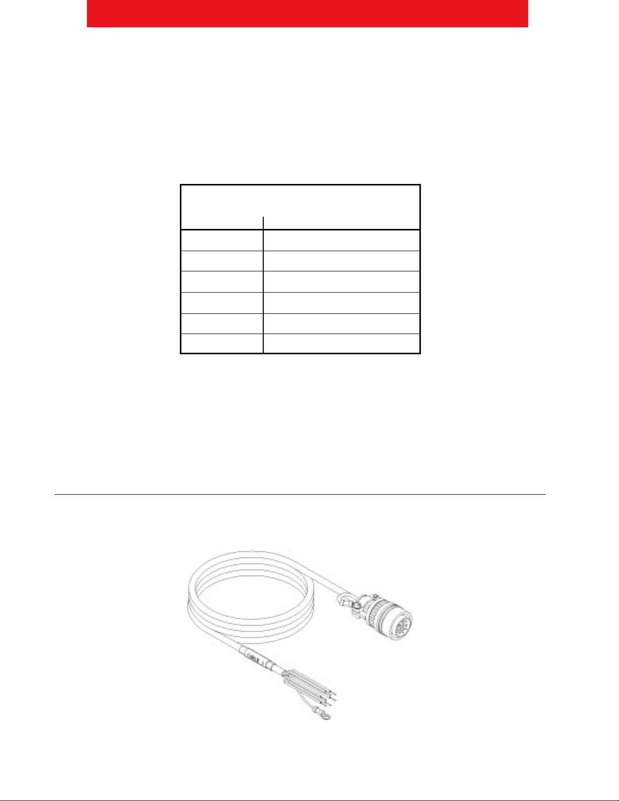
Multiplexer Cable #501802
The Multiplexer requires a shielded 12-conductor cable (MSI part number 501802-00XX) to connect to a master
CellScale Device. The cable assembly is pictured below.
MSI-9008 CellScale Multiplexer •User Guide Page 7
M E A S U R E M E N T S Y S T E M S I N T E R N A T I O N A L
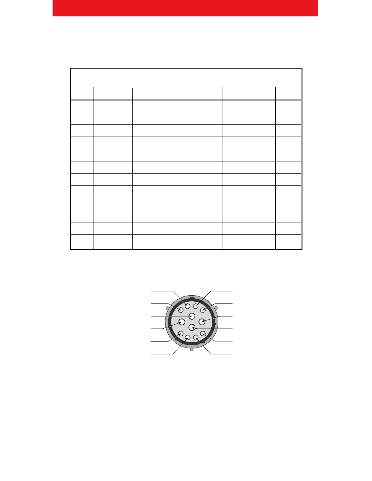
The following table designates the pin out of the CellScale load cell connector, the 501802 cable wire color code, and the
TB2 connector pin out on the 501967 PCA.
CellScale Connector Terminal Block Pinout
TB2 Wire Cable
Pin # Label Description Color Pin #
1 DIG2 Digital Control 2 Gray E
2 DIG1 Digital Control 1 White/Orange D
3 DIG0 Digital Control 0 White/Gray C
4 GND Circuit Ground Orange F
5 - SIG Pass Negative Signal Pass thru White/Black H
+ SIG Pass Positive Signal Pass thru Green/White G
7 - SIG Act Negative Signal Active Output White J
8 + SIG Act Positive Signal Active Output Green K
9 - EXC Negative Excitation Black L
10 - Sense Negative Sense Brown B
11 + Sense Positive Sense Blue A
12 + EXC Positive Excitation Red M
The following diagram shows the typical load cell connector for a CellScale device.
AH
G
B
J
K
M
F
L
C
D
+ Sense (A)
- Sense (B)
- Signal Channel 1 (J)
+ Signal Channel 1 (K)
Mux Crtl Dig0 (C)
Mux Crtl Dig1 (D)
(H) - Signal Ch 2
(G) + Signal Ch 2
(H) + Excitation
(L) - Excitation
(F) Dig Gnd
(E) Mux Crtl Dig 2
Page 8 MSI-9008 CellScale Multiplexer •User Guide
M E A S U R E M E N T S Y S T E M S I N T E R N A T I O N A L
Multiplexer Cable #502305
To connect a secondary Multiplexer to a primary Multiplexer requires the secondary cable assembly, MSI part number
502305. This cable connects from TB2 on the secondary Multiplexer to TB2 on the primary Multiplexer. The following
table shows the connections.
Secondar Multiplexer Cable 502305 Connections
Secondary Secondary Primary Primary
Mux Mux Wire Mux Mux
TB2 Pin # Label Color TB2 Pin # Label
1 DIG2 Gray 1 DIG2
2 DIG1 White/Orange 2 DIG1
3 DIG0 White/Gray 3 DIG0
4 GND Orange 4 GND
7 - SIG Act White/Black 5 - SIG Pass
8 + SIG Act Green/White + SIG Pass
9 - EXC Black 9 - EXC
10 - Sense Brown 10 - Sense
11 + Sense Blue 11 + Sense
12 + EXC Red 12 + EXC
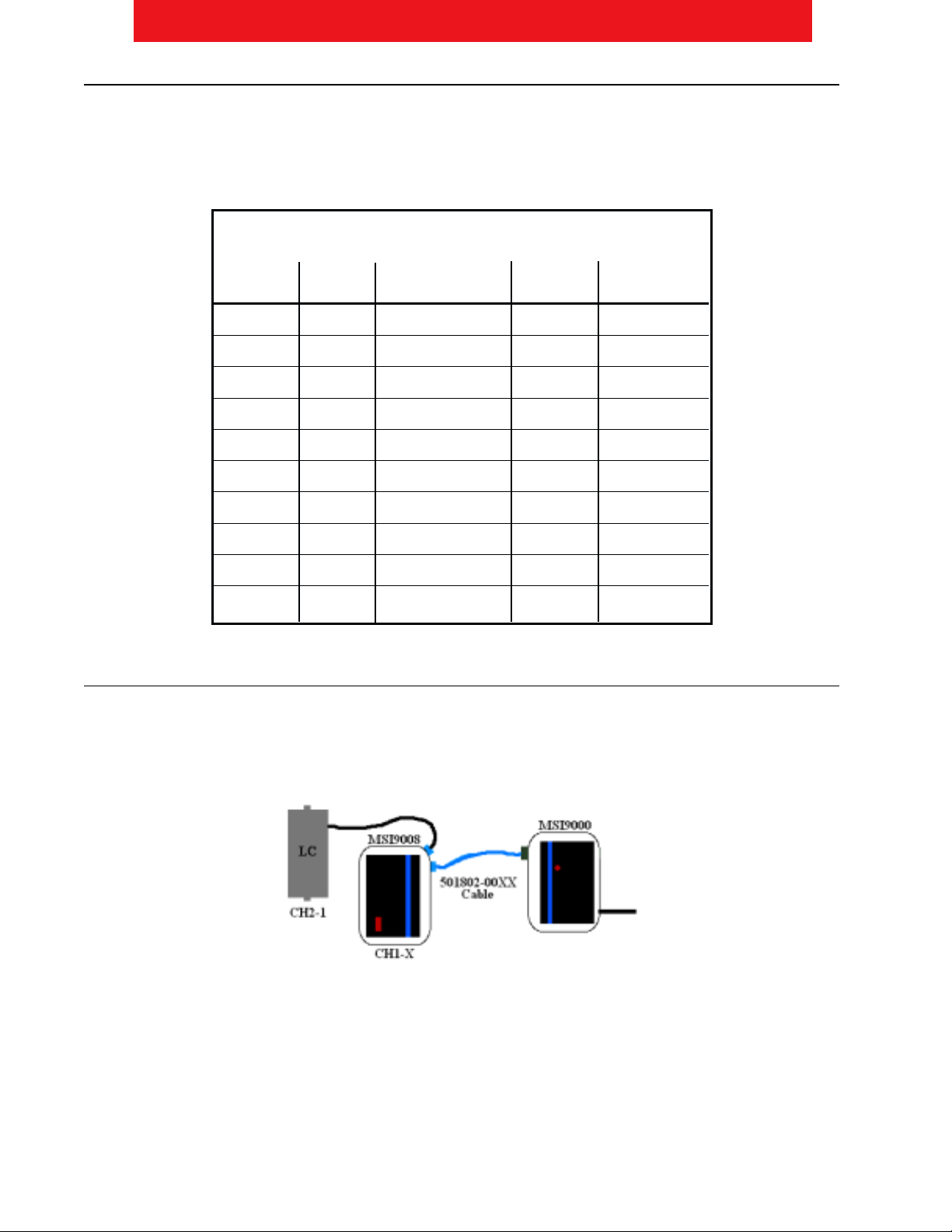
Connecting One Multiplexer to CellScale
When connecting a single Multiplexer to a CellScale, the CellScale can control a maximum of nine load cells. This is
accomplished by connecting a Multiplexer with up to eight load cells to one CellScale input and a single load cell to the
second input. The following diagram illustrates this.
This connection requires the use of the pass thru signal to be used for the ninth load cell. This ninth load cell will be
added to the CellScale scan list as channel 2-1. For information about how to setup the CellScale scan list for this
configuration, see the ”Software Setup section.
MSI-9008 CellScale Multiplexer •User Guide Page 9
M E A S U R E M E N T S Y S T E M S I N T E R N A T I O N A L
Connecting Two Multiplexers to CellScale with One A/D
To connect two Multiplexer units to a CellScale with one A/D input requires the digital control lines and excitation lines
be shared among the two MSI-9008 Multiplexers. The active signal output from the primary Multiplexer will be input to
the CellScale signal input one. The active signal output from the secondary Multiplexer will be input to the pass thru
connection on the primary Multiplexer; which intern, is connected to the CellScale channel two signal input.
For information about how to setup the CellScale scan list for this configuration, see the ”Software Setup” section.
Connecting Two Multiplexers to CellScale with Two A/D’s
When connecting two Multiplexers to a CellScale, the CellScale can control a maximum of eighteen load cells. This is
accomplished by connecting a Multiplexer with up to eight load cells to each CellScale input and a single load cell to the
second inputs on each ADC. The following diagram illustrates this.
This connection requires the use of the pass thru signal to be used for the channel two and channel four load cells. For
information about how to setup the CellScale scan list for this configuration, see the “ Software Setup” section.
Connecting Three Multiplexers to CellScale (Two A/D inputs required)
In order to connect three multiplexer units to a single CellScale, the CellScale will have to be equipped with the optional
second A/D input. This connection will allow two Multiplexers to connect to one A/D input and the third Multiplexer to
connect to the second A/D input on the CellScale. An additional load cell may be input directly to the CellScale on the
second channel input of the second ADC. The following diagram illustrates this.
The last load cell will be added to the CellScale scan list as channel four. For information about how to setup the
CellScale scan list for this configuration, see the “ Software Setup” section.
Page 10 MSI-9008 CellScale Multiplexer •User Guide
M E A S U R E M E N T S Y S T E M S I N T E R N A T I O N A L
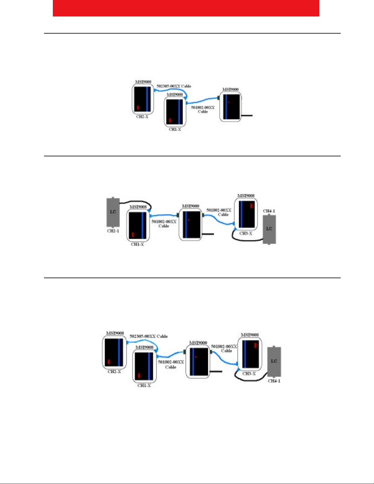
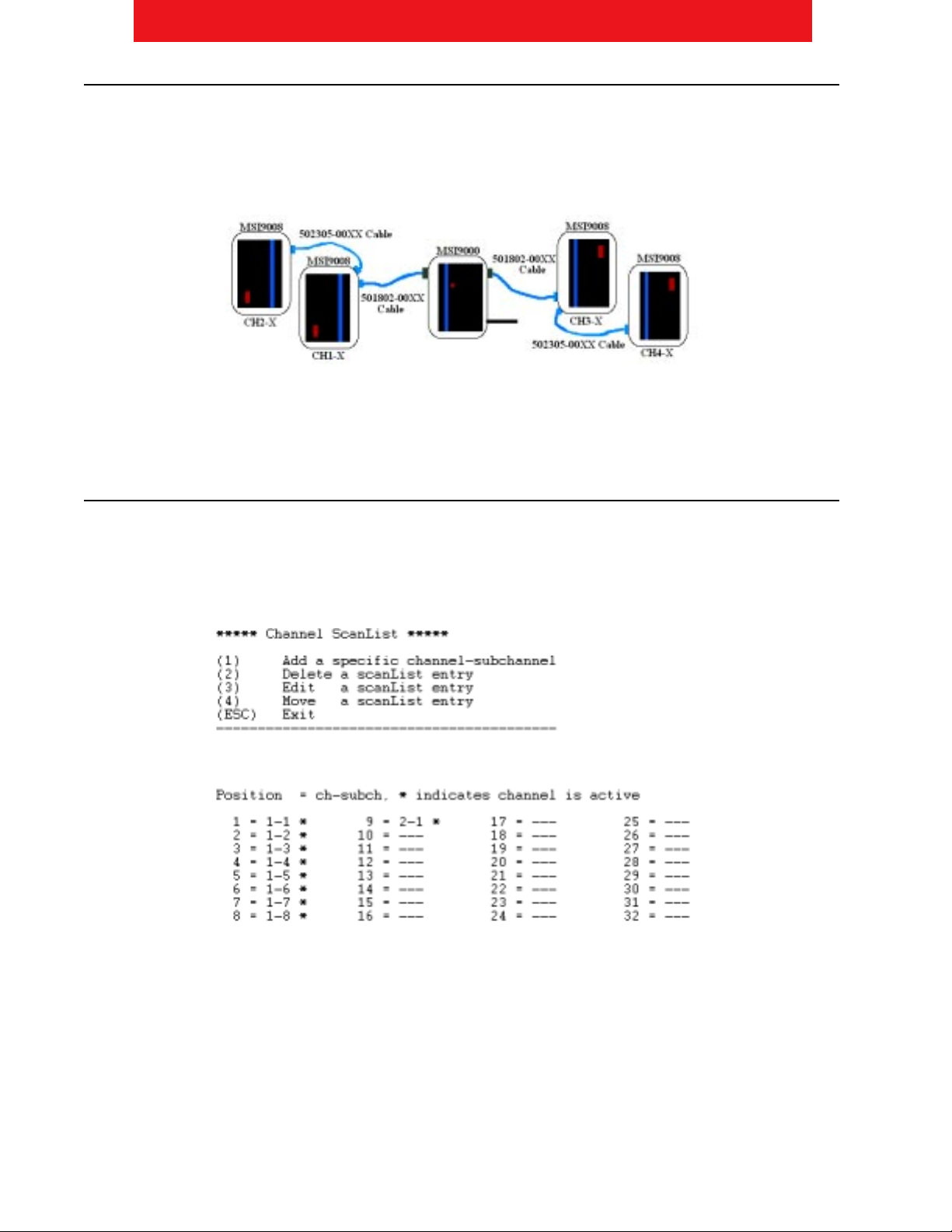
Connecting Four Multiplexers to CellScale (Two A/D inputs required)
A single CellScale can control, at most, four Multiplexers. The primary Multiplexers will connect directly to the two load
cell inputs on the CellScale, typically as channel 1 and channel 3. The secondary Multiplexers will connect to the pass
thru of the primary Multiplexers, then to the inputs on the CellScale, typically as channel 2 and 4. The following diagram
illustrates this.
For information about how to setup the CellScale scan list for this configuration, see the “ Software Setup” section.
Software Setup
For details of operating the CellScale software, please reference the CellScale owner’s manual in addition to the content
provided here.
Connecting One Multiplexer To CellScale
When connecting a single Multiplexer to a CellScale, the load cell’s attached to the Multiplexer will be entered in the
CellScale scan list as 1-X, where X corresponds to the labeled input on the Multiplexer. The ninth load cell input (if used)
will be entered into the CellScale scan list as channel 2-1. An example scan list is shown below.
For details about connecting the hardware for this configuration, see the “CellScale Connections” section.
Table of contents
Popular Multiplexer manuals by other brands


ADTRAN
ADTRAN Frameport 768 Specifications

Elo TouchSystems
Elo TouchSystems E247 Operation manual

Paradyne
Paradyne Hotwire 8786 installation instructions

RFL Electronics
RFL Electronics 9508D UCC instruction manual

Miranda
Miranda AMX-101i Guide to installation and operation

ShipModul
ShipModul MiniPlex-AIX NMEA-0183 manual


