MSM MTU AIS-C User manual

mesemar.com
Rv01
USER MANUAL
MTU AIS-C

mesemar.com
Rv01
USER MANUAL
REF: MTUAIS-C-ENG
Rv. 01
Rv.
DATE
REVISION
01
06-08-2020
General Review 2020
02
19-11-2020
Drawings

mesemar.com
Rv01
INDEX
MTU AIS-C
1. INTRODUCTION TO AIS...................................................................................2
1.1. PURPOSE OF AIS................................................................................................. 3
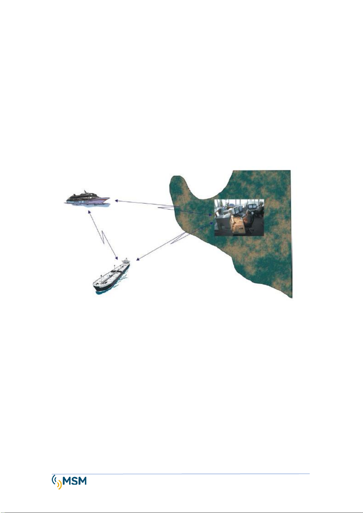
1.2. SHIP TO EARTH INFORMATION.......................................................................... 4
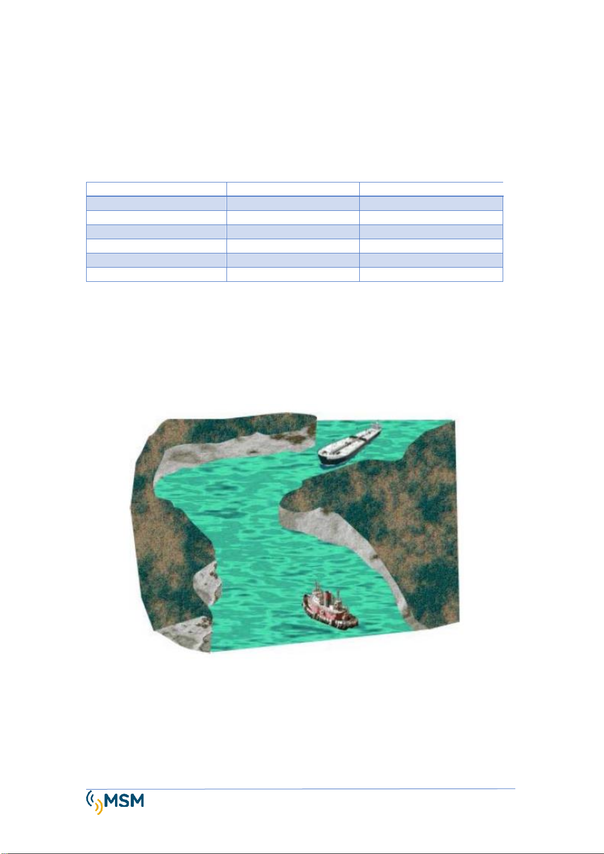
1.3. VESSEL TRAFFIC SYSTEMS VTS ........................................................................... 5
1.4. HOW DOES AIS WORK?...................................................................................... 5
1.5. FREQUENCIES AND AIS TRANSMISSION. ........................................................... 5
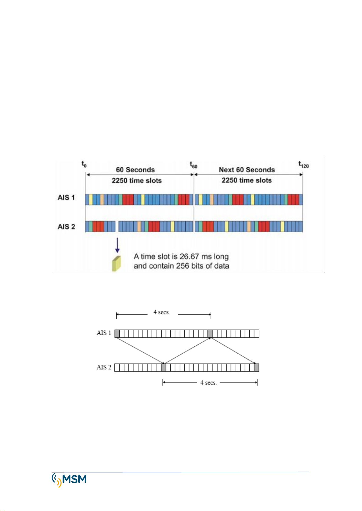
1.6. THE SOTDMA PROTOCOL................................................................................... 6
1.7. DATA REFRESH SPEED........................................................................................ 7
2. DESCRIPTION OF MTU-AIS-C...........................................................................8
2.1. AIS AtoN TYPE 1. ................................................................................................ 8
2.2. AIS AtoN TYPE 3 ................................................................................................. 8
3. GENERAL FEATURES .......................................................................................9
3.1. MAIN FEATURES OF THE SYSTEM .................................................................... 11
3.2. CONNECTOR FEATURES ................................................................................... 11
4. INSTALLATION.............................................................................................. 12
4.1. POWER AND INTERFACE CONNECTOR. "W TYPE"........................................... 13
4.2. SENSOR INTERFACE CONNECTOR. "X TYPE".................................................... 14
4.3. SENSOR INTERFACE CONNECTOR. "Y TYPE".................................................... 15
4.4. VHF ANTENNA CONNECTOR............................................................................ 16
4.5. GPS ANTENNA CONNECTOR ............................................................................ 16
4.6. POWER CONNECTOR (W) ................................................................................ 16
4.7. INSTALLING THE VHF RADIO ANTENNA........................................................... 17
4.8. INSTALLING AND CONNECTING A GPS ANTENNA ........................................... 17
5. CONFIGURATION USING PROATON SOFTWARE ............................................ 18
5.1. PROAtoN INSTALLATION.................................................................................. 18
5.2. CONFIGURATION SCREEN................................................................................ 19
5.3. MTU-AIS CONFIGURATION .............................................................................. 21
5.4. OFFLINE CONFIGURATION............................................................................... 29
6. MTU-AIS REPEATER FUNCTION..................................................................... 30
7. MTU-AIS DIAGNOSTIC .................................................................................. 31

mesemar.com
Rv01
7.1. GPS TAB............................................................................................................ 31
7.2. TAB SERIAL DATA. ............................................................................................ 31
7.3. DIAGNOSTIC TAB.............................................................................................. 32
8. STAND-BY MODE.......................................................................................... 34
9. CONFIGURING THE PCA SENSOR MODULE .................................................... 34
9.1. MESSAGE DATA MAPPING #6.......................................................................... 39
9.2. COMPATIBLE EXTERNAL DEVICES.................................................................... 40
10. ACCESSORIES. .............................................................................................. 41
10.1 OPTIONAL (SENSORS) ...................................................................................... 41
11 DRAWING & DIMENSIONS............................................................................ 42

USER MANUAL MTU AIS-C Page 2
Rv01
1. INTRODUCTION TO AIS
The AIS Automatic Identification System was conceived as an element of radio communication
to improve the safety and efficiency of Maritime Navigation
The AIS system is designed to operate in one of the following modes:
- Collision prevention.
- Identification of ships and goods by the coastal authorities.
- Port traffic management tool.
WHAT IS AIS?
It is basically a digital radio system that uses
various instruments and sensors as inputs.
These entries are processed and transmitted in
accordance with international standards that
have been accepted for the exchange of
information.
This process is carried out without intervention
from the crew.
The AIS is also capable of transmitting small
messages to other ships or base stations by the
crew as a free text for information exchange.

USER MANUAL MTU AIS-C Page 3
Rv01
1.1. PURPOSE OF AIS.
The AIS system allows all ships that equip it to exchange information about navigation. This data
can help other ships plan their routes and increase safety. Allows you to include AtoN navigation
aids by equipping them with AIS equipment as part of the navigation environment.
The data that can be exchanged is divided into three categories:
STATIC
DYNAMIC
TRIP
IMO number
Coordenadas UTC
Draft
Number
Course
Dangerous goods
Sleeve and longing
Speed
ETA / Destination
Type of boat
Navigation status
Route
GPS antenna position
Rudder
Turning speed
Static information is programmed manually, the dynamics are obtained from the ship's sensors
and the travel is regularly updated by the crew during the trip.
As the AIS transponder is a VHF data communication, it allows to identify other ships behind
obstacles that with the use of radar would not be seen, and thus be prevented before a visual
contact.

USER MANUAL MTU AIS-C Page 4
Rv01
1.2.SHIP TO EARTH INFORMATION.
In coastal waters, local authorities can set up an AIS network to monitor boat traffic through
their waters.
These Base Stations can simply monitor AIS information in VHF and can also send messages to
AIS transponders installed on ships. The data they can obtain includes name and license plate of
the ship, destination, ETA and cargo information. In addition, these base stations emit messages
with weather and tide information.
AIS systems record and record all received information so that it can subsequently be
reproduced in the event of an accident. The AIS is used in rescue operations, allowing to
coordinate and monitor the movements of the ship.

USER MANUAL MTU AIS-C Page 5
Rv01
1.3.VESSEL TRAFFIC SYSTEMS VTS
AIS information integrates with VTS systems and provides a powerful tool to monitor ship
movements in the port areas. The combination of the use of Radar and AIS on a single VTS
display provides very reliable and accurate information, especially in areas outside radar range.
1.4.HOW DOES AIS WORK?
The AIS system can work in three ways:
- Standalone or continuous mode.
- Assigned mode.
- Interrogation mode.
Standalone or continuous mode.
In this mode the AIS transponder transmits your position information freely until it enters the
buffer of an AIS base station or other ship. At this point they both synchronize their AIS
computers and remain in this state until they communicate with any other AIS drive.
Assigned mode.
In this mode the base station assigns a slot to each AIS transponder within its action area and
defines the refresh rate of the data.
Interrogation Mode
The AIS transponder provides position information and other data when questioned by another
ship or base station.
BASIC COMPONENTS.
The basic components that allow the operation of an AIS transponder are:
2 TDMA receivers
1 receptor FDMA.
1 trasmisor TDMA
1 microprocessor.
1 interface with navigation sensors.
1.5.FREQUENCIES AND AIS TRANSMISSION.
The internationally defined AIS frequencies for use in maritime traffic are:
AIS 1 = 161,975 MHz
AIS 2 = 162,025 MHz.
AIS transponders can work at different frequencies, within the same band. The working
frequencies are defined regionally by the competent national authority.
The AIS can be controlled by DSC (digital selective calling) to move to another frequency with a
bandwidth of 25 KHz.

USER MANUAL MTU AIS-C Page 6
Rv01
1.6.THE SOTDMA PROTOCOL.
The AIS system employs for communications a self-organized time-division protocol that has
been inherited from air navigation.
This protocol allows a transponder to quickly integrate into a data network via radio along with
other equipment without interference or data collisions.
The protocol also allows communications between terminals in the same way as it is done on
GSM telephony networks.
The protocol has a 60s window with 2250 slots and includes 256 bits in each slot.
Each AIS unit has 2 receivers and a transmitter that can transmit in both AIS1 and AIS2 bands as
shown in the figure.
This transmission format allows data refresh up to a maximum speed of 2 seconds, spreading
half the stream load on each channel. This allows simultaneous ship-ship and ship-to-land
communications.
The coverage and distance of communications will depend on the transmission powers (usually
12W on ships and between 2 and 12 W in AtoN); and antennas and their location above MSL sea
level.

USER MANUAL MTU AIS-C Page 7
Rv01
1.7.DATA REFRESH SPEED.
Navigation information is updated to other ships and base stations according to navigation
needs so that no further information is generated than necessary in AIS channels.
The recommended refresh rate for the data is:
TRANSPONDER CLASS A (SINGLE SHIPS)
Navigational conditions
Shipping interval
Boat anchored or moving at less than 3 knots
3 minutes
Boat between 3 –14 knots
10 seconds
Boat between 3 –14 knots and changing course
3.5 seconds
Boat between 14 –23 knots
6 seconds
Boat between 14 - 23 knots changing course
2 seconds
Boat at more than 23 knots
2 seconds
Boat at more than 23 knots changing course
2 seconds
OTHER AIS TEAMS.
Navigational conditions
Shipping interval
Class B at less than 2 knots
3 minutes
Class B between 2 –14 knots
30 seconds
Class B between 14 - 23 knots
15 seconds
Class B at more than 23 knots
5 seconds
AIS in AIS AtoN Beacons Message 21
3 minutes
AIS Base Station
10 seconds

USER MANUAL MTU AIS-C Page 8
Rv01
2. DESCRIPTION OF MTU-AIS-C
The MTU-AIS-C transponder is an AIS-AtoN in an IP 67 watertight box, which provides automatic
information about the GPS position of the maritime signal; facilitating the location and
identification of buoys, beacons and headlights on the nautical chart of an AIS base station on
the ground.
This universal MTU device can send status signals and alarms from any type of beacon, rotating
or flashing ones, without the need for additional sensors.
Additionally, it can transmit meteorological and oceanographic data, such as current, wave
height, tides, and wind direction and intensity; all this with minimal energy consumption.
The MTU AIS Transponder meets IMO, IEC, ITU and IALA requirements.
2.1. AIS AtoN TYPE 1.
Type 1 transponders are transmitter-only devices and do not have a radio receiver. They can
work only using Fixed Access Time Division Multiple Access (FATDMA) mode. This working mode
requires a fixed slot for transmission.
2.2. AIS AtoN TYPE 3
Type 3 transponders are transmitter and receiver devices. They can work using FATDMA (Fixed
Access Time Division Multiple Access) mode or RATDMA (Random Access Time Division Multiple
Access) mode.

USER MANUAL MTU AIS-C Page 9
Rv01
3. GENERAL FEATURES
Message 21 content
MMSI Number / Navigation Aid Name.
Position WGS84.
GPS time and date.
Type of navigation aid.
AtoN Indicator: Real, Synthetic, Virtual.
Out-of-position alarm.
Racon fault alarm.
Beacon fault alarm.
Beacon status in Day-Night mode.
Message content 6 GLA (NMEA Interface 0183)
MMSI Number / Navigation Aid Name.
Battery voltage (V).
Beacon current (A).
Beacon status in Day-Night mode.
Beacon fault alarm.
Racon fault alarm.
Out-of-position alarm.
Low battery voltage alarm.
Flasher failure alarm.
5 Optocoupled digital inputs.
Message content 8
MMSI Number / Navigation Aid Name.
Position WGS84.
GPS time and date.
Air/wind temperature: direction and speed, medium and peak.
Atmospheric pressure: mean and trend.
Tide level.
Water temperature.
Power
Power range:
10 a 32 V c.c.
Typical consumption (*):
Type 1: 0.06 Ah/day.
Type 3: 0.5 Ah/day.
(*) Emission every 3 min, at 12.5W.
Features Radio module MTU AIS RF
Frequency range:
156,025 a 162,025 MHz
Number of receivers:
2
AIS Frequency 1:
161.975 MHz 25 kHz
AIS Frequency 2:
162.025 MHz 25kHz.
Receiver Sensitivity:
<-107 dBm to 20% PER (Type 3).
Modulation Mode
25KHz GMSK
Auto diagnosis:
Emission power test, ROE measurement
and supply voltage

USER MANUAL MTU AIS-C Page 10
Rv01
Transmission
Possible messages:
6, 7, 8, 12, 13, 14, 20, 21, 25
Typical transmission:
Every 3 min. Programmable.
Channel bandwidth
25KHz
Transmission power:
1, 2, 5, 12.5W (adjustable).
Modulation Mode
GMSK 25KHz
Control:
Type 1: FATDMA.
Type 3: FATDMA, RATDMA.
GPS
Integrated Receiver:
50 channels, IEC 61108-1.
Antenna:
Activates 35 dB, external marine type.
Versions
MTU AIS Type 1:
Only Emitter.
MTU AIS Type 3:
Transmitter and receiver.
Mechanical and environmental characteristics
Dimensions:
180 x 150 x 90 mm.
Weight:
1.6 kg.
Temperature range:
-25º to 55ºC.
Degree of sealing:
IP 67.
MTU AIS interfaces
E/S Digital:
5 Optocoupled inputs.
2 Relay outputs.
4 Configurable non-isolated inputs/outputs.
Analog Inputs:
2 Insulated inputs 0-36V.
3 Non-insulated inputs 0-32V.
1 Current sensor 0.1 to 10A. (ISENSE)
Ports:
RS-422 bidirectional 38.400 baud NMEA 0183.
RS-422 input 38.400 baud NMEA 0183.
Bidirectional 38.400 baud. NMEA 0183.
Input 38.400 baud NMEA 0183.
2 Configurable RS-232 ports.
USB port for configuration.
SDI12 bus
Standards
IEC AIS Aids to Navigation.
IALA A-126. Edition 1.4.
IEC 62320-2 Edition 1.
IEC 61162-1/2. Edition 2.0.
IEC 60945. Edition 4.
ITU-R M. 1371-4
IEC 61108-1.
Options
Weather station.
Tidal sensor (ground).
Glonass.
Other parameters available.

USER MANUAL MTU AIS-C Page 11
Rv01
3.1. MAIN FEATURES OF THE SYSTEM
-Aid to Navigation (AtoN) identification data emission using Message 21, as well as basic
operating status data.
-Capable of transmitting meteorological and oceanographic data through message 8.
-Ideal for monitoring and remote control of beacons, providing alarms and statuses
through Message 6.
-Manufactured according to IEC AIS Aids to Navigation standards, IEC 62320-2, IEC 60945,
IEC 61108-1, IEC 61162-1/2, ITU-R M.1371-4, IALA A-126.
-Available in two versions:
oMTU AIS-1: Type 1, transmitter only.
oMTU AIS-3: Type 3, transmitter-receiver.
-Generating capacity of 10 virtual and synthetic Aids to Navigation (AtoN) as well as
repeater function.
-Configuration using PROAtoN software under Windows environment and commands via
radio VDL.
-Broken chain position alarm generator.
-Monitoring and Remote-Control Center Software (NETCOM) via AIS, GSM, UHF Radio,
Iridium etc.
3.2. CONNECTOR FEATURES
The connectors used in the MTUAIS are from the well-known brand SOURIAU with a degree of
sealing IP67.
REF.
MTU-AIS CONNECTORS
W
Power supply and basic Transceiver interface.
Souriau UTS6JC14E19SW.
USB
USB for PC setup
Souriau UTS6JC8E4S.
X
Sensor board connections A
Souriau UTS6JC14E19SX.
Y
Sensor board connections B
Souriau UTS6JC14E19SY.
VHF
VHF radio antenna
N Female
GPS
Antenna GPS reception
TNC Female

USER MANUAL MTU AIS-C Page 12
Rv01
4. INSTALLATION
The MTU-AIS-C is designed to be easy to install and configure.
Basic installation requires the connection of a VHF antenna and an optional GPS receiver
antenna as the internal GPS antenna can be used.
The complete configuration with all possible options is shown in the following image:

USER MANUAL MTU AIS-C Page 13
Rv01
4.1. POWER AND INTERFACE CONNECTOR. "W TYPE"
This connector includes both power and communication in a single connector, called a "W"
connector. Provides power to the transponder and RS232 connection. The connector is of the
Soriau brand with reference UTS6JC14E19SW. The pins included in the W connector are listed
below:
PIN
ID
Signal Name
Description
A
VIN-
Negative power connection 0V
B
USER_PWR
Output to 3.3 V DC for interfaces. The maximum current is 200
mA
C
VIN
Positive power connection (10 to 32 V DC)
D
NMEA_0183_TX1-
Port 1 NMEA 0183. TX signal -
E
NMEA_0183_TX1+
Port 1 NMEA 0183. TX + signal
F
NMEA_0183_RX1+
Port 1 NMEA 0183. RX+ signal
G
NMEA_0183_RX1-
Port 1 NMEA 0183. RX signal -
H
NMEA_0183_RX2-
PORT 2 NMEA 0183. RX signal -
J
NMEA_0183_RX2+
PORT 2 NMEA 0183. RX+ signal
K
USER_IO_0
User IO signal 0 (light on/off)
L
USER_IO_1
User IO signal 1 (light status)
M
USER_IO_2
User IO signal 2 (Racon status)
N
GND
Earth for signals
P
RELAY_DR_1
Relay Drive Output 1 *
R
RELAY_DR_2
Relay Drive Output 2 *
S
GND
Earth for signals
T
USER_IO_3
User IO signal 3
U
USER_IO_4
User IO signal 4
V
USER_WKUP
WAKEUP External Input **
* Only available when the configuration includes a sensor interface, otherwise these pins do
not connect
** Use only at your provider's instructions.

USER MANUAL MTU AIS-C Page 14
Rv01
4.2. SENSOR INTERFACE CONNECTOR. "X TYPE"
This connector includes external sensor connections in the same connector, called an "X"
connector.
The connector is of the brand Soriau with reference UTS6JC14E19SX. The pins included in the X
connector are listed below:
PIN
ID
Signal Name
msg6
Description
A
I SENSE-
IBALIZA
Lamp current sensor loop (return) (max. 10A)
B
AN_1+
Analog input 1 non-isolated (+)
C
I SENSE+
IBALIZA
Lamp current sensor loop (input) (max. 10A)
D
S_RS422_TX1_A
Sensor port RS422 signal TX A+
E
S_RS422_TX1_B
Sensor port RS422 signal TX B-
F
S_RS422_RX1_A
Sensor port RS422 signal RX A+
G
S_RS422_RX1_B
Sensor port RS422 signal RX B-
H
S_RS422_TX1
Port 1 RS232 sensor TX signal
J
S_RS422_RX1
Port 1 RS232 sensor RX signal
K
ISO_DI1+
BIT-0
Digital input 1 isolated (+)
L
ISO_DI1-
free
Digital input 1 isolated (-)
M
ISO_DI2+
BIT-1
Digital input 2 isolated (+)
N
ISO_DI2-
Beacon
alarm
Digital input 2 isolated (-)
P
AN_1-
Analog input 1 non-isolated (-)
R
S_DIG_IO_1
Digital input/output 1 not isolated
S
S_RS422_GND
RS422 mass sensor port
T
GND
Signal mass
U
S_DIG_IO_3
Digital input/output 3 not isolated
V
S_DIG_IO_2
Digital input/output 2 not isolated

USER MANUAL MTU AIS-C Page 15
Rv01
4.3. SENSOR INTERFACE CONNECTOR. "Y TYPE"
This connector includes external sensor connections in the same connector, called a "Y"
connector.
The connector is of the Soriau brand with reference UTS6JC14E19SY. The pins included in the Y
connector are listed below:
PIN ID
Signal Name
msg6
Description
A
S_RS232_TX2
Puerto 2 Tx Sensor interface
B
S_RS232_RX2
Puerto 2 Rx Sensor interface
C
S_DIG_IO_4
Digital IO 4 not isolated
D
EXT_ WAKEUP
External Wake Up
E
SDI_DATA
BUS SDI Data signal-
F
ISO_DI_3+
BIT-2
Digital input 3 isolated (+)
G
ISO_DI_3-
Racon alarm NC
Digital input 3 isolated (-)
H
ISO_DI_4+
BIT-3
Digital input 4 isolated (+)
J
ISO_DI_4-
free
Digital input 4 isolated (-)
K
ISO_DI_5+
BIT-4
Digital input 5 isolated (+)
L
ISO_DI_5-
free
Digital input 5 isolated (-)
M
ISO_AN_1+
ANALOG 1
Analog input 1 isolated (+)
N
ISO_AN_1-
0-36V
Analog input 1 isolated (-)
P
ISO_AN_2+
ANALOG 2
Analog input 2 isolated (+)
R
ISO_AN_2-
0-36V
Analog input 2 isolated (-)
S
AN_2+
Analog input 2 non-isolated (positive)
T
AN_2-
Analog input 2 non-isolated (negative)
U
AN_3+
Analog input 3 non-isolated (positive)
V
AN_3-
Analog input 3 non-isolated (negative)
* Only available when the configuration includes a sensor interface, otherwise these pins do not
connect
** Use only at your provider's instructions.

USER MANUAL MTU AIS-C Page 16
Rv01
4.4. VHF ANTENNA CONNECTOR.
The VHF antenna connector is a female 'N' type connector.
It is recommended to use a coaxial cable type RG213 or similar with a maximum length of 30m
to minimize power losses.
The connector must be protected against corrosion by vulcanizing tape.
4.5. GPS ANTENNA CONNECTOR
The GPS antenna connector is a female 'TNC' type connector.
4.6. POWER CONNECTOR (W)
The MTU-AIS requires a DC power supply with a rated voltage of 12VDC or 24VDC and can
operate in a voltage range between 10V and 32VDC.
The current peak when output at 12V is 3A.
The total average consumption will depend on the configuration used and the messages
transmitted periodically.
IMPORTANT NOTICE
The GPS antenna must be active type with 3.3V and must be electrically isolated from the VHF radio
connector otherwise it may cause damage to the AIS.

USER MANUAL MTU AIS-C Page 17
Rv01
4.7. INSTALLING THE VHF RADIO ANTENNA
The correct installation of the VHF antenna is essential for the correct performance
and reliability of the AIS Transponder.
The VHF radio antenna must have the following minimum specifications:
•Center frequency 162MHz
•VSWR < 2.0
•Impedance 50 Ohms
•Minimum power 12.5 Watts
•Gain 1dBi to 6dBi
4.8. INSTALLING AND CONNECTING A GPS ANTENNA
If the installation requires the use of an active GPS antenna, an antenna with the following
minimum characteristics must be used:
•1575.42MHz center frequency for GPS.
•Active gain antenna at least 20 dB
•Power supply 3.3V
•Impedance 50 Ohms
IMPORTANT: The GPS antenna and its coaxial cable must be isolated from the support
structure and VHF radio connection
Table of contents
Popular Marine Radio manuals by other brands

Marine Audio
Marine Audio MA300BK Installation and operation manual

Simons Voss Technologies
Simons Voss Technologies TRA user manual

Garmin
Garmin 190-01098-02 installation instructions

Cobra Marine
Cobra Marine MR HH350 W FLT owner's manual

NorthStar
NorthStar EXPLORER 721 Dimensions

Matsutec
Matsutec HP-528A user manual

Uniden
Uniden UM415 owner's manual

NAUTICAST
NAUTICAST B2 product manual

Garmin
Garmin GTX 330 Mode S Pilot's operating handbook and faa approved airplane flight manual

Garmin
Garmin GTX 3X5 Series installation manual

West Marine
West Marine VHF585 16230534 owner's manual

Icom
Icom MarineComander MXS-5000 instruction manual