Icom MarineComander MXS-5000 User manual

INSTRUCTION MANUAL
MARINECOMMANDER SYSTEM
MXS-5000

i
FOREWORD
Thank you for purchasing Icom’s MXS-5000 Icom
MarineCommander™ system.
IMPORTANT
READ THIS INSTRUCTION MANUAL CAREFULLY
before attempting to operate the MarineCommand-
er™.
SAVE THIS INSTRUCTION MANUAL. This manual
contains important safety and operating instructions
for the MarineCommander™.
EXPLICIT DEFINITIONS
WORD DEFINITION
RDANGER! Personal death, serious injury or an explo-
sion may occur.
RWARNING! Personal injury, fire hazard or electric
shock may occur.
CAUTION Equipment damage may occur.
NOTE
If disregarded, inconvenience only. No risk
of personal injury, fire or electric shock.
Icom, Icom Inc. and the Icom logo are registered trademarks of
Icom Incorporated (Japan) in Japan, the United States, the United
Kingdom, Germany, France, Spain, Russia and/or other countries.
MarineCommander and MarineCommander logo are trademarks of
Icom Incorporated.
C-MAP is a trademark of Jeppesen.
All other products or brands are registered trademarks or trade-
marks of their respective holders.
This product includes software developed by the University of Cali-
fornia, Berkeley and its contributors.
TABLE OF CONTENTS
FOREWORD ······························································ i
IMPORTANT ······························································· i
EXPLICIT DEFINITIONS············································ i
TABLE OF CONTENTS·············································· i
Section 1 BASIC OPERATION DESCRIPTION····1-1
Section 2 PLOTTER OPERATION························2-1
Section 3 RADAR OPERATION····························3-1
Section 4 SOUNDER OPERATION ······················4-1
Section 5 COMMON SETTING ·····························5-1
© Jeppesen 2011, All rights reserved.
Please inquire the purchase of C-MAP Max Chart and the question
concerning C-MAP Max Chart to Jeppesen.
Customer Support
Italy, Spain, Portugal, France, Luxemburg, Croatia, Slovenia, Turkey,
Netherlands, Belgium, Greece, Cyprus, Israel, Africa, Middle East
Tel: +39 0585 794 800
E-mail: EU-customersuppor[email protected]
UK and Ireland
Tel: +44 1293 842603
E-mail: EU-customersuppor[email protected]
Germany, Austria, Switzerland
Tel: +49 6102 508430
E-mail: EU-customersuppor[email protected]
Poland
Tel: +48 58 760 6111
E-mail: EU-customersuppor[email protected]
Norway, Denmark, Greenland, Iceland
Tel: +47 51 46 47 99
E-mail: EU-customersuppor[email protected]
Finland, Sweden
Tel: +46 31 719 34 55
E-mail: EU-customersuppor[email protected]
Russia
Tel: +7 812 327 9894
E-mail: RU-customersuppor[email protected]
Australasia
Tel: +61 2 98 08 6200
E-mail: apac-customersuppor[email protected]
US A, Canada and South America
Tel: +1 508.477.8010
E-mail: US-customersuppor[email protected]
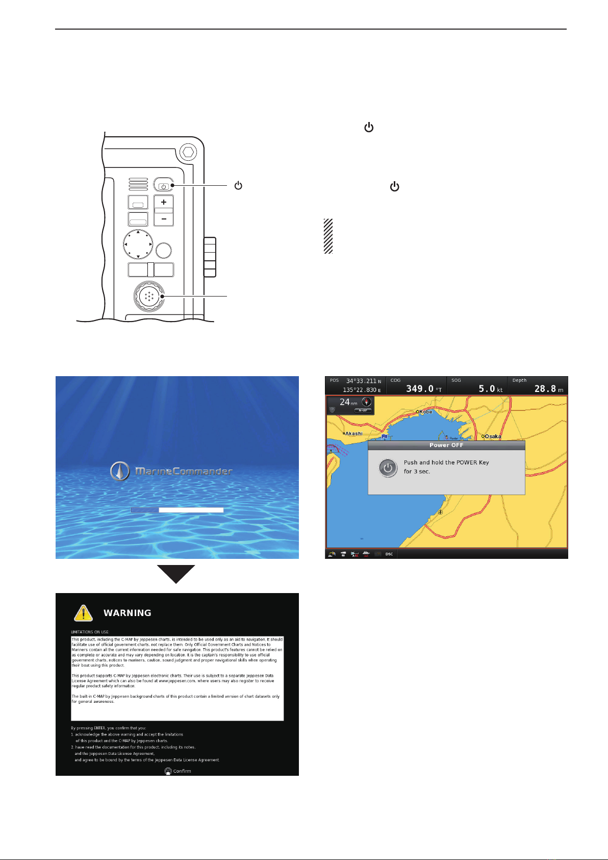
Electronic charts are not legal replacements for
paper charts.
Always carry and consult current official charts
frequently.

1-1
BASIC OPERATION Section 1
■MXD-5000 (Display unit)························································ 1-2
■Turn ON or OFF the power ···················································· 1-6
■Quick Menu 1 operation························································· 1-7
■Screen selection ···································································· 1-8
■Screen arrangement ···························································· 1-12

1
1-2
BASIC OPERATION
q
POWER/DISPLAY BRILLIANCE SWITCH
[ /BRILL]
• While the MarineCommander’s power is OFF
Push to turn ON the MarineCommander’s power.
•While the MarineCommander’s power is ON
➥Push to open Quick Menu 1.
•TheQuickMenu1includestheDisplayBrilliance,
Radar TX setting, Panel Brilliant and Color Palette.
•Pushtwoormoretimestoincreaseordecrease
the display brilliance level.
➥Hold down for 3 seconds to turn OFF the Mari-
neCommander’s power.
wWAYPOINT/MAN OVERBOARD SWITCH
[WPT/MOB]
Push to open the Waypoint screen.➥
•TheWaypointwindowappears.
When a crew member falls overboard, hold down➥
for 3 seconds to mark the man overboard point
on the screen.
•TheMOBreadoutshowsthebearinganddistanceto
the MOB point. (Position data is necessary.)
•Holddown[MOB]for3secondstocancelthefunc-
tion.
eRANGE UP/ DOWN SWITCHES [+]/[–]
Push[+]or[–]tosetasuitablescreenrange.
rFOCUS/DISPLAY LAYOUT SWITCH
[FOCUS/LAYOUT]
Push to change the active screen.➥
•Anorangeborderindicatestheactivescreen.
Hold down for 3 seconds to open the display se-➥
lection screen.
tUP, DOWN, LEFT, RIGHT KEYS [Ù] [Ú] [Ω] [≈]
➥Pusharrow[Ù], [Ú], [Ω]or[≈]tomovethecur-
sor up, down, left or right on the active screen.
Push the dot to move at an angle.
➥IntheMenuscreen,push[Ù]or[Ú]toselectan
item.
➥InQuickMenu1orQuickMenu2,push[Ω]or[≈]
to select an item.
➥InQuickMenu1orQuickMenu2,push[Ù]or
[Ú]toselectanoptionoradjustalevel.
ySUB MENU SWITCH [SUB]
In the Menu screen, push to enter the Sub➥
Menu.
On the Plotter screen, Radar screen or Sounder➥
screen, push to enter the Cursor Menu, depend-
ing on the Cursor position.
uMENU SWITCH [MENU]
Push to select the Menu screen.
P
U
S
H
T
O
E
N
T
E
R
MENU
WPT
FOCUS
LAYOUT
MOB
CLEAR
SUB
BRILL
RANGE
q
w
e
r
t
y
u
■MXD-5000 (Display unit)
DFront panel

1-3
1
BASIC OPERATION
1
2
3
4
5
6
7
8
9
10
11
12
13
14
15
16
17
18
19
20
21
iCLEAR SWITCH [CLEAR]
Push to cancel the current function.
While opening the Menu screen, push to cancel
and return to the upper menu, or cancel the Menu
screen.
oSELECTION DIAL [DIAL]
➥In the Menu screen, rotate to select a menu item
or option.
➥In Quick Menu 1 or Quick Menu 2, rotate to se-
lect an option or adjust a level.
On the Plotter screen
➥Rotate to set the heading position.
!0 ENTER SWITCH
➥In the Menu screen, push to access the selected
menu or function.
➥Push to access Quick Menu 2.
On the Plotter screen
•QuickMenu2includestheCenterShipandPerspec-
tive Angle functions.
On the Radar screen
•QuickMenu2includestheGAIN, SEA, RAIN, Radar
TX menu and Heading line OFF functions.
On the Sounder screen
•Quick Menu 2 includes the GAIN 50kHz, GAIN
200kHz, STC 50kHz and STC 200kHz control func-
tions.
!1 SD CARD PORT
Insert an SD Card which contains C-MAP MAX
chart* by JEPPESEN.
* Chart data is not supplied by Icom.
•An unmount operation should be performed before
removing the SD Card. If you do not unmount the SD
Card, the MarineCommandert m will stop operating.
!2 USB MEMORY PORT
Connect a USB memory stick.
•Anunmountoperationshouldbeperformedbeforere-
moving the USB memory stick. If you do not unmount
the USB memory stick, the MarineCommandert m will
stop operating.
P
U
S
H
T
O
E
N
T
E
R
MENU
WPT
FOCUS
LAYOUT
MOB
CLEAR
SUB
BRILL
RANGE
i
o
!0
!1
!2
DFront panel

1-4
1BASIC OPERATION
q DATA-BAR
Shows various information on palettes 1 to 4.
•Atotalof20optionsareselectable.
The Selectable options are Date/Time, Position, COG/
SOG, COG, SOG, Heading/STW, Heading, STW, Depth/
Temp., Depth, Temp., Trip Log, Waypoint, XTE, ETA/
TTG, ETA, TTG, Cursor, Startus and Wind.
w PALETTE1
Shows various information.
(Default: Position)
Shows the current position data* in latitude/longi-
tude.
*Depending on the presetting, Loran-C Time differences
are displayed instead of the position data.
•When the position data is invalid, the position data is
shown in red for 1 minute. After 1 minute has passed,
“–––” (invalid data) will appear.
e PALETTE2
Shows various information.
(Default: COG)
Shows your vessel’s course over ground.
•“T”showstruenorthbearing,and“M”showsmagnetic
north bearing.
r PALETTE3
Shows various information.
(Default: SOG)
Shows your vessel’s speed over ground.
If no speed data is found, “–––” will appear.
t PALETTE4
Shows various information.
(Default: Depth)
Shows the current depth of the sea bottom, under
the vessel.
When a companion Icom fish finder is not connected
to the main unit, or the sea bottom is not detected,
“–––” (invalid data) will appear.
y CROSS HAIR CURSOR
Appearsandmovesonthescreenwhen[Ù], [Ú],
[Ω] or [≈] is pushed.
ew
q
tr
y
Move the cursor on
the screen, then
push [SUB] to toggle
between minimize or
original.
DDisplay

1-5
1
BASIC OPERATION
1
2
3
4
5
6
7
8
9
10
11
12
13
14
15
16
17
18
19
20
21
u STATUS-BAR
➥Shows the status data.
•Atotalof19optionsareselectable.
The selectable options are Date/Time, Position, COG/
SOG, COG, SOG, Heading/STW, Heading, STW,
Depth/Temp., Depth, Temp., Trip Log, Waypoint, XTE,
ETA/TTG, ETA, TTG, Wind and Cursor.
•When several options are set to be displayed, the
data will be displayed in order.
(Default: Date/Time)
Shows the current time.➥
•“--:--”appearswhennotimedataisreceived.
Shows the current date.➥
•“----/--/--”appearswhennodatedataisreceived.
➥When a menu or dialogue is displayed on the
screen, an operation guide for that is displayed
here, instead of the status data.
i FOCUS BAR
This field shows and selects the icons. When this
bar is selected, the color of the bar changes to or-
ange.
o DSC MESSAGE ICON
Blinks when there is an unread message.
!0 TRANSCEIVER ICON
Appears when a companion Icom transceiver is
connected to the Main unit.
!1 FISH FINDER ICON
Display as an animation when a companion Icom➥
fish finder is connected and operating.
Appears, but not as an animation, when the fish➥
finder is connected but not operating.
An “X” appears on the icon when the fish finder is➥
not connected to the main unit.
!2 AIS UNIT ICON
Appears, but with an “X” below the icon when the
AIS unit is not connected to the Main unit.
The "X" disappears when an AIS unit is connected
to the Main unit and an AIS signal is received.
!3 RADAR ICON
Appears when a companion Icom radar unit is➥
connected and is in the stand-by mode.
Appears and rotates when the radar is operat-➥
ing.
Appears with “SAVE” (but doesn’t rotate) when➥
the radar is in stand-by in the save mode.
Appears with “SAVE” and rotates when the radar➥
is operating in the save mode.
An “X” appears on the icon when the radar is not➥
connected to the main unit.
!4 GPS RECEIVER ICON
Appears when position data is received.
•An“X”appearsontheiconwhenthepositiondataisnot
received, or is invalid.
uoi!1!4 !3 !2 !0
DDisplay

1-6
1BASIC OPERATION
Push[q]toturnONthepower.
•The system will sound an electronic beep, and then
opening screen is displayed.
After you conrm the opening screen, push [EN-w
TER]toentertheoperatingscreen.
Holddown[e]for3secondstoturnOFFthepow-
er.
At the first turning ON the MarineCommandert m or
after performing Factory Reset, Initial Setting screen
(p. 5-33) appears before opening screen is displayed.
MENU
WPT
FOCUS
LAYOUT
MOB
CLEAR
SUB
BRILL
RANGE
[ENTER]
[ ]
Turn ON or OFF the power■
• Opening screen • Power OFF screen

1-7
1
BASIC OPERATION
1
2
3
4
5
6
7
8
9
10
11
12
13
14
15
16
17
18
19
20
21
Quick Menu 1 includes the Display Brilliance, Radar
TX setting, Panel Brilliant and Color Palette.
Push[BRILL]toopenQuickMenu1.q
Push[wt]or[u]toselectthedesiredtab.
Rotate [DIAL] to adjust or select the value or op-e
tion.
rPush[ENTER]tosetandexitQuickMenu1.
•Push[CLEAR]tocancelandexitQuickMenu1.
Push to open Quick Menu 1.q
Rotate [DIAL] to adjust the Display Brilliance be-w
tween 0 and 30 in 1 level steps.
Orpush [BRILL] twoor moretimesto increase or
decrease the display brilliance level.
•Thedisplaybrilliantincludesto5,10,15,20,25,30or
decrease to 0.
Push to open Quick Menu 1.q
Push[wu]oncetoselecttheRadarTXsetting.
•Ifnecessary,push[t]tomovetolefttab.
Rotate[DIAL]toselectthesetting,“TX”or“STBY”e
button.
rPush[ENTER]tosetandexitQuickMenu1.
•Push[CLEAR]tocancelandexitQuickMenu1.
Push to open Quick Menu 1.q
Push[wu]threetimestoselecttheColorPalette.
Rotate[DIAL]toselectthesetting,“Day”or“Night”e
button.
rPush[ENTER]tosetandexitQuickMenu1.
•Push[CLEAR]tocancelandexitQuickMenu1.
Push to open Quick Menu 1.q
Push[wu]twicetoselectthePanelBrilliant.
•Ifnecessary,push[t]tomovetothelefttab.
Rotate[DIAL]toadjustthePanelBrilliantbetween0e
to 8 in 1 level steps.
MENU
WPT
FOCUS
LAYOUT
MOB
CLEAR
SUB
BRILL
RANGE
[DIAL]/
[ENTER]
[CLEAR]
[] or []
[BRILL]
Quick Menu 1 operation■
Display BrillianceD
Radar TX settingD
Panel BrilliantD
Color PaletteD

1-8
1BASIC OPERATION
If you have installed an MXR-5000R/T Radar unit or an
MXF-5000 Fish Finder unit, and you want to change
the operating screen, following procedure is neces-
sary.
Holddown[LAYOUT](FOCUS)for3secondstoen-q
ter the screen selection mode.
Rotate[DIAL]toselectthedesiredoperatingscreen,w
thenpush[ENTER].
•Twosplitscreensorthreesplitscreenscanbeselected
in default setting.
•Push [CLEAR] to cancel and return to the previous
screen before entering the screen selection mode.
The screen layouts can be customized. See page 1-12 for
details.
MENU
WPT
FOCUS
LAYOUT
MOB
CLEAR
SUB
BRILL
RANGE
[DIAL]/
[ENTER]
[CLEAR]
[LAYOUT]
Screen selection■
• Screen selection mode
• 2 Screens selection • 3 Screens selection

1-9
1
BASIC OPERATION
1
2
3
4
5
6
7
8
9
10
11
12
13
14
15
16
17
18
19
20
21
When two or more split screen is selected, and you
want to change the active screen, following procedure
is necessary.
Push[FOCUS]oneormoretimestoselectthede-➥
sired screen.
•Theoutsideframe of theactivescreenchangestoor-
ange.
MENU
WPT
FOCUS
LAYOUT
MOB
CLEAR
SUB
BRILL
RANGE
[FOCUS]
Selecting Active screenD
Push[FOCUS]oneormoretimestoselecttheFo-q
cus Bar.
•ThebackcoloroftheFocusbarchangestoorange.
Rotate[DIAL]toselectthedesireditem,thenpushw
[ENTER].
•Theoutsideframeoftheactiveiconchangestowhite.
Push [CLEAR] to cancel and return to the Focuse
bar.
rPush[FOCUS]toreturntotheactivescreen.
MENU
WPT
FOCUS
LAYOUT
MOB
CLEAR
SUB
BRILL
RANGE
[DIAL]/
[ENTER]
[CLEAR]
[FOCUS]
Entering Focus barD
Active screen
Focus bar is selected

1-10
1BASIC OPERATION
GPS Status screen displays the status of the received
GPS.
Push[ENTER]toentertheGPSStatusscreen.q
Push[CLEAR]toexitthescreenandreturntothew
Focus bar.
Radar TX setting selects the Radar TX mode and
Standby mode.
Rotate [DIAL] to select the second icon from theq
left.
•Theoutsideframeoftheactiveiconchangestowhite.
Push[ENTER]toentertheRadarTXmenu.w
•QuickMenu1appears.
Rotate[DIAL]toselectthe“TX”or“STBY”button.e
rPush[ENTER]tosetandreturntotheFocusbar.
The AIS List displays receiving AIS.
Rotate[DIAL]toselectthethirdiconfromtheleft.q
•Theoutsideframeoftheactiveiconchangestowhite.
Push[ENTER]toentertheAISListmenu.w
Rotate[DIAL]toselecttheship’sName/MMSI.e
rPush[SUB]toentertheSubmenu.
tRotate[DIAL]toselectthe“ViewDetail,”“SendIndi-
vidual” or “Register ID.”
yPush[CLEAR]toexitthescreenandreturntothe
Focus bar.
• GPS Status
• Radar TX setting (Quick Menu 1)
• AIS List
Focus menu operationD

1-11
1
BASIC OPERATION
1
2
3
4
5
6
7
8
9
10
11
12
13
14
15
16
17
18
19
20
21
If the connected transceiver has received a DSC call,
you can check the DSC call log in this screen.
Rotate[DIAL]toselectthersticonfromtheright.q
•Theoutsideframeoftheactiveiconchangestowhite.
Push [ENTER] to enter the Received Call Logw
menu.
Rotate[DIAL]toselectareceivedCall.e
rWhen the selected call included its position data,
push[ENTER]toputthetransmittedstation’sposi-
tion on the map when the Call has been transmit-
ted.
Orpush[SUB]toopentheSubmenu.
•TheSubMenuincludesFilter,SendACK,GoonChart,
Register ID, Erase Message and Erase All Message.
yPush[CLEAR]toexitthescreenandreturntothe
Focus bar.
Sounder Icon shows the transducer is properly con-
nected.
• Sounder Icon
When Icom transceiver is connected and it’s power
ON, transceiver icon can be selected.
Rotate[DIAL]toselectthefthiconfromtheleft.q
•Theoutsideframeoftheactiveiconchangestowhite.
Push[ENTER]toentertheSendDSCmenu.w
Rotate[DIAL]toselectthedesiredcall,“Individuale
Call,” “Group Call,” “All Ships Call,” “Position Re-
quest,” “Position Report” or “Polling Request.”
•Theselectablecallsdiffer,dependingontheconnected
transceiver.
•The display guide shows the operating guidance. The
operations differ, depending on the selected DSC call.
•Ifdesired,push[CLEAR]toexitthescreenandreturnto
the Focus bar.
• Send DSC
• Received Call Log
Push

1-12
1BASIC OPERATION
Holddown[LAYOUT](FOCUS)for3secondstoen-q
ter the screen selection mode.
Rotate[DIAL]toselecttheNewLayout,thenpushw
[ENTER].
•Push [CLEAR] to cancel and return to the previous
screen before entering the screen selection mode.
Rotate[DIAL]toselectdesiredscreentype.e
•Onescreen,twosplitscreen,threesplitscreenorfour
split screen type can be selected.
•Push[CLEAR]toreturntothepreviousscreen.
rRotate[DIAL]toselectthedesiredapplicationtothe
screen,thenpush[ENTER].
•Push[CLEAR]toreturntothepreviousscreen.
tRepeat step runtil all split screens are selected
their application.
MENU
WPT
FOCUS
LAYOUT
MOB
CLEAR
SUB
BRILL
RANGE
[DIAL]/
[ENTER]
[CLEAR]
[LAYOUT]
Screen arrangement■
Make New LayoutD
You can make a desired operating screen, changing
its application, erasing the screen or changing their
order.
NOTE: The maximum number of screen layouts is 26.
Push
Push

1-13
1
BASIC OPERATION
1
2
3
4
5
6
7
8
9
10
11
12
13
14
15
16
17
18
19
20
21
•Oneortwosplitscreenisselected:
Plotter
Radar
Sounder
Video
•Threesplitscreenisselected
A part of 1/2 screen is same as one or two split
screen.
A part of 1/4 screen is same as four split screen.
•Foursplitscreenisselected
Plotter
Radar
Sounder
Video
Nav-Course Monitor
Nav-Depth Graph
Nav-Navigation
Nav-Temperature Graph
Nav-Navigation (Graphic-Detail)
Nav-Navigation (Graphic-Simple)
Nav-Waypoint
Nav-Engine
Nav-Engine (Graphic)
Selectable ApplicationD
Plotter
Radar
Sounder
Video
Nav-Course Monitor
Nav-Depth Graph
Nav-Temperature Graph
Nav-Navigation
Nav-Navigation (Graphic-Detail)
Nav-Navigation (Graphic-Simple)
Nav-Waypoint
Nav-Engine
Nav-Engine (Graphic)

1-14
1BASIC OPERATION
Holddown[LAYOUT](FOCUS)for3secondstoen-q
ter the screen selection mode.
Rotate [DIAL] to select the desired screen to bew
changed,thenpush[SUB].
•Push [CLEAR] to cancel and return to the previous
screen before entering the screen selection mode.
Rotate[DIAL]toselect“Edit,”thenpush[ENTER].e
•Onescreen,twosplitscreen,threesplitscreenorfour
split screen type can be selected.
•Push[CLEAR]toreturntostepw.
rRotate[DIAL]toselectthedesiredapplicationtothe
screen,thenpush[ENTER].
•Push[CLEAR]toreturntothepreviousscreen.
tRepeat step runtil all split screens are selected
their application.
Change LayoutD
Erase a screen layoutD
Move a screen layoutD
Holddown[LAYOUT](FOCUS)for3secondstoen-q
ter the screen selection mode.
Rotate [DIAL] to select the desired screen to bew
erased,thenpush[SUB].
•Push [CLEAR] to cancel and return to the previous
screen before entering the screen selection mode.
Rotate [DIAL] to select “Erase,” then push [EN-e
TER].
•Conrmationscreenappears.
rRotate[DIAL]toselect“Yes,”thenpush[ENTER].
Holddown[LAYOUT](FOCUS)for3secondstoen-q
ter the screen selection mode.
Rotate [DIAL] to select the desired screen to bew
moved,thenpush[SUB].
•Push [CLEAR] to cancel and return to the previous
screen before entering the screen selection mode.
Rotate[DIAL]toselect“Move,”thenpush[ENTER].e
rRotate[DIAL]tomovethescreen,thenpush[EN-
TER].
Screen arrangement (Continued)■
The default layouts cannot
be changed.
The default layouts cannot
be erased.

2-1
PLOTTER OPERATION Section 2
Plotter display‘.......................................................................... 2-2
Basic operation‘........................................................................ 2-3
Menu operation‘........................................................................ 2-4
Center Ship function‘............................................................... 2-4
Vessel Offset function‘.............................................................. 2-5
Plotter Display Mode selection‘................................................ 2-5
Waypoint operation‘.................................................................. 2-6
Route navigation function‘...................................................... 2-10
Track function‘........................................................................ 2-18
Search function‘..................................................................... 2-24
Ruler function‘........................................................................ 2-27
Presentation‘.......................................................................... 2-28
Anti Clutter function‘............................................................... 2-37
Alarm Setup‘........................................................................... 2-38
Chart Setup‘........................................................................... 2-43
Cursor menu operation‘.......................................................... 2-52

2
2-2
PLOTTER OPERATION
Plotter display■
q
w
e
r
q CURSOR POSITION
Shows the pointed position* of the cross hair cur-➥
sor in latitude/longitude, the bearing and distance
of the pointed position relative to the current ves-
sel position.
*Depending on the presetting, Loran-C Time differ-
ences is displayed instead of the position data.
Placing the cursor directly over the center of the➥
object icon shows the object’s position informa-
tion.
w YOUR VESSEL ICON
Indicates the current vessel’s position. The Icon rep-
resents the current position of your vessel.
•Thevesseliconpointstothebow.
•When no heading information is received, the vessel
icon points to the COG (Course Over Ground).
•When both the heading and COG information are re-
ceived, the vessel icon is displayed as “Ô.”
e NAVIGATION SCREEN
Appears only when the Navigation function is ON.
It shows the destination information.
r PLOTTER DISPLAY INFORMATION
Shows the selected plotter display mode, display
scale, radar overlay status and an arrow which indi-
cates the north.
•Theselectedplotterdisplaymodeicon(e.g.“ ”) is
turned ON when it is enabled. (p. 2-5)
•Whenthecrosshaircursorpointstotheplotterdisplay
mode icon, push [SUB] to switch the mode between “N-
UP” (North-up). “C-UP” (Course-up), “AC-UP” (Automat-
ic Course-up), “TM” (True Motion) and “AR” (Automatic
Range).
•Whenthecrosshair cursorpointstotheradaroverlay
icon (“ ”), push [SUB] to turn the Radar Overlay func-
tion ON or OFF. (The Radar Overlay function can be
turned ON only when the radar unit is in the transmit
status.)

2-3
2
PLOTTER OPERATION
1
2
3
4
5
6
7
8
9
10
11
12
13
14
15
16
17
18
19
20
21
Turn the power ON.q
•ThePlotterscreenappears.
•IfascreenotherthanthePlotterappears:
1. Hold down [LAYOUT](FOCUS) for 3 seconds to enter
the screen selection mode.
2. Rotate [DIAL] to select Plotter.
3. Push [ENTER].
Push [+] or [–] one or more times to select the dis-w
play range.
•Thedisplayrangereadoutshowsthemaximumdistance
range of the screen longitudinal direction.
Push [BRILL](e), then adjust the display brilliance,
backlighting of the keys and a color mode of the dis-
play (day/night). (p. 1-7)
rSelect the Plotter Display mode.
➥Push [MENU], then rotate [DIAL] or push [Ù],
[Ú], [Ω] or [≈] until the “Plotter Display Mode”
menu is highlighted.
Push [ENTER], then rotate [DIAL] or push➥[Ù],
[Ú], [Ω] or [≈] to select one of the following
screens:
•North-up(N-UP)
•Course-up(C-UP)
•AutomaticCourse-up(AC-UP)
•TrueMotion(TM)
•AutomaticRange(AR)
Push[ENTER]toexitthemenuscreen.➥
MENU
WPT
FOCUS
LAYOUT
MOB
CLEAR
SUB
BRILL
RANGE
[ENTER]
[CLEAR]
[MENU]
[+] or [–]
(RANGE)
[BRILL]( )
Basic operation■
• Display brilliance adjustment screen
• Display range readout
Mode Description
N-UP The top of the plotter display represents
North.
C-UP The top of the plotter display represents
the direction your course is heading.
AC-UP
The top of the plotter display represents
the direction your course is heading.
When your course is changed to 6 degrees,
the plotter map automatically rotates to set
the direction.
TM
Theplotterdisplayisxed,andyourvessel
icon moves on the map.
When your vessel icon approach to the
edge of the display, the plotter map will au-
tomatically switch.
AR
While in the navigation, in addition to the
“AC-UP” action, the range of the plotter dis-
play is automatically adjusted according to
the distance between your vessel and the
destination.
While in the not navigation, it is same as
the “AC-UP” action.
• Plotter Display Mode Description

2-4
2PLOTTER OPERATION
Center Ship function ■
This function makes your vessel locate to the center of
the display, and enables the Plotter Display Mode.
Using the Quick menu:
Push [ENTER] to open Quick menu, and push [EN-➥
TER] to set your vessel to center of the screen.
Using the Center Ship menu:
(MENU wCenter Ship)
Push [MENU], and push [ENTER] to set your vesselq
to center of the screen.
Push[CLEAR]oneormoretimestoexittheMenuw
screen.
<Center Ship menu>
Menuscreensallowyoutoselectandexecutevarious
system functions, or to change various settings.
The following summarizes the menu operation flow.
Push [MENU].q
•TheMainmenuscreenappears.
•Thecurrentlyselectedmenuishighlighted.
Rotate [DIAL] to select the desired menu, and pushw
[ENTER].
•TheSubmenuscreenappears.
•OntheSubmenuscreen,thecurrentlyselectedmenuis
highlighted.
Rotate [DIAL] to select the desired menu, and pushe
[ENTER].
rRepeat step euntil the menu option screen ap-
pears.
•Toreturntothepreviousscreen,push[CLEAR].
tRotate [DIAL] to set the desired option.
yRepeat steps eand tto set other items.
uPush[CLEAR]oneormoretimestoexittheMenu
screen.
Menu operation■
MENU
WPT
FOCUS
LAYOUT
MOB
CLEAR
SUB
BRILL
RANGE
[DIAL]/
[ENTER]
[CLEAR]
[MENU]
[ÙÚΩ≈]
<Main menu>
<Quick menu>
Table of contents
Other Icom Marine Radio manuals

Icom
Icom IC-M802 Quick start guide

Icom
Icom IC-M25 User manual

Icom
Icom IC-M501 Quick start guide

Icom
Icom MA-500TR User manual

Icom
Icom IC-M802 Installation manual

Icom
Icom MA-500TR User manual

Icom
Icom IC-M802 Instruction Manual

Icom
Icom IC-M80 User manual

Icom
Icom IC-M80 User manual

Icom
Icom MA-510TR User manual
Popular Marine Radio manuals by other brands

Garmin
Garmin GTX 330 / 330ES pilot's guide

Furuno
Furuno FM-3000 Operator's manual

Kenwood
Kenwood TK-190 Service manual

Honeywell
Honeywell ESSER IQ8 Operation and installation instruction

Littfinski Daten Technik
Littfinski Daten Technik COL-10 Assembly instruction

Himunication
Himunication HM360 DSC MAX user manual