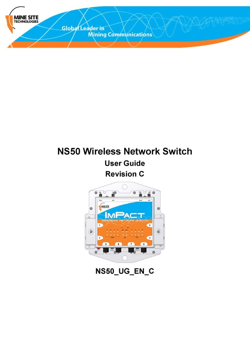
MST Impact NS5001 User manual

©Copyright MST Global 2012
NS50 wireless
network switch
User Manual
Revision C –22 May 2017

NS50 wireless network switch
User Manual
Revision C
© 2012 MST Global
Commercial in Confidence
ii
Revision History
Revision
Change
Date
A
User Manual for NS50 hardware and
firmware February 2012
2.22.16
February 2012
B
Updated for firmware 2.24.2
February 2012
C
Updated power supply recommendations
Textual content-legal
Layout 19.05.17
May 2017

NS50 wireless network switch
User Manual
Revision C
© 2012 MST Global
Commercial in Confidence
iii
Copyright and Disclaimer
Copyright
Published in Sydney by: Mine Site Technologies Pty Ltd (MST Global)
ABN: 93 002 961 953 ACN: 002 961 953
Global Head Office: Level 5, 113 Wicks Road, North Ryde, NSW 2141 Australia
Telephone: +61 (0)2 9491 6500
Copyright © 2012 Mine Site Technologies Pty Ltd (MST Global). All rights reserved. MST Global
reserves the right to make changes to specifications and information in this manual without prior notice.
MST Global accepts no responsibility for any errors or omissions contained in this manual.
This publication is subject copyright. No part of it may in any form or by any means (electronic,
mechanical, microcopying, photocopying, recording or otherwise) be reproduced, stored in a retrieval
system or transmitted without prior written permission of the copyright owner. Enquiries should be
addressed to MST Global.
Warning
Unauthorised reproduction of, alteration of contents, or distribution to third parties, in whole or in part is
an infringement of copyright MST Global will actively pursue any breach of its copyright.
Disclaimer
Information contained in this document has been developed by Mine Site Technologies Pty Ltd (MST
Global). Every care has been taken by the staff of MST to ensure the content of this manual is relevant
and up to date at the time of publication. Content is subject to change without notice. Technical updates
as associated with this manual will be supplied to the customer at MST Global’s earliest convenience.
This manual is published and distributed on the basis that the publisher is not responsible for the results
of any actions taken by users of the information contained in this manual. MST Global does not accept
responsibility for errors or damages resulting from misrepresentation, misinterpretation or deviation from
instructions by any person in regard to the information contained in this manual. The information is
supplied on the condition that the recipient will make their own determination as to the suitability of the
information for their purposes prior to use.

NS50 wireless network switch
User Manual
Revision C
© 2012 MST Global
Commercial in Confidence
iv
Contact Information
Australia
Sydney
Level 5, 113 Wicks Road
North Ryde
Sydney NSW 2113
Tel: +61 (0)2 9491 6500
United States
Denver
13301 W 43rd Drive
Golden, Denver
Colorado 80403
Tel: +1 303 951 0570
Chile
Santiago
Vitacura 2771, 0f 503
Las Condes,
Santiago 7550134
Tel: +56 (2) 2 656 7673
Russia
Moscow
Office 318a
Lesnaya, 43
Moscow 127055
Tel: +7 (499) 978 72 11
South Africa
Centurion
Unit 1, Oxford Office Park
3 Bauhinia St
Gauteng 0046
Tel: +27 (0) 12 345 6100
China
Hangzhou
Building 5
1413 Moganshan Road
Hangzhou 310011
Tel: +86 571 8580 3320 Ext 206

NS50 wireless network switch
User Manual
Revision C
© 2012 MST Global
Commercial in Confidence
v
About This Manual
This manual describes features and functions of the NS50 Wireless Network Switch. It provides
information about hardware, installation, configuration and how to troubleshoot any issues. You will find
it easier to use the manual if you are familiar with networking systems and have an understanding of
electronics in a network environment.
Conventions used in the manual
This publication uses the following conventions to highlight and convey information:
• Text that requires input from an operator is boldfaced.
• Operator interface screen control names are boldfaced.
• Keyboard input keys are CAPITALISED.
Icons
Icons are used in the manual to highlight specific information as shown the table below.
Icon
Description
NOTE:
The NOTE icon indicates important information or
references to the user.
IMPORTANT:
The IMPORTANT icon contains information to prevent
damage to the product and injury to the user.
CAUTION:
The CAUTION icon indicates to stop and pay attention
or an action not to be performed.

NS50 wireless network switch
User Manual
Revision C
© 2012 MST Global
Commercial in Confidence
vi
Related Publications
IMPACT Wireless Network Switch User Manual
Additional Support
For additional support please visit our website www.mstglobal.com
NOTE: The information provided in this document ("Information") is presented in good faith
and believed to be correct as at the date of this document. MST makes no representations
as to the accuracy or completeness of the Information. The Information is supplied on the
condition that the recipient will make their own determination as to the suitability of the
Information for their purposes prior to use. Under no circumstances will MST be responsible
for any damages whatsoever resulting from the use of, or reliance upon, the Information.

NS50 wireless network switch
User Manual
Revision C
Chapter 3: Installation
© 2012 MST Global
Commercial in Confidence
vii
Contents
Revision History.........................................................................................................................ii
Copyright and Disclaimer ........................................................................................................iii
Copyright.............................................................................................................................................iii
Warning...............................................................................................................................................iii
Disclaimer ...........................................................................................................................................iii
Contact Information..................................................................................................................iv
About This Manual.....................................................................................................................v
Conventions used in the manual...........................................................................................................v
Icons ....................................................................................................................................................v
Related Publications............................................................................................................................vi
Additional Support...............................................................................................................................vi
Chapter 1: Understanding the NS50 Wireless Network Switch .............................................1
1.1 Hardware Overview ................................................................................................................. 2
1.2 System Layout............................................................................................................................... 4
1.3 Connectivity................................................................................................................................... 5
1.3.1 Composite Fibre Ports...................................................................................................... 5
1.3.2 Ethernet Ports.................................................................................................................. 7
1.3.3 Wireless Access............................................................................................................... 7
Chapter 2: Network System Design.......................................................................................8
2.1 Installation Types and Coverage.............................................................................................. 9
2.2 Power Requirements ............................................................................................................... 9
2.3 Choosing Antennas.................................................................................................................. 9
2.4 Placement of NS50 Units....................................................................................................... 10
2.5 Placement of Antennas.......................................................................................................... 10
2.6 Determining Distance between Wireless Network Switches................................................... 12
Chapter 3: Installation ..........................................................................................................14
3.1 NS50 Mounting Options........................................................................................................15

NS50 wireless network switch
User Manual
Revision C
© 2012 MST Global
Commercial in Confidence
viii
3.2 Antenna Mounting Options..................................................................................................... 15
3.3 Installation Schemes.............................................................................................................. 16
3.3.1 Installation in a Straight Drive......................................................................................... 16
3.3.3 Installation in a Stope..................................................................................................... 17
3.3.3 Installation in a Stope..................................................................................................... 19
3.3.4 Installation at an Intersection.......................................................................................... 21
3.4 Connecting Power to the NS50.............................................................................................. 23
3.5 Handling Composite Cable During Installation....................................................................... 23
3.6 Connecting Composite Cable to the NS50............................................................................. 23
3.7 Standard Composite and Fibre Cable Lengths....................................................................... 26
3.8 Connecting Ethernet Cable to the NS50 ................................................................................ 26
3.9 Connecting F-LINK Terminated Composite Cable to the NS50.............................................. 28
3.10 Connecting Antennas to the NS50......................................................................................... 31
3.11 Manual Reset and Reboot ..................................................................................................... 33
Chapter 4: Understanding VLANs .......................................................................................35
4.1 Understanding Trunk and Access Ports................................................................................. 36
4.1.1 Trunk Ports .................................................................................................................... 36
4.1.2 Access Ports.................................................................................................................. 36
4.1.3 Port Allocation................................................................................................................ 38
4.2 VLANs and Wireless Networks.................................................................................................... 38
4.3 Native VLAN.......................................................................................................................... 39
Chapter 5: Configuration Using the Web Interface............................................................40
5.1 Logging onto the Web Browser Interface............................................................................... 41
5.2 Configuration Screen............................................................................................................. 42
5.3 Status Tab ............................................................................................................................. 43
5.3.1 Obtaining Device Information......................................................................................... 43
5.3.2 Wireless Client Information............................................................................................. 44
5.3.3 Viewing System Logs..................................................................................................... 45
5.3.4 Viewing Network Traffic Statistics................................................................................... 46
5.3.5 Viewing Ethernet Switch Information.............................................................................. 47
5.3.6 Viewing SwitchTraffic..................................................................................................... 48

NS50 wireless network switch
User Manual
Revision C
© 2012 MST Global
Commercial in Confidence
ix
5.3.7 Viewing TrackingInformation.......................................................................................... 50
5.3.8 Viewing Recent Tag Reports.......................................................................................... 50
5.4 Tools Tab............................................................................................................................... 51
5.4.1 Configuring Administrator and User Settings.................................................................. 51
5.4.2 Setting the Time............................................................................................................. 54
5.4.3 Rebooting or Restoring the Network Device................................................................... 56
5.4.4 Upgrading Firmware....................................................................................................... 56
5.5 Setting Tab............................................................................................................................ 59
5.5.1 Managing Automatic TFTP Configuration....................................................................... 59
5.5.2 Configuring SNMP Settings............................................................................................ 60
5.5.3 Setting Up the LAN......................................................................................................... 61
5.5.4 Configuring Wireless Radio............................................................................................ 63
5.5.5 Configuring Wireless Networks....................................................................................... 66
5.5.6 Configuring EAP (Extensible Authentication Protocol).................................................... 70
5.5.7 WDS (Wireless Distribution System) settings................................................................. 72
5.5.8 Configuring Asset Tracking and Location BasedServices.............................................. 73
5.5.9 Configuring Ethernet Switch Ports.................................................................................. 75
5.5.10 Enabling the MAC Address Filter.................................................................................... 76
5.5.11 Defining VLANs.............................................................................................................. 77
5.5.12 Configuring the VLAN Port Map ..................................................................................... 79
Chapter 6: Centralised Configuration Management...........................................................82
6.1 Device Management Overview .............................................................................................. 83
6.1.1 Site Configuration........................................................................................................... 83
6.1.2 AP ConfigTemplates...................................................................................................... 84
6.1.3 Access Point.................................................................................................................. 86
6.2 TFTP Server Overview .......................................................................................................... 89
6.2.1 Editing Site Configuration Files ...................................................................................... 90
6.2.2 Editing Device Configuration Files.................................................................................. 91
6.3 TFTP Parameters .................................................................................................................. 92
Appendix A: Troubleshooting Guide ................................................................................103
Appendix B: Composite Cable Testing .........................................................................105

NS50 wireless network switch
User Manual
Revision C
© 2012 MST Global
Commercial in Confidence
x
B1: Visual Inspection of the Fibre Optic Cable ............................................................................105
B2: Measuring and Testing for Power Loss.................................................................................105
Appendix C: Ethernet Cable Specifications .....................................................................107
Appendix D: Device Discovery..........................................................................................108
Appendix E: Time Zone Indices and Offsets....................................................................110
Appendix F: Connecting a PC to an IMPACT Network Device .......................................114
Appendix G: Maintenance Check List...............................................................................116
Appendix H: Acronyms ......................................................................................................118
Appendix I: IMPACT NS50 Specifications.......................................................................125
Appendix J: Hardware Warranty.......................................................................................128

NS50 wireless network switch
User Manual
Revision C
Chapter 1: Understanding the NS50
© 2012 MST Global
Commercial in Confidence
1
Chapter 1: Understanding the NS50 Wireless Network
Switch
Topics:
Hardware Overview
System Layout
Connectivity
This chapter presents the features and functions of the IMPACT NS50 Wireless Network Switch and
shows how it is integrated within a network.
Mine Site Technologies' IMPACT NS50 consists of a managed fibre optic Ethernet switch and two
802.11b/g wireless access points. It provides wired and wireless network access for mining
environments that do not require Intrinsically Safe equipment. The NS50 forms a network
infrastructure where voice, tracking, video and process control applications can be used to enhance
mining safety and communications.
The NS50 has the following features:
Up to four fibre optic Gigabit Ethernet ports
Four 10/100 Ethernet ports with Power over Ethernet (PoE) supply capability
Up to two 802.11b/g wireless access points
Powder-coated stainless steel enclosure, sealed to comply with an Ingress Protection standard
rating of IP65
AeroScout tag reading capability, allowing real time tracking of assets and personnel
Composite cabling system incorporating fibre optic data and DC power
Low power design, with a wide input voltage from 10-50VDC
Simple Network Management Protocol (SNMP) support for remote monitoring
Wireless Distribution System (WDS) for wireless VLAN trunking with other IMPACT network
devices.
For detailed specifications on the NS50, see IMPACT NS50 Specifications on page 125.

NS50 wireless network switch
User Manual
Revision C
Chapter 1: Understanding the NS50
© 2012 MST Global
Commercial in Confidence
2
1.1 Hardware Overview
The features and functions of the NS50 are illustrated in Figure 1: NS50 layout and the
accompanying table.
NOTE: The NS50 has four slightly different models:
• NS5001 - 1 Radio port, 2 Fibre ports
• NS5002 - 2 Radio ports, 2 Fibre ports
• NS5003 - 1 Radio port, 4 Fibre ports
• NS5004 - 2 Radio ports, 4 Fibre ports
This manual is written for the NS5004. If you have one of the other models, there may be
slight differences. Please note that these models have different internal hardware, and it is
not possible to upgrade one model into another.
Figure 1: NS50 layout
Key
Description
Function

NS50 wireless network switch
User Manual
Revision C
Chapter 1: Understanding the NS50
© 2012 MST Global
Commercial in Confidence
3
1
Compositefibre/powercableport
Connector for data transmission and / or DC power
distribution.
2
Composite fibre port number
Labelling of the fibre optic ports.
3
Power indicator LED
Green: when power is applied to the NS50.
Red: when the power drops below 12V.
4
Status indicator LED
Flashing Red: startup in progress.
Flashing Green: normal operation.
Solid Red: indicates an error.
Off: indicates a problem (Refer to theTroubleshoot Guide
on page 104).
5
MAIN antenna port for Radio 2
RP-TNC jack for connecting an antenna to Radio 2.
6
AUX antenna port for Radio 2
RP-TNC jack for connecting an antenna to Radio 2.
7
Fibre port Link / Activity status LEDs
The top LED (green) flashes when data is transmitted or
received, and is solid when a link is established.
The lower LED (orange) is active when the link is running
at 1Gbps.
8
External Ethernet port number
Labelling of the Ethernet ports.
9
External Ethernet ports
External Ethernet with IEEE 802.3af PoE supply capability
for powering WAPs and other network devices.
10
External Ethernet port (9) Link /
Activity status LEDs
Thetop LED (green) flashes when data istransmitted or
received and is solid when a link is established.
The lower LED (orange) indicates that PoE power is being
supplied.
11
MAIN antenna port for Radio 1
RP-TNC jack for connecting an antenna to Radio 1.
12
AUX antenna port for Radio 1
RP-TNC jack for connecting an antenna to Radio 1.
13
Ethernet port protective cover
A protective cover for the Ethernet port when it is not in
use.
14
Radio Link / Activity status LED
The top LED (green) flashes when data is transmitted or
received and is solid when a link is established.
The lower LED (orange) flashes when a Wi-Fi tagis
detected by the radio card.
15
RP-TNC antenna jack protective
cover
A protective cover for the antenna port when it is not in use.
Key
Description
Function

NS50 wireless network switch
User Manual
Revision C
Chapter 1: Understanding the NS50
© 2012 MST Global
Commercial in Confidence
4
16
Reset button
Reset buttonfor theunit. It willcausepowerto cyclewithout
losing the deviceconfiguration.
17
Default button for CPU 1
Button to reset Radio 1's configuration back to factory
defaults. Refer to Manual Reset and Reboot on page 33
for details.
18
Default button for CPU 2
Button to reset Radio 2's configuration back to factory
defaults. Refer to Manual Reset and Reboot on page 33
for details.
19
Mounting holes
Holes for mounting the NS50.
20
Composite fibre port retention arm
Protective arm to lock fibre port covers and cable
connectors.
21
Thumbscrew
Thumbscrew for locking the fibre port retention arm.
22
Composite fibre port cover
A protective cover for the composite fibre port when it is
not in use.
1.2 System Layout
NS50 units are installed in a mine to form a wired and wireless network. This section describes a
simple NS50 system layout in a mine as shown in Figure 2: NS50 system layout.
The first NS50 in a network is connected to an Ethernet switch and power supply via a JB11 junction
box. (See Connecting Power to the NS50 on page 23.)
lly connected in series down the mine tunnel by composite cable. When the mine tunnel splits into
different sections, an additional NS50 is branched from the network. NS50 or Wireless Access Point
(WAP) devices can also be positioned in Wi-Fi ‘hot spots’ such as crib areas and refuge bays.
A PC or mobile device can connect to the network when in proximity of an NS50 or WAP.
Figure 2: NS50 system layout

NS50 wireless network switch
User Manual
Revision C
Chapter 1: Understanding the NS50
© 2012 MST Global
Commercial in Confidence
5
1.3 Connectivity
The NS50 has three types of network connections:
Composite Fibre Ports
Ethernet Ports
Wireless
1.3.1 Composite Fibre Ports
Each side of an NS50 unit has two composite fibre port connectors with a crush protection cover.
Each connector consists of two electrical contacts and a duplex LC single mode optic fibre (SMOF)
receptacle as shown in Figure 3: Composite fibre ports.
NOTE: A protective cover or a mating cable connector must be attached to unused
ports to maintain the IP65 (Ingress Protection) rating of the unit
Figure 3: Composite fibre ports
Each port can be connected in one of the following ways:
Port connection
Description
DC power only connection
A DC power cable to connect the PSU to the electrical contacts on an
NS50. By convention, this cable is connected to port 4.
Fibre only connection
AfibreopticcableterminatedtothefibrecontactsoftheNS50
composite connector.
Fibre and DC power connection
A composite cable providing fibre optic connectivity and power to the
NS50.

NS50 wireless network switch
User Manual
Revision C
Chapter 1: Understanding the NS50
© 2012 MST Global
Commercial in Confidence
6
Fibre optic cabling provides numerous benefits over Ethernet cabling, with superior signal integrity
and no signal interference from high powered electronics. It also enables units to be spaced over
longer distances without the distance limitation of Ethernet cabling.
By default, port 1 is configured as the upstream port and ports 2, 3 and 4 as the downstream ports.
The differencebetweenupstreamanddownstreamportsistheorientationof thefibrethatis usedfor
transmitting data and the fibre used for receiving data. This is illustrated in Figure 4: Fibre orientation
of Upstream and Downstream ports.
Figure 4: Fibre orientation of Upstream and Downstream ports
Due to the difference in the fibre orientation, MST composite cable and fibre optic cable can only be
connected between ports on NS50 devices marked with a tick in the matrix below.
Port 1
Port 2
Port 3
Port 4
Port 1
Port 2
Port 3
Port 4
Single- and Multi-Mode Cables
TheNS50issuppliedfromthefactorywith1000BASE-LXsingle-modeSFPmodules.Customers
wishing to interface to other cable standards, e.g. 100BASE-FX single or multi-mode, should contact
MST to arrange replacement of the appropriate SFP modules.
SFP Part Number (MST Order Number)
Description
W-SFP-LS38-A3S
Single-mode 100BASE-FX SFP module
W-SFP-LM38-A3S
Multi-mode 100BASE-FX SFP module

NS50 wireless network switch
User Manual
Revision C
Chapter 1: Understanding the NS50
© 2012 MST Global
Commercial in Confidence
7
NOTE: If replacing the single-mode SFP modules with multi-mode modules, the single-
mode patch
lead between the SFP module and the MST Composite Cable connector on the inside
of the housing needs to be replaced with a multi-mode patch lead.
JB11 junction boxes can be connected inline between any two units in the chain to
supply power. There is no need to isolate NS50 units to a single power source.
IMPORTANT: If an SFP is changed, the device must be rebooted or reset to detect
the change.
1.3.2 Ethernet Ports
The NS50 has four external Ethernet ports, that enable connection to other networking devices.
The four Ethernet ports also provide IEEE 802.3af PoE (Power over Ethernet) injector functionality,
allowingasinglecabletobeusedfordataandpowertonetworkdevices.EachEthernetport's
functionality can be configured by the web browser interface, or by centralised configuration
management. For more information on configuring Ethernet ports, see Configuring the VLAN Port
Map on Page 79.
1.3.3 Wireless Access
Wireless connectivity in each NS50 is implemented using a WAC (Wireless Access Card), consisting
of a wireless network processor and an integrated mini PCI 802.11b/g adapter.
A NS50 can contain up to two WACs. The WACcontained in the first radio card slot (on the left side)
also acts as the management CPU for the switch processor. As such, it is mandatory that this WACis
fitted to each unit. TheWAC operational parameters can beconfigured through the web browser
interface or by centralised configuration management. For more information, see Configuring
Wireless Radio on page 63 and Editing Site Configuration Files on page91.

NS50 wireless network switch
User Manual
Revision C
Chapter 2: Network System Design
© 2012 MST Global
Commercial in Confidence
8
Chapter 2: Network System Design
Topics:
Installation Types and Coverage
Power Requirements
Choosing Antennas
Placement of NS50 Units
Placement of Antennas
Determining Distances between Wireless Network Switches
This chapter describes network system design for underground mines.
A MST System Engineer will usually design and preconfigure a network based on the requirements
and layout of each mine site. This will involve a visual inspection of the mine site to identify user
areas, and determine access point locations. A RF (Radio Frequency) site survey is also conducted
to understand the behaviour of radio waves in the mine. The following factors help determine network
design:
Wireless coverage requirements of the mine
Quantity and type of wireless client devices connected to the network
Wired client devices connected to the network and theirlocation
Interconnection to the mine's existing corporate network
Policies for network protocol between networks
Cabling requirements
Antenna types to use with each unit and mounting method for each antenna
Mountinglocationandinstallationmethodforeachnetworkdevice.

NS50 wireless network switch
User Manual
Revision C
Chapter 2: Network System Design
© 2012 MST Global
Commercial in Confidence
9
2.1 Installation Types and Coverage
Wireless network coverage can be described as:
Wi-Fi hotspot —Network coverage is provided in key areas, such as crib areas and refugebays.
Full coverage —Seamless wireless coverage by strategically placing NS50 units so their radio
fields overlap.
ANS50cancommunicateatwirelessdistancesof150-300metres,dependingonthegeometryand
geology of the mine.
2.2 Power Requirements
Thepowerrequirementsforanetworkareuniquetoeachsiteinstallation.Determiningpower
requirements can be complex and is dependent on various factors such as the number of NS50 units,
PoE devices, branches in the network and composite cable lengths.
NOTE: A site inspection conducted by a MST System Engineer will help determine
the power requirements for your network.
The NS50 is designed to operate at a wide voltage range, from a minimum of 8VDC up to 54VDC.
Each NS50 in a network can internally step up the incoming voltage to 48VDC in order to supply
power to its connected PoE devices. The NS50 needs to receive a minimum input of 15VDC to power
PoEdevices.
48VDC power supplies are used for large networks to maximise the distance between power
supplies. For smaller networks of 1-2 nodes, it is recommended that a lower voltage 24VDC power
supply is used.
External power supply recommendations:
- AC to DC power supply with galvanically isolated output(s).
- 48VDC output(s) (nominal)
- With 6A breaker / fusing in line with each 48V output.
2.3 Choosing Antennas
AntennasareconnectedtoeachNS50toprovidewirelessnetworkcoverage.Thetypeof wireless
coverage, surrounding geology, tunnel topology and stratum type are factors that will determine the
choice of antenna. A minimum of one antenna is required per WACin a NS50.
Antennas consist of two directional patterns:
Omnidirectional antennas —radiate equally in all directions for a short range, providing
immediate coverage in an open area.
Directional antennas —radiate in a specific direction over a longer range. A higher gain antenna
will have a longer range and is more directional. It is important that directional antennas are
aligned properly between NS50 units to ensure continuous coverage between units.
The antenna radiation pattern andpolarisation need tobe consideredtoprovide suitable wireless
coverage in an area.

NS50 wireless network switch
User Manual
Revision C
Chapter 2: Network System Design
© 2012 MST Global
Commercial in Confidence
10
Antennas commonly used with the NS50 are shown below.
Antenna Type
Illustration
Description
Omnidirectional 5.5dbi
rubber whips
A lower gain antenna that radiates equally in all
directions.Itprovidesdirectcoverageinanopenarea.
Panel antenna
A panel antenna is a directional antenna, with a wide
horizontal beamwidth and narrower vertical
beamwidth.Theyaresuitedforcoveringanopenarea
in one direction.
Diversity panel antenna
A diversitypanel antenna contains two panel antennas
in one housing with a 90° rotation between them. It
isusedforprovidingbettersignalreceptionin difficult
areas,andmoreaccurateAeroScouttaglocationwhen
Wi-Fi tracking is implemented. Diversity antennas
use both antenna connections on a WAC.
Yagi directional antenna
AYagiantennais highgaindirectionalantenna.They
are ideally suited for line of sight tunnel
communications. Yagi antennas need to be aimed
accuratelyand avoid obstacles intheir RF beampath.
2.4 Placement of NS50 Units
Asiteinspectionwilldeterminethebestpositioningof cables,NS50unitsandantennaspriorto
installation. NS50unitswithantennasdirectlyattachedshouldbemountedinan elevatedposition,
withinline-of-sight of mobile devices. Ideally this would be situated high up on a tunnel ceiling or on the
rock wall face. The mounting location should be free from debris, and avoid obstruction to vehicles,
equipment/machinery, vent tubing and cables.
NS50 units should not be installed in cut-out areas such as safety bays and remuck bays, due to
signal confinement. In such instances, a WAPis more suitable, connected to the nearest NS50. For
detailson common NS50 mounting scenarios, see NS50 Mounting Options on page 15.
2.5 Placement of Antennas
Antennas are usually mounted separately from each NS50 to optimise transmission and avoid any
obstructions in a tunnel. They are connected by coaxial cable. The coaxial connection should be kept
as short as possible to minimise signal attenuation. Larger antennas / longer cable feeds can require
line amplifiers, and possibly bi-directional splitter / combiners for dual antenna systems.
Antenna placement is dependent on the surrounding geology, tunnel topology and stratum type. The
recommended placement of antennas is as follows:
Tip 1: Directionality
Antennas should be mounted and angled to give optimum transmission along curves and dips as
shown below in Figure 5: Angling antennas.
This manual suits for next models
3
Table of contents
Other MST Switch manuals
Popular Switch manuals by other brands

HPE
HPE OfficeConnect 1850 Series Management and configuration guide

Siemens
Siemens Scalance X204-2 Multimode Installation instructions manual

Juniper
Juniper EX3300 Complete hardware guide

Axaet
Axaet PC069 quick start guide

Allen-Bradley
Allen-Bradley 800T-NGCY Installation and mounting instructions

Philips
Philips SWV2054W Specifications