MTD 690 through 699 User manual

IMPORTANT: Read safety rules and instructions carefully before operating equipment.
MTD PRODUCTS INC. P.O. BOX 368022 CLEVELAND, OHIO 44136-9722
Hydrostatic Lawn
Tractor
Model Series
690 through 699
PRINTED IN U.S.A.
Warning: This unit is equipped with an internal combustion engine and should not be used on or near any unimproved forest-
covered, brush-covered or grass-covered land unless the engine’s exhaust system is equipped with a spark arrester meeting
applicable local or state laws (if any). If a spark arrester is used, it should be maintained in effective working order by the operator.
In the State of California the above is required by law (Section 4442 of the California Public Resources Code). Other states may have
similar laws. Federal laws apply on federal lands. A spark arrester for the muffler is available through your nearest engine authorized
service dealer or contact the service department, P.O. Box 368022 Cleveland, Ohio 44136-9722.
Operator’s Manual
FORM NO. 770-10129A.fm
(11/99)

2
TABLE OF CONTENTS
Content Page
Important Safe Operation Practices................................................................... 3
Slope Gauge...................................................................................................... 6
Assembling Your Lawn Tractor .......................................................................... 7
Know Your Lawn Tractor.................................................................................... 11
Operating Your Lawn Tractor............................................................................. 13
Making Adjustments .......................................................................................... 14
Maintaining YourLawn Tractor ........................................................................... 16
Off-Season Storage ........................................................................................... 20
Optional Equipment ........................................................................................... 21
Troubleshooting ................................................................................................. 22
FINDING MODEL NUMBER
This Operator’s Manual is an important part of your new lawn tractor. It will help you assemble, prepare and
maintain the unit for best performance. Please read and understand what it says.
Before you start assembling your new equipment, please locate the model plate on the
equipment and copy the information from it in the space provided below. The information on
the model plate is very important if you need help from our Customer Support Department or
an authorized dealer.
• You can locate the model number by pivoting the seat forward and looking under it at the seat pivot
bracket. A sample model plate is explained below. For future reference, please copy the model
number and the serial number of the equipment in the space below.
CALLING CUSTOMER SUPPORT
If you have difficulty assembling this product or have any questions regarding the controls, operation or
maintenance of this unit, please call the Customer Support Department.
Call 1- (330) 220-4MTD (4683) or 1- (800)-800-7310 to reach a Customer Support
representative. Please have your unit’s model number and serial number ready when you
call. See previous section to locate this information. You will be asked to enter the serial
number in order to process your call .
MTD PRODUCTS INC
CLEVELAND, OHIO 44136
Copy the model number here:
Copy the serial number here:
(Model Number) (Serial Number)

3
SECTION 1: IMPORTANT SAFE OPERATION PRACTICES
This symbol points out important safety instructions which, if not followed, could endanger the personal safety
and/or property of yourself and others. Read and follow all instructions in this manual before attempting to operate
your rider mower. Failure to comply with these instructions may result in personal injury. When you see this
symbol—heed its warning.
Your rider mower was built to be operated according to the rules for safe operation in this manual. As with any type
of power equipment, carelessness or error on the part of the operator can result in serious injury. If you violate any
of these rules, you may cause serious injury to yourself or others.
WARNING: The engine exhaust from this product contains chemicals known to the State of
California to casue cancer, birth defects or other reproductive harm.
General Operation
• Read, understand, and follow all instructions in the
operator’s manual and on the machine before
starting. Keep this manual in a safe place for future
and regular reference and for ordering replacement
parts.
• Only allow responsible individuals familiar with the
instructions to operate the machine. Know controls
and how to stop the machine quickly.
• Do not put hands or feet under cutting deck or near
rotating parts.
• Clear the area of objects such as rocks, toys, wire,
etc., which could be picked up and thrown by the
blade. A small object may have been overlooked
and could be accidentally thrown by the mower in
any direction and cause injury to you or a
bystander. To help avoid a thrown objects injury,
keep children, bystanders and helpers at least 75
feet from the mower while it is in operation. Always
wear safety glasses or safety goggles during
operation or while performing an adjustment or
repair, to protect eyes from foreign objects. Stop the
blade(s) when crossing gravel drives, walks or
roads.
• Be sure the area is clear of other people before
mowing. Stop machine if anyone enters the area.
• Never carry passengers.
• Disengage blade(s) before shifting into reverse and
backing up. Always look down and behind before
and while backing.
• Be aware of the mower and attachment discharge
direction and do not point it at anyone. Do not
operate the mower without either the entire grass
catcher or the chute guard in place.
• Slow down before turning. Operate the machine
smoothly. Avoid erratic operation and excessive
speed.
• Never leave a running machine unattended. Always
turn off blade(s), place transmission in neutral, set
park brake, stop engine and remove key before
dismounting.
• Turn off blade(s) when not mowing.
• Stop engine and wait until blade(s) comes to a
complete stop before (a) removing grass catcher or
unclogging chute, or (b) making any repairs,
adjusting or removing any grass or debris.
• Mow only in daylight or good artificial light.
• Do not operate the machine while under the
influence of alcohol or drugs.
• Watch for traffic when operating near or crossing
roadways.
• Use extra care when loading or unloading the
machine into a trailer or truck. This unit should not
be driven up or down a ramp onto a trailer or truck
under power, because the unit could tip over,
causing serious personal injury. The unit must be
pushed manually on a ramp to load or unload
properly.
• Never make a cutting height adjustment while
engine is running if operator must dismount to do
so.
• Wear sturdy, rough-soled work shoes and close-
fitting slacks and shirts. Do not wear loose fitting
clothes or jewelry. They can be caught in moving
parts. Never operate a unit in bare feet, sandals, or
sneakers.
• Check overhead clearance carefully before driving
under power lines, wires, bridges or low hanging
tree branches, before entering or leaving buildings,
or in any other situation where the operator may be
struck or pulled from the unit, which could result in
serious injury.
• Disengage all attachment clutches, thoroughly
depress the brake pedal, and shift into neutral
before attempting to start engine.
• Your mower is designed to cut normal residential
grass of a height no more than 10". Do not attempt
to mow through unusually tall, dry grass (e.g.,
pasture) or piles of dry leaves. Debris may build up
on the mower deck or contact the engine exhaust
presenting a potential fire hazard.
Slope Operation
Slopes are a major factor related to loss of control and tip-
over accidents which can result in severe injury or death.

4
All slopes require extra caution. If you cannot back up the
slope or if you feel uneasy on it, do not mow it.
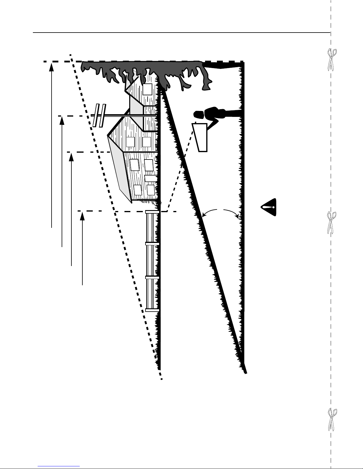
• For your safety, use the slope gauge included as
part of this manual to measure slopes before
operating this unit on a sloped or hilly area. If the
slope is greater than 15° as shown on the slope
gauge, do not operate this unit on that area or
serious injury could result.
Do:
• Mow up and down slopes, not across.
• Remove obstacles such as rocks, limbs, etc.
• Watch for holes, ruts or bumps. Uneven terrain
could overturn the machine. Tall grass can hide
obstacles.
• Use slow speed. Choose a low enough gear so that
you will not have to stop or shift while on the slope.
Always keep machine in gear when going down
slopes to take advantage of engine braking action.
• Follow the manufacturer’s recommendations for
wheel weights or counterweights to improve
stability.
• Use extra care with grass catchers or other
attachments. These can change the stability of the
machine.
• Keep all movement on the slopes slow and gradual.
Do not make sudden changes in speed or direction.
Rapid engagement or braking could cause the front
of the machine to lift and rapidly flip over backwards
which could cause serious injury.
• Avoid starting or stopping on a slope. If tires lose
traction, disengage the blade(s) and proceed slowly
straight down the slope.
•
Do Not:
• Do not turn on slopes unless necessary; then, turn
slowly and gradually downhill, if possible.
• Do not mow near drop-offs, ditches or
embankments. The mower could suddenly turn over
if a wheel is over the edge of a cliff or ditch, or if an
edge caves in.
• Do not mow on wet grass. Reduced traction could
cause sliding.
• Do not try to stabilize the machine by putting your
foot on the ground.
• Do not use grass catcher on steep slopes.
Children
Tragic accidents can occur if the operator is not alert to the
presence of children. Children are often attracted to the
machine and the mowing activity. Never assume that
children will remain where you last saw them.
• Keep children out of the mowing area and in
watchful care of an adult other than the operator.
• Be alert and turn machine off if children enter the
area.
• Before and when backing, look behind and down for
small children.
• Never carry children, even with the blades off. They
may fall off and be seriously injured or interfere with
the safe machine operation.
• Never allow children under 14 years old to operate
the machine. Children 14 years and over should
only operate machine under close parental
supervision and proper instruction.
• Use extra care when approaching blind corners,
shrubs, trees or other objects that may obscure
your vision of a child or other hazard.
• Remove key when machine is unattended to
prevent unauthorized operation.
Service
• Use extreme care in handling gasoline and other
fuels. They are extremely flammable and the vapors
are explosive.
• Use only an approved container.
• Never remove fuel cap or add fuel with the engine
running. Allow engine to cool at least two minutes
before refueling.
• Replace fuel cap securely and wipe off any spilled
fuel before starting the engine as it may cause a fire
or explosion.
• Extinguish all cigarettes, cigars, pipes and other
sources of ignition.
• Never refuel the machine indoors because fuel
vapors will accumulate in the area.
• Never store the fuel container or machine inside
where there is an open flame or spark, such as a
gas hot water heater, space heater or furnace.
• Never run a machine inside a closed area.
• To reduce fire hazard, keep the machine free of
grass, leaves or other debris build-up. Clean up oil
or fuel spillage. Allow machine to cool at least 5
minutes before storing.
• Before cleaning, repairing or inspecting, make
certain the blade and all moving parts have
stopped. Disconnect the spark plug wire, and keep
the wire away from the spark plug to prevent
accidental starting.
• Check the blade and engine mounting bolts at
frequent intervals for proper tightness. Also, visually
inspect blade for damage (e.g., excessive wear,
bent, cracked). Replace with blade which meets
original equipment specifications.
• Keep all nuts, bolts and screws tight to be sure the
equipment is in safe working condition.
• Never tamper with safety devices. Check their
proper operation regularly. Use all guards as
instructed in this manual.
• After striking a foreign object, stop the engine,
remove the wire from the spark plug and thoroughly
inspect the mower for any damage. Repair the
damage before restarting and operating the mower.
• Grass catcher components are subject to wear,
damage and deterioration, which could expose

5
moving parts or allow objects to be thrown. For your
safety protection, frequently check components and
replace with manufacturer’s recommended parts
when necessary.
• Mower blades are sharp and can cut. Wrap the
blade(s) or wear gloves and use extra caution when
servicing blade(s).
• Check brake operation frequently. Adjust and
service as required.
• Muffler, engine and belt guards become hot during
operation and can cause a burn. Allow to cool down
before touching.
• Do not change the engine governor settings or
overspeed the engine. Excessive engine speeds
are dangerous.
• Observe proper disposal laws and regulations.
Improper disposal of fluids and materials can harm
the environment and the ecology.
• Prior to disposal, determine the proper method to
dispose of waste from your local Environmental
Protection Agency. Recycling centers are
established to properly dispose of materials in an
environmentally safe fashion.
• Use proper containers when draining fluids. Do not
use food or beverage containers that may mislead
someone into drinking from them. Properly dispose
of the containers immediately following the draining
of fluids.
• DO NOT pour oil or other fluids into the ground,
down a drain or into a stream, pond, lake or other
body of water. Observe Environmental Protection
Agency regulations when disposing of oil, fuel,
coolant, brake fluid, filters, batteries, tires and other
harmful waste.
Your Responsibility
• Restrict the use of this power machine to persons
who read, understand and follow the warnings and
instructions in this manual and on the machine.

6
SECTION 2: SLOPE GUAGE
15°
SIGHT AND HOLD THIS LEVEL WITH A VERTICAL TREE
A POWER POLE
A CORNER OF A BUILDING
OR A FENCE POST
FOLDONDOTTEDLINE,REPRESENTINGA15°SLOPE
USE THIS PAGE AS A GUIDE TO DETERMINE SLOPES WHERE YOU MAY NOT OPERATE SAFELY.
Do not mow on inclines with a slope in excess of 15 degrees (a rise of approximately 2-1/2 feet every 10 feet). A
riding mower could overturn and cause serious injury. If operating a walk-behind mower on such a slope, it is
extremely difficult to maintain your footing and you could slip, resulting in serious injury.
Operate RIDING mowers up and down slopes, never across the face of slopes.
Operate WALK-BEHIND mowers across the face of slopes, never up and down slopes.
WARNING

7
SECTION 3: ASSEMBLING YOUR LAWN TRACTOR
NOTE: This manual covers various models of
hydrostatic tractors within the 690 series. Please use
instructions pertaining only to your tractor.
Unpacking
•Remove all screws from top of the crate using 1/4"
hex head socket or a flat blade screwdriver.
•To remove ends, grasp top board on the end, and
pull towards you in downward motion. (A hammer
may be helpful). Set panel aside to avoid tire
damage.Repeat procedure on other sides.
•Remove and discard plastic bag which covers unit.
•Loose parts (may include the owner’s guide,
steering wheel, optional oil drain sleeve or hose,
battery fluid, chute deflector, optional mulching
plug, etc.) are on the seat or in a box wrapped in
plastic. Carefully cut and remove the plastic wrap.
Remove the loose parts.
•Make sure that parking brake and hydrostatic
transmission relief valve are released and unit is in
neutral. See page 11-12 for the location of the
parking brake release and the hydrostatic relief
valve.
•Raise the deck and push the unit off the skid.
NOTE: Reference to right or left side of the unit is
observed from the operating position on the driver’s
seat, facing forward.
Tools Required
1. Socket wrench 1/4" or flat blade screwdriver
2. Adjustable or socket wrench 1/2" *
3. Adjustable or socket wrench 9/16"
4. Pair of adjustable or socket wrenches 7/16"
* If your tractor steering wheel cap is square, you must
use a socket wrench to install the steering wheel.
Handling Battery
WARNING: The battery contains sulfuric
acid. This battery acid must be handled
with great care as contact with it can burn
and blister skin. Wear protective clothing
(goggles, rubber gloves and apron) when
working with it.
Keep batteries out of the reach of children.
IMPORTANT:
Should battery acid accidentally splatter
into the eyes or onto the face, rinse the affected area
immediately with clean, cold water. Refer to the
antidotes mentioned below. If there is any further
discomfort, seek prompt medical attention.
Antidote
Use the following antidotes if you come in contact with
the battery acid.
EXTERNAL —Flush with water.
INTERNAL —Drink large quantities of water or milk.
Follow with milk of magnesia, beaten eggs or vegetable
oil. Call physician immediately.
EYES —Flush with cool water for at least 15 minutes,
then get prompt medical attention.
If acid spills on clothing, first dilute it with clean water,
then neutralize with a solution of ammonia/ water or
baking soda/water.
IMPORTANT:
Since battery acid is corrosive, do not pour
it into any sink or drain. Before discarding empty
electrolyte containers, rinse with a neutralizing solution.
WARNING: To avoid sparks, NEVER
connect or disconnect charger clips to
battery while charger is turned on.
Keep all lighted materials (cigarettes,
matches, lighters) away from the battery
as the hydrogen gas generated during
charging can be combustible.
As a further precaution, only charge the
battery in a well-ventilated area. Make
certain venting path of battery drain tube
(if equipped) is always open.
Identifying Battery Type
Figure 1
Type "A"
Type "B"

8
•Compare the battery in your lawn tractor (located
under the seat) with the illustration above. Type “A”
batteries are activated and are ready to use. Type
“B”batteries must be filled with battery fluid (acid)
and charged before they are put into service.
Follow instructions which apply to the battery in
your lawn tractor only.
Activating & Charging Battery
(Type “B”Battery Only)
WARNING: Do not activate battery (i.e. fill
with battery acid) until battery is actually
placed in service. Read warnings about
battery usage in the previous page before
activating the battery.
•Pivot the seat pivot bracket forward. Unhook the
strap which secures the battery (hook is on rear
frame, under the fender). Disconnect the positive
cable from the positive terminal. Save the hardware
for reassembly.
•Remove the battery from the lawn tractor, paying
attention to how the battery is placed in the unit,
and how the drain tube (attached to the battery) is
routed.
•Activate the battery as instructed in the “Quick
Start”brochure included with the battery fluid. Read
instructions carefully.
NOTE: You can continue to assemble the lawn tractor
while the battery is standing for 30 minutes after acid
fill-up, and later while you are charging the battery.
IMPORTANT:
To obtain maximum life from the battery,
charge it prior to initial use.
•Battery P/N 725-1705D: Charge at 2-3 amps for
one hour.
•Battery P/N 725-1707D, 725-0453G, and 725-
1750: Charge at 6 amps for one hour.
•Charge battery after the 30-minute standing period.
NOTE: If you charge the battery at a lower AMP rate,
use a hydrometer to make sure the battery is
completely charged. The hydrometer should read 1.260
minimum at an electrolyte temperature of 60-110oF.
WARNING: Do not charge the tractor
battery at more than 6 amps.
Attaching Steering Wheel
•The hardware for attaching the steering wheel has
been packed inside the steering wheel. Carefully pry
off the steering wheel cap and remove the hardware.
•Remove the steering bellow from the lift lever on
the right side of the tractor.
•Place the steering bellow over the steering shaft
extending through the dash. See Figure 2 .
NOTE: If the openings on each end of the steering
bellow are of two sizes, the smaller end goes down
against the dash of the lawn tractor.
•With the wheels pointing straight, place the steering
wheel over the steering shaft, positioning the
steering wheel as desired.
•Place the washer with the cupped side down over
the steering shaft. Secure with hex lock bolt. See
Figure 2 .
NOTE: If your tractor steering wheel cap is square, you
must use a socket wrench.
•Place the steering wheel cap over the center of the
steering wheel and press it with your hand.
Figure 2
Attaching Seat
NOTE: Your tractor is equipped with one of the
following types of seats. Identify the seat type from the
illustrations below, and follow instructions pertaining to
your tractor.
Manual Adjustment Seat
•Remove the four screws which secure the seat to
the seat pivot bracket. See Figure 3 .Turn the seat
around and place it in position against the seat
pivot bracket, lining up the slotted holes in the pivot
bracket with the holes in the seat. Select desired
position for the seat, and secure with the four
screws removed earlier.
Figure 3
Steering
Wheel Cap
Hex Lock
Bolt
Cupped
Washer
Steering
Bellow
Steering
Shaft
Screws
Seat
Pivot
Bracket

9
NOTE: The seat may have been shipped in a box.
Remove the four screws from the bottom of seat and
place seat in position against the seat pivot bracket.
Follow the directions above to attach the seat.
Quick Adjustment Seat
•Pull out tab on seat stop and hold open while sliding
seat out of seat pivot bracket. See Figure 4 .
Figure 4
•Turn the seat around and line up plastic seat
spacers with the slots in seat pivot bracket. See
Figure 5 .Slide seat in until front seat spacer
engages the seat stop. To adjust the seat, refer to
the adjustment section on page 14.
Figure 5
NOTE: If the seat was shipped in a box, line up plastic
seat spacers with the slots in seat pivot bracket and
slide seat in until front seat spacer engages seat stop.
WARNING: Before operating your unit,
stand behind quick adjustment seat and
pull back on seat, making sure seat is
engaged in seat stop.
Attaching Chute Deflector
The chute deflector must be attached to the right side
of the deck so that it covers the chute opening.
WARNING: Do not operate your unit
unless the chute deflector has been
properly installed.
•Raise the deck to its highest position by pulling the
lift lever all the way back.
NOTE: The mowing deck may be equipped with an
optional mulching plug. Remove the mulching plug by
removing the wing nut on top of the deck. Grasp the
mulching plug and pull out of the deck.
•Remove the hex head cap screws, cupped
washers and hex nuts which are attached to the
deck next to the chute opening.
•Place the chute deflector in position as shown in
Figure 6 . Secure with hardware earlier removed.
Note that the cupped side of washer goes against
the chute deflector.
Figure 6
Installing Mulching Plug
(Optional Equipment)
•Remove the mulching plug from the box packed
with your lawn tractor (if not already removed from
the deck).
•Remove the wing nut from the bolt on the mulching
plug.
•Lift up the chute deflector and insert the mulching
plug through chute opening. See Figure 7 .
Seat
Stop
Tab
Seat Pivot Bracket
Seat
Spacers
Seat
Spacers
Slot
Slot
Seat
Stop
Cupped
Washers
Hex Nuts
Hex Head
Cap Screws

10
•Line up the bolt on the mulching plug with the hole
on top of the deck. Push up on the end of the
mulching plug and secure with the wing nut. See
Figure 7 .
Figure 7
Tire Pressure
•The tires on your unit may be over-inflated for
shipping purposes. Reduce the tire pressure before
operating the unit. Recommended operating tire
pressure is approximately 10 p.s.i. Check sidewall
of tire for maximum p.s.i.
WARNING: Maximum tire pressure under
any circumstances is 30 p.s.i. Equal tire
pressure should be maintained on all tires.
Leveling the Deck
•With unit on hard, level surface, place the blades in
a straight line, and measure the distance from the
outside edge of the blade tips to the ground. If the
distance varies, adjustment is needed.
•Remove the hairpin clip and flat washer from the
bottom of the adjustable lift link on the left side of
the deck. Locate the hairpin clip and the flat washer
on the inside of the lift link.
Figure 8
•Pull the adjustable lift link out of the deck hanger
channel. See Figure 8 . Turn the adjustable lift link
up or down as necessary to level the deck. Usually
only one or two turns are needed.
•Insert the end of the adjustable lift link into the hole
in the deck hanger channel. Recheck the
adjustment. Readjust if necessary.
•When the deck is levelled, secure end of adjustable
lift link with flat washer and hairpin clip.
Installing Battery
Type A Battery
NOTE: If the battery is put into service after the
expiration of the date shown on top of the battery,
charge it for a minimum one hour at 6-10 amps.
•Lift the seat and remove the plastic cover from the
negative terminal.
•Remove the hex bolt and nut from the negative
(black) cable. Attach negative cable to the negative
terminal with this bolt and nut.
Type B Battery
•Lift the seat. Make sure both the negative (black)
cable and the positive (red) cable are routed up
through the battery compartment. See Figure 9 .
Figure 9
•Replace the battery in the battery compartment as
it was before. Make sure that the positive terminal is
toward the front of the unit.
•Attach the positive (red) cable to the positive
terminal of the battery. Secure with hex bolt and nut
previously removed. Slide rubber boot down over
the positive terminal.
•Remove the hex bolt and nut from the negative
(black) cable. Attach negative cable to the negative
terminal with this bolt and nut.
Chute
Deflector
Wing Nut
Mulching
Plug
Hole in
Deck
Chute
Opening
Bolt
Deck Hanger
Channel
Adjustable
Lift Link
Positive Terminal
(Inside Rubber Boot)
Battery
Strap
Negative
Cable Negative
Terminal
Battery
Compartment

11
•Secure battery by hooking battery strap into slot in
rear frame, under the fender. See Figure 10 .
Figure 10
•Insert the drain tube down through the hole in the
battery compartment and the hole in the transaxle
reinforcement bracket located on the right side of
the unit. See Figure 10 . Be certain drain tube is
routed away from the wheel rim.
•Trim excess end of drain tube if necessary (about
4" should extend past the bracket or cable tie).
SECTION 4: KNOW YOUR LAWN TRACTOR
Compare the illustrations in Figure 11 with the controls present on your tractor to familiarize yourself with the
location and features of various controls.
Figure 11
Slot
in Frame
Battery
Strap
Drain
Tube
Transaxle
Reinforcement
Bracket
Hole
Light
Switch
(Optional) Ignition
Switch
Choke
Throttle
Control
Ammeter
(Optional)
Lift
Lever
Clutch-Brake
Pedal
Hydrostatic
Control
Lever
Relief
Valve
Parking
Brake
Knob
Deck
Lift Indicator
(Optional)
Lift Lever

12
Ignition Switch
The ignition switch is located on the dashboard. Start
the engine by turning the key to the START position.
When the engine is running, leave the key in the ON
position. To stop the engine, turn the key to the OFF
position.
WARNING: Remove the key from the
tractor, when the tractor is not in use, to
prevent accidental starting.
Throttle Control
The throttle control is located on the dashboard and is
used to regulate the engine speed. To get maximum
efficiency in cutting grass, the throttle should be in the
FAST position when operating the tractor.
Choke Control
The choke control is located on the dashboard and is
operated manually. Details for the choke operation are
covered in the separate engine manual packed with
your unit.
Hydrostatic Control Lever
The hydrostatic control lever is located on top of the
fender on the right side of the tractor. This single control
lever, connected to the hydrostatic transmission,
controls both the speed and direction of the tractor.
Infinite speed control is achieved by moving the control
lever forward or backward. The farther forward or
backward you move the control lever, the faster you will
travel. Pulling the control lever into neutral (N) area will
stop the tractor.
Clutch-Brake Pedal
The clutch-brake pedal is located on the left side of the
tractor. Depressing the pedal returns the drive unit to
neutral (N) and applies the brake. The clutch-brake
pedal must be depressed to start the engine.
Parking Brake
To set the parking brake, depress the clutch-brake
pedal, pull up the parking brake knob and release the
clutch-brake pedal. It will stay in the raised position. To
release the parking brake, depress and release the
clutch-brake pedal while pushing down on the parking
brake knob. The parking brake must be set if the
operator leaves the seat with the engine running.
Relief Valve
A hydrostatic relief valve is provided so the unit can be
moved without the engine running. The lever which
operates the relief valve is located on the console.
To operate the relief valve, place the hydrostatic control
lever in neutral, release the parking brake, push the
lever forward and to the right to lock. Make sure to
release the lever by pushing it to the left before
operating the engine.
Lift Lever
The lift lever is used to raise and lower the cutting deck
and to engage and disengage the blades. Pulling it all
the way back and locking it disengages the blades.
NOTE: The lift lever must be in the BLADES STOP
position when starting the engine, when shifting into
reverse and if the operator leaves the seat.
Optional Features
NOTE: The controls listed below are optional features
and many tractor models may not be equipped with one
or more of these. Please use information pertinent to
your lawn tractor.
Indicator Lights
If your unit is equipped with indicator lights, two or three
indicator lights are located in the dash panel. If a light
illuminates when attempting to start the unit, proceed
as follows.
CLUTCH: Depress the clutch pedal.
PTO: Place lift lever in the BLADES STOP position.
OIL (Vanguard Twin and Intek Twin Engines Only):
Check the crankcase oil level, and add oil as required.
Deck Lift Indicator
The deck lift indicator (if so equipped) marks the
position being used for the lift lever. Select the lift lever
position desired, press the indicator lever outward,
move it to the position immediately below the lift lever
and release the indicator lever.
Light Switch
The head lamps are operated by pushing the light
switch located on the dashboard. The head lamps will
only operate when the engine is running.
Ammeter
The ammeter registers the rate of battery charge or
discharge. While the engine starts, the ammeter will
register on the discharging side. It should register on
the opposite side (charging) when the engine is running
fast and the battery is not yet completely charged. With
a fully charged battery or with the engine idling, the
ammeter will not show a charge.

13
SECTION 5: OPERATING YOUR LAWN TRACTOR
WARNING: Go up and down slopes, not
across. Avoid sudden turns. Do not
operate the unit where it could slip or tip
over. If the tractor stops while going
uphill, stop the blade(s) and reverse down
the hill slowly.
Do not mow when children or others are
around. Never carry children. Look down
and behind the tractor before and while
backing. Keep the pathway of the tractor
free of obstructions.
Keep safety devices like guards, shields
and switches in place and fully functional.
Make sure that the blade(s) and the engine
have stopped completely before you put
hands or feet near the blade(s).
Gas And Oil Fill-Up
•Check the oil level and add if necessary. Service
the engine with gasoline as instructed in the
separate engine manual packed with your tractor.
Read instructions carefully.
IMPORTANT:
Your tractor is shipped with oil; however
you must check the oil level always before operating.
Be careful not to overfill.
Starting Engine
IMPORTANT:
This unit is equipped with a safety
interlock system for your protection. The purpose of
the safety interlock system is to prevent the engine from
cranking or starting unless the clutch-brake pedal is
depressed and the lift lever is in the BLADES STOP
position. In addition, the lift lever must be in the
BLADES STOP position when the unit is put into
reverse or the engine will shut off. If the operator leaves
the seat with the lift lever engaged and/or without
setting the parking brake, the engine will shut off.
WARNING: Do not operate the tractor if
the interlock system is malfunctioning
because it is a safety device, designed for
protection.
•Place the lift lever in the BLADES STOP position.
•Depress clutch-brake pedal and set parking brake.
•Place the hydrostatic control lever in the NEUTRAL
(N) position.
•Set the throttle control in the FAST position.
•Pull out the choke control (a warm engine may not
require choking).
•Turn the ignition key to the right to the START
position. After the engine starts, release the key. It
will return to the ON position.
NOTE: Protect the starter’s life by using short starting
cycles of several seconds. Cranking more than 15
seconds per minute can damage the starter motor.
•Push choke knob gradually. Move the throttle
control to desired engine speed.
Stopping Engine
•Turn the ignition key to the left to the OFF position.
Remove the key to prevent accidental starting.
IMPORTANT:
If you strike a foreign object, stop the
engine. Remove wire from spark plug, thoroughly
inspect the unit for any damage, and repair the damage
before restarting and operating the mower.
WARNING: Before leaving the operator’s
position, disengage blade(s), place shift
lever in neutral, engage brake lock, shut
off engine and remove key.
Operating Lawn Tractor
•Move throttle control to full throttle to prevent strain
on the engine and to operate the cutting blades.
•Depress the clutch-brake pedal while pushing
down on the parking brake knob so the parking
brake is released, and then release the clutch-
brake pedal.
•Place the hydrostatic control lever in either the
FORWARD or the REVERSE position. The farther
forward you move the lever, the faster you will
travel. Look to the rear before reversing.
•To stop the lawn tractor, pull the hydrostatic control
lever into NEUTRAL (N) or depress the clutch-
brake pedal.
•Be sure that the lawn is clear of stones, sticks, wire,
or other objects which could damage lawn tractor or
engine. For best results and to insure more even
grass distribution, do not mow when the lawn is
excessively wet.
•Before leaving the operator’s position for any
reason, disengage the blades, place the
hydrostatic control lever in neutral, engage the
parking brake, shut engine off and remove the key.
•Follow the same procedure when stopping the unit
to empty a grass bag. This procedure will also
eliminate ‘‘browning’’ of the grass, which is caused
by exposure to hot exhaust gases from engine.

14
Setting Cutting Height
•Select the position for the lift lever which gives the
desired cutting height. Move the deck lift indicator
(if so equipped) so that the lift lever can be returned
to the same position after it is raised.
•Move the deck wheels (if so equipped) to the hole
location so the wheels are 1/4 inch above the
ground. All wheels must be placed in the same
relative position.
Grass Collector
NOTE: Under normal usage bag material is subject to
wear, and should be checked periodically. Be sure to
use only factory authorized replacement bag.
Grass Collector Model OEM-190-063 is available as
optional equipment for lawn tractors with 38" and 42"
decks. Grass Collector Model OEM-190-103 is
available for lawn tractors with 46" decks.
WARNING: The mower should not be
operated without the entire grass catcher
or chute deflector firmly installed in place.
SECTION 6: MAKING ADJUSTMENTS
WARNING: Disconnect spark plug wires
and ground against the engine before
performing any adjustments, repairs or
maintenance.
Manual Adjustment Seat
•To adjust the position of the seat, loosen the four
screws on the bottom of the seat. Slide the seat
forward or backward as desired. Retighten the four
screws. Refer to Figure 3 .
Quick Adjustment Seat
•To adjust the position of the seat, move the seat
adjustment lever (located under the seat) to the left
and slide the seat forward or backwards. See
Figure 12 . Make sure seat is locked into one of the
six positions before operating the lawn tractor.
Figure 12
Hydrostatic Neutral Control
The hydrostatic transmission control is in correct
adjustment when the tractor does not move with the
engine running, the clutch engaged and the hydrostatic
control lever in the neutral position. If adjustment is
necessary, follow these steps:
•Raise both rear wheels off the ground by placing
blocks under the rear frame.
•Remove the transmission panel by removing the
parking brake knob, rubber boot on hydrostatic
relief valve and truss machine screws.
•Loosen the hex jam nut on the speed selector
adjusting rod. See Figure 13 .
•Loosen the hex nut on the scissor mounting
bracket. See Figure 13 .
Figure 13
•Start the engine and run at full throttle.
•Move hydrostatic control lever until you find neutral.
At this position, rear wheels will not rotate in either
direction.
Seat
Adjustment
Lever
Seat
Scissor
Bracket Speed Selector
Adjusting Rod
Scissor
Mounting
Bracket
Hex Jam
Nut
Hex Nut

15
•Depress the clutch-brake pedal until the scissor
brackets come together.
•Shut off the engine.
•Tighten hex nut on the scissor mounting bracket.
•Thread the speed selector rod in or out of the
ferrule until the hydrostatic control lever lines up in
neutral position on the speed control index bracket.
•Tighten hex jam nut against the ferrule.
•Replace the transmission panel, parking brake
knob and rubber boot on relief valve.
•Remove the blocks from under the frame and test
the operation of the tractor.
Deck Leveling
If the tractor is cutting grass unevenly, level the deck
following instructions on page 10.
Cutting Deck Engagement
The cutting deck engagement may be adjusted to
ensure that deck is disengaged when lift lever is in
BLADES STOP position. Correct adjustment as
follows.
•With the engine off, place the lift lever in the highest
cutting position (first position).
•Remove the cotter pin and flat washer which
secure the disengagement rod to the stabilizer
shaft assembly. See Figure 14 .
Figure 14
•Shorten the rod by threading it in, until the ferrule is
against the back of the slot in the lift shaft
assembly, and the rod lines up with the hole in the
stabilizer shaft.
•For more belt tension, the disengagement rod must
be lengthened. To decrease belt tension the
disengagement rod must be shortened.
•Check the adjustment by placing the lift lever in the
BLADES STOP position. The deck should move up
and forward, allowing the belt to become loose.
Start and test for disengagement. Repeat
procedure as necessary.
Brake Adjustment
WARNING: Do not have the engine running
when you adjust the brake.
The brake is located by the right rear wheel inside the
frame. The brake has been set at the factory to the
proper clearance. During normal operation of this
machine, the brakes are subject to wear and will require
periodic examination and adjustment.
Figure 15
•To adjust the brake, adjust the nut so the brake
starts to engage when the brake lever is 1/4" to
5/16" away from the axle housing. See Figure 15 .
Wheel Adjustment
(Units with Adjustable Tie Rod)
The caster (forward slant of the king pin) and the
camber (tilt of the wheels out at the top) require no
adjustment. Automotive steering principles have been
used to determine the caster and camber on the tractor.
The front wheels should toe-in between 1/16- 5/16 inch.
To adjust the toe-in, follow these steps.
•Remove the hex nut and the lock washer, and drop
the end of the tie rod from the axle bracket. See
Figure 16 .
•Loosen the hex jam nut on tie rod.
38" Decks
42" and
46"Decks
StabilizerShaft
Assembly Disengagement Rod
Flat Washer
Hairpin Clip
Stabilizer Shaft
Assembly
Disengagement Rod
Flat Washer
Hairpin Clip
Nut
Brake
Lever
Disc
Brake

16
Figure 16
•Adjust the tie rod assembly for correct toe-in.
Dimension B should be approximately 1/16”-5/16"
less than Dimension A. See Figure 16 inset.
•To increase Dimension ‘‘B,’’ screw tie rod into tie
rod end. To decrease Dimension ‘‘B,’’ unscrew tie
rod from tie rod end. See Figure 16 . Reassemble
tie rod. Check dimensions. Readjust if necessary.
Carburetor
WARNING: If any adjustments are made to
the engine while the engine is running
(e.g. carburetor), disengage all clutches
and blades. Keep clear of all moving parts.
Be careful of heated surfaces and muffler.
Minor carburetor adjustments may be required to
compensate for differences in fuel, temperature,
altitude and load. Refer to separate engine manual for
carburetor adjustment information.
NOTE: A dirty air cleaner will cause an engine to run
rough. Be certain air cleaner is clean and attached to
the carburetor before adjusting carburetor.
SECTION 7: MAINTAINING YOUR LAWN TRACTOR
Battery Care
Type “A” Battery
Type “A”batteries are maintenance-free.
Type “B” Battery
•Check fluid level inside each cell of the battery
every two weeks and before and after charging.
Always keep level between maximum and
minimum fill level.
•Add only distilled water. Never add additional acid
or any other chemicals to the battery after initial
activation.
NOTE: After operating the lawn tractor for a long period
of time, check the fluid level in the battery as it can
overheat and lose fluid.
•The engine is equipped with an alternator which
charges battery when tractor is operated. Under
normal conditions, the battery only needs to be
charged before, during and after off-season
storage.
•To charge the battery:
Battery P/N 725-1705D—Charge at 2-3 amps for
one hour. Battery P/N 725-1707D, 725-0453G, and
725-1750—Charge at 6 amps for one hour.
WARNING: When removing or installing
the battery, follow these instructions to
prevent the screwdriver from shorting
against the frame.
•Removing the Battery: Disconnect negative cable
first, then positive cable.
•Installing the Battery: Connect positive cable first,
then negative cable.
Jump Starting
•First, connect end of one jumper cable to the
positive terminal of the good battery, then the other
end to the positive terminal of the dead battery.
•Connect the other jumper cable to the negative
terminal of the good battery, then to the frame of
the unit with the dead battery.
WARNING: Failure to use this procedure
could cause sparking, and the gas in
either battery could explode.
Cleaning Battery
•Clean the battery by removing it from the unit and
washing with a baking soda and water solution. If
necessary, scrape the battery terminals with a wire
brush to remove deposits. Coat terminals and
exposed wiring with grease or petroleum jelly to
prevent corrosion.
Tie
Rod
Hex Jam
Nut
Tie Rod
End
Axle
Bracket
Hex Nut &
Lock Washer
A
B
1/16"-5/16" Less Than A

17
Battery Failures
Some common causes for battery failure are: incorrect
initial activation, lack of water, adding chemicals other
than water after initial activation, undercharging,
overcharging, corroded connections, freezing. These
failures do not constitute warranty.
Lubrication
WARNING: Always stop engine and
disconnect spark plug wire before
cleaning, lubricating or doing any kind of
work on lawn tractor.
Pivot Points
•Lubricate all pivot points with light oil once a season.
Ball Joints
•The ball joints and drag link ends are permanently
lubricated and do not need periodic lubrication.
Hydrostatic Transmission
The hydrostatic transmission is filled at the factory and
does not require checking. If repairs are needed,
contact your local service dealer. (Hydrostatic
transmission contains approximately 2.5 quarts of SAE
20W50 oil.)
Figure 17
Steering Gears
•Lubricate teeth of steering gears with automotive
multi-purpose grease after every 25 hours of
operation or once a season. See Figure 17 .
Steering Shaft
•Lubricate steering shaft at least once a season with
light oil. See Figure 17 .
Linkage
•Once a season lubricate all the pivot points on the
clutch, brake and lift linkage with SAE 30 engine oil.
See Figure 17 .
Wheels
•The front wheels may be provided with optional
grease fittings. The rear wheels must be removed
from the axle for lubrication. Lubricate at least once
a season with automotive multi-purpose grease.
Cutting Blades
Removing Blade
WARNING: Be sure to disconnect and
ground the spark plug wire(s) and remove
ignition key before working on the cutting
blade to prevent accidental engine
starting. Protect hands by using heavy
gloves or a rag to grasp the cutting blades.
•Remove the hex flange nut which holds the blade to
the blade spindle.See Figure 18.
•Remove the blade from the spindle.
Figure 18
Sharpening Blade
•Remove the cutting blades by following the
directions in the preceding section.
•When sharpening the blades, follow the original
angle of grind as a guide. It is extremely important
that each cutting edge receives an equal amount of
grinding to prevent an unbalanced blade. An
unbalanced blade will cause excessive vibration
when rotating at high speeds, may damage the
tractor and/or could break, causing personal injury.
Balancing Blade
•The blade can be tested for balance by balancing it
on a round shaft screwdriver. Remove metal from
the heavy side until it balances evenly.
Reassembly
•When replacing blades, be sure to install the blade
with the side of the blade marked ‘‘Bottom’’ (or with
Lube
Lube
Lube Blade
Hex Flange
Nut
Deck
Blade

18
part number) facing the ground when the tractor is
in the operating position. Carefully align “star”on
blade with “star”on spindle. Secure with flange nut.
Blade Mounting Torque
Hex Flange Nut: 840 in. lb. min., 1080 in. lb. max.
•All nuts and bolts must be checked periodically for
correct tightness.
Belt Replacement
WARNING: Disconnect the spark plug
wire(s) and ground it against the engine.
Block the wheels of the unit.
NOTE: Figure 19 and Figure 22 are shown with the unit
tipped up for clarity. It is not necessary to tip the unit to
remove the belts. However, for convenience, if you
decide to tip it, remove the battery from the unit first.
•To prevent gasoline leakage, drain the gasoline, or
remove the fuel tank cap. Place a thin piece of
plastic over the neck of the fuel tank and screw on
the cap. Be certain to remove the plastic when
finished changing the belts. Block unit securely.
Deck Belt (38" and 42" Decks)
•Place the lift lever in the engaged (all the way
forward) position.
•Disconnect the spring which is attached to a
bracket on the transaxle, inside the right rear wheel.
Use a spring puller or other suitable tool.
NOTE: When reassembling, make certain belt keeper
pins are assembled in the same locations from which
they were removed. See Figure 19 .
Figure 19
•Place the lift lever in the BLADES STOP position.
•Remove the belt keeper pins from the lower frame.
•Unhook the deck belt from the engine pulley.
•Place the lift lever in the engaged (all the way
forward) position.
•Disconnect the stabilizer plate from the stabilizer
shaft assembly by removing the hairpin clips and
flat washers and sliding out the rod.
•Disconnect the six deck links by removing the
hairpin clips and flat washers.
•Place the lift lever in the BLADES STOP position.
•Slide the deck from beneath the lawn tractor.
•Remove the belt guards at each deck pulley by
removing the self-tapping screws. See Figure 20 .
•Remove and replace the belt, reassemble following
the instructions in reverse order.
Figure 20
Deck Belts (46" Deck)
•Place the lift lever all the way forward.
•Disconnect the spring which is attached to a
bracket on the transaxle inside the right rear wheel.
Use a spring puller or other suitable tool.
NOTE: When reassembling, make certain belt keeper
pins are assembled in the same locations from which
they were removed. See Figure 19 .
•Place the lift lever in the BLADES STOP position.
•Remove the belt keeper pins from the lower frame.
Refer to Figure 19 .
•Unhook the deck belt from the engine pulley.
•Place the lift lever in the engaged (all the way
forward) position.
•Disconnect the stabilizer plate from the stabilizer
shaft assembly by removing the hairpin clips and
the flat washers and sliding out the rod. Refer to
Figure 14 .
•Disconnect the six deck links by removing the
hairpin clips and flat washers.
•Place the lift lever in the BLADES STOP position.
•Slide the deck from beneath the lawn tractor.
•Remove the top deck drive belt by lifting up on the
stabilizer plate, and slipping belt off the pulley.
Engine
Pulley
Belt Keeper Pins
Self-Tapping
Screws
Stabilizer
Plate Belt
Guard
Deck
Pulleys
Belt Guard

19
Figure 21
•Remove the belt cover at the two outside deck
pulleys, by removing the self-tapping screws. See
Figure 21 .
•Release the tension on the spring loaded idler by
pushing the idler toward the rear of the deck.
•Remove the belt from around the idler pulleys, and
remove from the three deck pulleys. See Figure 21 .
•Reassemble new belts, following instructions in
reverse order.
Drive Belt
•Depress the clutch pedal and set the parking brake.
•Remove the deck from the lawn tractor.
•Raise and block the front wheels of the lawn tractor
so you can work under it.
•Remove the transmission panel by removing the
parking brake knob, relief valve rubber boot and
truss machine screws.
•Raise the seat. Disconnect the battery cables.
Remove the battery from the unit.
•Disconnect the idler pulley spring which is attached
to a bracket on the frame, inside the left rear wheel.
Use a spring puller or other suitable tool. See
Figure 22 .
•Remove the three self-tapping screws from the
cooling fan. Remove the fan.
•Remove the center bolt, lock washer and flat
washer, and let the engine pulley drop down so the
belt is past the belt guards. See Figure 22 .
•Roll the belt off of top sheave of engine pulley, onto
the pulley hub.
•Remove the belt from the transmission pulley and
engine pulley, and remove from the unit.
•Reassemble using a new belt, following
instructions in reverse order.
Figure 22
Hydrostatic Transmission Cooling
The hydrostatic transmission is cooled by the oil, fan
and fins. If the hydrostatic transmission runs hot, check
to see if the fan is in operating condition, the oil level is
correct and the fins are clean.
NOTE: DO NOT use high pressure water spray or
steam to clean the hydrostatic transmission.
WARNING: Disconnect spark plug wire
and ground against engine before
performing any adjustments, repairs or
maintenance work on the tractor.
Fuel Filter
•Your unit is equipped with a replaceable in-line fuel
filter. Replace filter whenever contamination or
discoloration is noticed. Order replacement filter
through your authorized engine service dealer.
Cleaning Engine & Deck
•Any fuel or oil spilled on the machine should be
wiped off promptly. Grass, leaves, and other dirt
must not be left to accumulate around the cooling
fins of the engine or on any part of the machine.
•Clean the underside of the deck after each mowing.
Belt Cover
Belt Cover
Self-Tapping Screws
Deck
Pulley
Deck
Pulley
Self-Tapping
Screws
Idler
Pulley
Center Bolt,
Lock Washer &
Flat Washer
Engine
Pulley
Drive
Belt
Idler
Pulley Idler
Pulley
Spring
Bracket
Transmission
Pulley

20
Engine
•Refer to the separate engine manual for engine
maintenance instructions.
•Service air cleaner every 10 hours under normal
conditions. Clean every few hours under extremely
dusty conditions. To service the air cleaner, refer to
the separate engine manual packed with your unit.
•The spark plug(s) should be cleaned and the gap
reset once a season. Spark plug replacement is
recommended at the start of each mowing season;
check engine manual for correct plug type and gap
specifications.
•Maintain engine oil as instructed in the separate
engine manual packed with your unit. Read and
follow instructions carefully.
Oil Drain Sleeve (If equipped)
•Your lawn tractor may have a plastic oil drain
sleeve packed with the loose parts for your
convenience in draining oil from the crankcase. To
drain the oil, snap small end of oil drain sleeve onto
oil sump. See Figure 23 . Remove drain plug and
drain oil into a suitable container.
Figure 23
Oil Drain Valve (If equipped)
•Your lawn tractor may have a valve installed on the
engine for draining oil from the crankcase. See
Figure 24 .To drain the oil, insert the 12" hose
(shipped loose with your unit) over the end of the
valve. Place the other end in a suitable container.
Push in black cap, rotate counter-clockwise and
pull valve open. When oil is completely drained,
push top of valve in and rotate clockwise to close.
Figure 24
Tire Pressure
Recommended operating tire pressure is
approximately 10 p.s.i. Maximum tire pressure under
any circumstance is 30 p.s.i. Equal tire pressure should
be maintained on all tires.
•When installing a tire to the rim, be certain rim is
clean and free of rust. Lubricate both the tire and
rim generously. Never inflate to over 30 p.s.i. to
seat beads.
WARNING: Excessive pressure (over 30
p.s.i.) when seating beads may cause tire/
rim assembly to burst with force sufficient
to cause serious injury.
SECTION 8: OFF-SEASON STORAGE
If the tractor will remain unused for more than 30 days,
prepare it for storage as follows.
•Clean the engine and the entire unit thoroughly.
•Lubricate all pivot and linkage points. Wipe the
tractor with an oiled rag to protect the surfaces.
•Refer to the engine manual for correct engine
storage instructions. The engine must be
completely drained of fuel to prevent gum deposits
from forming on essential carburetor parts, fuel
lines and fuel tanks.
•If your tractor is equipped with the B type battery,
charge it fully. The battery loses some of its charge
each day when the unit is not used. NEVER store
battery without a full charge. Recharge battery
before returning to service or every two months,
whichever occurs first.
•When storing unit for extended periods, disconnect
battery cables. Removing battery from unit is
recommended.
•Store unit in a clean, dry area. Do not store next to
corrosive materials, such as fertilizer.
NOTE: When storing any type of power equipment in
an unventilated or metal storage shed, care should be
taken to rustproof the equipment. Using a light oil or
silicone, coat the equipment, especially any chains,
springs, bearings and cables.
Oil
Sump
Oil Drain
Sleeve
Oil Drain
Valve
12" Drain
Hose
Other manuals for 690 through 699
1
This manual suits for next models
2
Table of contents
Other MTD Lawn Mower manuals
Popular Lawn Mower manuals by other brands

STERWINS
STERWINS PLM1-40Z130.6 Assemby - Use - Maintenance Manual

Jacobsen
Jacobsen Tri King Service manual

Exmark
Exmark FrontRunner Air-Cooled parts manual

Craftsman
Craftsman 917.273421 owner's manual

ENERGREEN
ENERGREEN RoboMAX Use and maintenance instruction manual

Feider Machines
Feider Machines FTDTR4240 owner's manual