MTD PRO MMZ 2554 Operating manual

MMZ 2254, 2554, 2560
25Horsepower
HydrostaticZero-Turn
CommercialRiding
Mower
OPERATOR’S AND SERVICE MANUAL
®
01004029 Rev 99_2.fm Page 1 Monday, September 27, 1999 8:23 AM

2
TABLE OF CONTENTS
Foreword. . . . . . . . . . . . . . . . . . . . . . . . . . . . . . . . . . . . . . . . . . . . . . . . . . . . . . . . 3
Safety Precautions . . . . . . . . . . . . . . . . . . . . . . . . . . . . . . . . . . . . . . . . . . . . . . . . 4
A. General . . . . . . . . . . . . . . . . . . . . . . . . . . . . . . . . . . . . . . . . . . . . . . . . . 4
B. Related to Fuel. . . . . . . . . . . . . . . . . . . . . . . . . . . . . . . . . . . . . . . . . . . . 4
C. When Mowing . . . . . . . . . . . . . . . . . . . . . . . . . . . . . . . . . . . . . . . . . . . . 5
Specifications . . . . . . . . . . . . . . . . . . . . . . . . . . . . . . . . . . . . . . . . . . . . . . . . . . . . 6
Operating Instructions. . . . . . . . . . . . . . . . . . . . . . . . . . . . . . . . . . . . . . . . . . . . . . 7
A. Controls . . . . . . . . . . . . . . . . . . . . . . . . . . . . . . . . . . . . . . . . . . . . . . . .7,8
B. Initial Adjustments . . . . . . . . . . . . . . . . . . . . . . . . . . . . . . . . . . . . . . . . . 9
C. Break-In and Operation . . . . . . . . . . . . . . . . . . . . . . . . . . . . . . . . . . . . 11
Maintenance and Service . . . . . . . . . . . . . . . . . . . . . . . . . . . . . . . . . . . . . . . . . . 13
A. Mower Deck . . . . . . . . . . . . . . . . . . . . . . . . . . . . . . . . . . . . . . . . . . . . 13
B. Hydraulic Oil . . . . . . . . . . . . . . . . . . . . . . . . . . . . . . . . . . . . . . . . . . . . 16
C. Electrical System . . . . . . . . . . . . . . . . . . . . . . . . . . . . . . . . . . . . . . . . 17
D. Tires . . . . . . . . . . . . . . . . . . . . . . . . . . . . . . . . . . . . . . . . . . . . . . . . . . 21
E. Brakes. . . . . . . . . . . . . . . . . . . . . . . . . . . . . . . . . . . . . . . . . . . . . . . . . 22
F.
Hydraulic System . . . . . . . . . . . . . . . . . . . . . . . . . . . . . . . . . . . . . . . . 23
G. Storage . . . . . . . . . . . . . . . . . . . . . . . . . . . . . . . . . . . . . . . . . . . . . . . . 26
Maintenance Schedule . . . . . . . . . . . . . . . . . . . . . . . . . . . . . . . . . . . . . . . . . . . . 27
Wiring Diagram
Warranty
01004029 Rev 99_2.fm Page 2 Monday, September 27, 1999 8:23 AM

3
FORWARD
The MMZ Gasoline Powered Hydraulic Driven Rotary Mowers were developed to
provide superb maneuverability, mid-mount cutting capability for professional land-
scapers, commercial lawn service companies, professional turf managers and golf
course superintendents. The machine incorporates many safety features that
should be studied by all operators and maintenance personnel before use. The list
of safety precautions should receive particular attention.
This manual presents all of the operating and maintenance instructions necessary
to keep your mower at peak efficiency. If properly operated and maintained, your
mower will give dependable service.
CAUTION:
Only thoroughly trained persons should operate
and maintain this mower. This machine can cause
serious injury to anyone who misuses it and does
not understand its operation. For their personal
safety, all operators and maintenance personnel are
required to read this entire manual before operating
the mower.
Hazard control and accident prevention are partially
dependent upon the design and configuration of
the equipment. Notwithstanding, these factors are
also dependent upon the awareness, concern, pru-
dence and proper training of the personnel involved
in the operation, transport, maintenance and stor-
age of the equipment.
01004029 Rev 99_2.fm Page 3 Monday, September 27, 1999 8:23 AM

4
SAFETY PRECAUTIONS
A. General
1. Read this Operator’s Manual before starting the mower. Study the
controls and learn the proper sequence of operation.
2. Do not allow anyone to operate or maintain this machine who has
not read this manual. Never permit children to operate this
machine.
3. Never carry passengers.
4. Do not remove any shields, guards or safety devices. If a shield,
guard or safety device is damaged or does not function, repair or
replace it before operating the mower.
5. Always wear safety glasses and safety shoes when operating or
maintaining this mower. Do not wear loose-fitting clothing.
6. Disconnect the spark plug wires or remove the key from the ignition
to prevent the engine from accidentally starting before performing
any maintenance on this mower.
7. Never run the engine indoors without adequate ventilation.
Exhaust fumes are deadly.
8. To avoid serious burns, do not touch the engine, exhaust pipe or
muffler while the engine is running or until it has cooled after it has
been shut off.
9. The liquid in the battery is dilute sulfuric acid. Always wear safety
glasses and rubber gloves when working on the battery. Do not
overfill the battery.
10. Lead-acid batteries generate hydrogen and oxygen gases which
form an explosive mixture. Keep sparks and flames away at all
times.
11. When looking for oil leaks, never run your hand over hydraulic
hoses, lines or fittings. Never tighten or adjust hydraulic hoses,
lines or fittings while the system is under pressure. If high-pressure
oil penetrates the skin, the oil must be removed within a few hours
by a doctor familiar with this form of injury or serious complications
may result.
B. Related to Fuel
1. Fuel is highly flammable. Please respect it.
2. Do not smoke or permit others to smoke while handling fuel.
3. Always use approved containers for fuel.
4. Always shut off the engine and permit it to cool before removing
the fuel tank cap.
5. Always fill the fuel tank outdoors.
6. If the fuel container spout will not fit inside the fuel tank opening,
use a funnel.
01004029 Rev 99_2.fm Page 4 Monday, September 27, 1999 8:23 AM

5
7. When filling the fuel tank, stop when the fuel reaches one inch from the
top. This space is necessary for tank expansion.
Do not overfill
.
8. Wipe up any spilled fuel.
C. When Mowing
1. Keep adults, children and pets away from the area to be mowed.
2. When operating this mower in the forward direction, DO NOT allow
the steering levers to return to the neutral position on their own.
Always maintain a firm grip on the levers, operate them smoothly
and avoid any sudden movements of the levers when starting or
stopping.
3. If the mower is equipped for side discharge, never use the mower
without the discharge chute installed and placed in the down posi-
tion.
4. Always remove debris and other objects from the area to be
mowed.(
Note
: debris and loose grass will reduce traction.)
5. Mow only in daylight.
6. Watch for holes, sprinkler heads and other hidden hazards.
7. Avoid driving too close to trees, creeks, ditches, sand traps and
other obstacles.
8. Before backing up, check behind you and watch where you’re
going.
9. Always reduce speed when making a turn, and when grass is wet.
10. Always mow up and down slopes, never across the slope. Do not
operate on steep slopes and slow down before turning.
11. Be careful when crossing gravel paths or roadways. Always turn off
the blade clutch switch and wait until the blades stop rotating and
raise the cutting deck to the transport position. Always allow other
vehicles to have the right-of-way.
12. If you hit a solid object while mowing, turn off the blade clutch
switch, place the left and right steering levers in the neutral,
opened-out position, move the throttle to slow, set the parking
brake, shut off the engine and take the key from the ignition switch.
Inspect for damage. Repair any damage. Make sure the blades are
in good condition and that the blade bolts are tight before restarting
the engine.
13. Never leave the mower unattended without: turning off the blade
clutch switch; placing the left and right steering levers in the neutral
opened-out position; moving the throttle to slow; setting the parking
01004029 Rev 99_2.fm Page 5 Monday, September 27, 1999 8:23 AM

6
brake; shutting off the engine and taking the key from the ignition
switch.
14. Never walk or stand on the discharge side of a mower with the
engine running. Turn off the blade clutch switch if another person
approaches while you are operating the mower.
15. Never attempt to operate the traction unit without the mowing deck
attached.
16. Keep the mower and especially the engine and hydraulic compo-
nents clean and free of grease, grass and leaves to reduce the
chance of fire and to permit proper cooling.
SPECIFICATIONS
Engine: 22 HP, 25 HP Kohler
Type: Vertical, Air V-Twin cooled
Air Cleaner: Dual Element
Lube System: Pressurized with oil filter
Starter: 12-volt electric
Traction Drive: Engine to two variable-speed hydraulic pump/motor BDR
units to gearbox on each drive wheel
Hydraulic Tank: 2.0-gallon capacity, One quart filter, and oil cooler
Cutter Deck;Drive: 54", 60", Belt Driven
Clutch: Electric
Deck Lift: Hand lever w/pin lock for height adjustment
Cutting Height: 1-1/2" to 5-1/2"
No. of Blades 3, belt-driven, power take-off from engine
Controls: Engine ignition and start switch; throttle; choke; left and
right steering levers; electric blade clutch switch; parking
brake; mower deck lift
Parking Brake: Internal, mechanical linkage attached to the brake handle
Front Caster Wheels: 13x5 - 6
Tire Pressure: 10 psi Rear, 12 psi front caster
Drive Wheels: w/54"-60" deck, 24x12 - 12
Frame: 2” Steel square tube and plate, all welded construction
Seat: Milsco Adjustable seat with armrests. 5" Adjustment
Fuel Tank: Two 5 gallon w/individual shutoff valves
Ground Speed: 0-8.6 + MPH forward. 0-4.3 MPH reverse
Instrumentation Hour meter, Tachometer, Maintenance-minder
Net Weight: 980 lbs. w/54" deck and 1020 lbs. w/60" deck
01004029 Rev 99_2.fm Page 6 Monday, September 27, 1999 8:23 AM

7
OPERATING INSTRUCTIONS
A. Controls
1.
Engine Ignition and Start Switch:
(See Figure 1.) Located on the
instrument housing below the right side of the operator’s seat.
When the key is inserted and turned clockwise, 45 degrees, the
ignition circuit is closed. Turning the switch further against spring
pressure starts the engine. The engine will only start if the blade
clutch switch is in the “off” position, the parking brake is engaged
and the left and right steering levers are in the neutral, opened-out
position. The key should always be removed from the switch if the
operator leaves the mower’s seat.
2.
Engine Throttle Control:
(See Figure 2.) Located on the left side
of the mower next to the operator’s seat. Moving the throttle control
from the rear to the front will increase the engine speed from slow
to fast.
3.
Left and Right Steering Levers:
(See Figure 3.) These hinged
levers open out to the side in the neutral position to permit the
operator to be seated or to leave the mower’s seat. The operator,
when seated, can pull the levers up to the operating position, a
comfortable forearm’s length away. These levers control all of the
movements of the mower. Pushing both levers forward causes the
mower to move forward. Pulling both levers back causes the
mower to move backward. Pushing one lever ahead of the other
lever causes the traction wheel on the side where the lever is
ahead to rotate faster than the other traction wheel, making the
mower turn toward the side where the lever is behind. When one
lever is pushed forward and the other lever pulled back the same
Figure. 1 Figure. 2
Ignition Switch
Electric Blade
Clutch Tach and Hour Meter
Engine throttle
Choke Lever
01004029 Rev 99_2.fm Page 7 Monday, September 27, 1999 8:23 AM

8
amount, one traction wheel will turn in reverse and the mower will
turn within its own length.
In order to start the engine, both steering levers must be opened
out to the side in the neutral position; the parking brake must be
engaged; and the blade clutch switch must be “off”. However, once
the engine starts, the parking brake must be released before the
operator places the steering levers into the operating position or
the engine will automatically shut off.
Note:The Steering Lever will return toward neutral when released, but they
should be placed in neutral by the driver. If the Drive Handles are not placed in neutral,
the tractor may creep.
4.
Electric Blade Clutch Switch:
(See Figure 1.) Located on the
right side of the mower beside the ignition switch. This is an “on/off”
toggle switch that controls the electric blade clutch which supplies
power to the cutting blades through the PTO. The switch must be
turned off to start the engine and should be turned off for safety
any time another person approaches the mower or the mowing
deck is raised to the transport position. Power to the electric clutch
will also be cut off if the operator leaves the operator’s seat.
5.
Parking Brake:
(See Figure 3.) Located on the left side of the trac-
tion unit. The handle is an overcenter lever which applies the inter-
nal drum-type brake on each drive wheel when the handle is pulled
to the rear. The brake must be engaged in order to start the engine.
6.
Deck Lift Handle:
(See Figure 3.)
Located on the right front corner of
the mowing deck.To raise the mowing
deck to the transport position, the
lever is pulled to the rear and moved
inward to lock into a stop for trans-
port. To lower the mowing deck, raise
Brake
Steering Levers
Deck Lift Handle
Figure. 3
01004029 Rev 99_2.fm Page 8 Monday, September 27, 1999 8:23 AM

9
the deck lift handle and move it outward. This allows the handle to
move forward, lowering the deck to the cutting position.
7.
Fuel Shutoff Valve:
(See Figure 4.)
Located on top of the fuel tank. When
turned in a clockwise direction until it
stops, it will shut off the flow of fuel to
the engine. When turned in a coun-
terclockwise direction it will open and
allow fuel to flow to the engine. Close
this valve if you are not going to run
the mower for a period of 30 minutes
or more to prevent flooding the
engine.
8.
Seat Adjustment Lever:
The Seat
Adjustment Lever is located beneath the seat. The Seat Adjust-
ment Lever is used to move the seat forward and backward. To
place the seat in the desired position pull the seat adjustment lever
to the left then push the seat forward or back to the desired posi-
tion. Release the lever so the seat will lock in place.
9.
Digital Tachometer and Hour Meter:
(See Figure 1) Located on
the right side of the mower in front of the ignition switch. When the
machine is running the tachometer displays engine rpm. When the
machine is off the tachometer displays running time.
10.
Choke Lever:
(See Figure 2) The Choke Lever is located on the
left instrument panel next to the seat. The Choke Lever is operated
manually. Having the Choke Lever in the ON position helps the
engine to start during initial start-up. During normal operation the
Choke Lever should be in the OFF position.
Note:There will be a flashing “LUBE” for each recommended lubrication interval.
There is a flashing “OIL” at each recommended engine oil and filter change.
B. Initial Adjustments
1. Check the fluid levels and tires:
Note:These checks should be made daily, before starting the engine.
a. Fuel: Using a good grade of unleaded, regular gasoline (for
a gasoline engine), fill the fuel tank (beside the engine on
the left or right side of the mower). When the fuel reaches
one inch from the top of the tank, stop. DO NOT OVER-
FILL. Space must be left for expansion.
b. Engine Oil: (Filled at the factory before shipment.) Pull out
the oil dipstick, wipe it off and reinsert it. Pull it out again
and read the oil level. If it is below the operating range, add
Fuel Shutoff Valve
Figure. 4
01004029 Rev 99_2.fm Page 9 Monday, September 27, 1999 8:23 AM

10
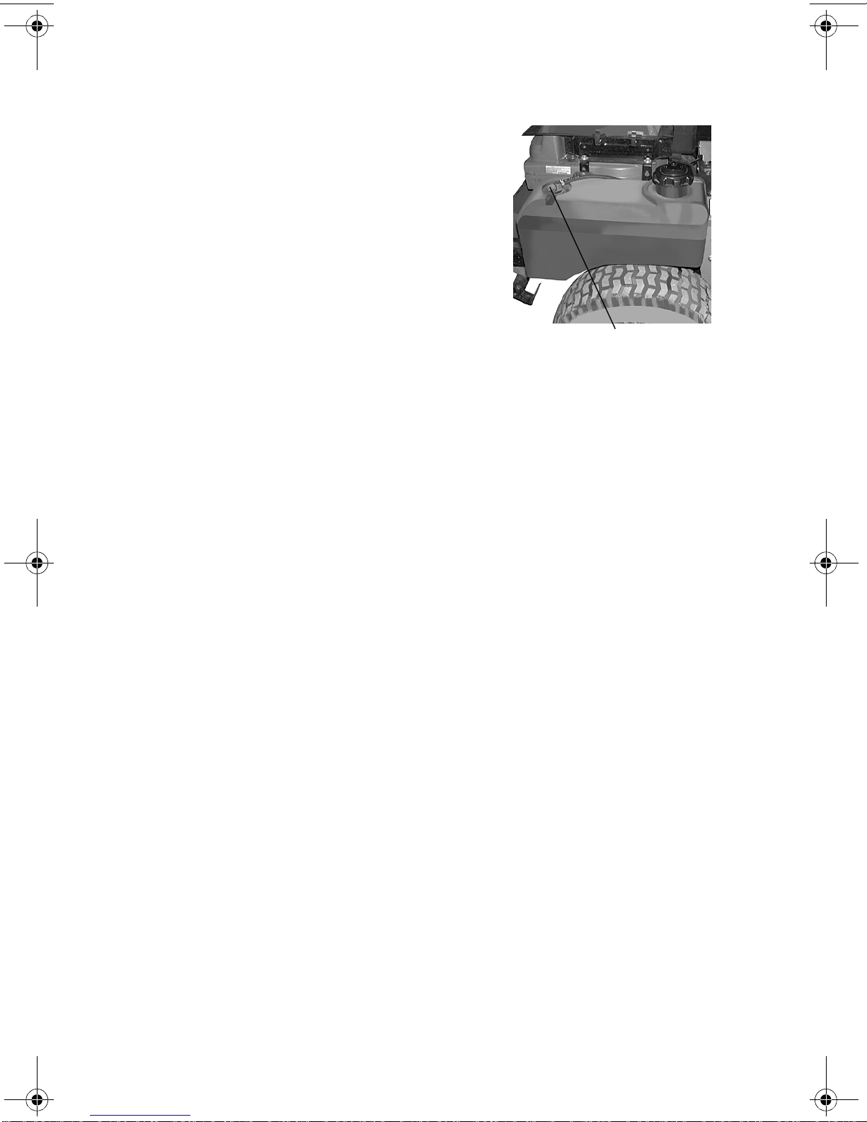
oil through the fill tube using a funnel to bring it up to the
top of the operating range.
Note:Gasoline Engine: Use SAE 10W30 or SAE 10W40 engine oil, rated for ser-
vice SJ.
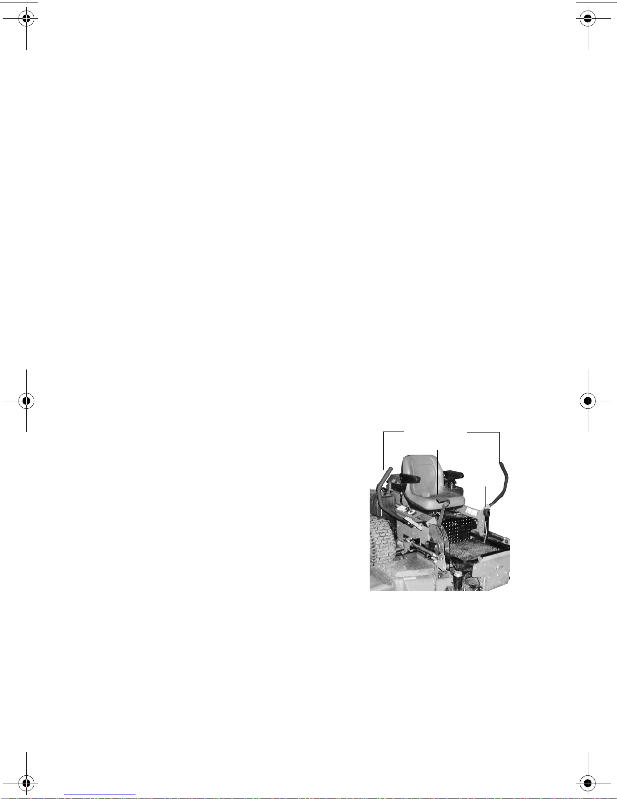
c. Hydraulic Oil: (Filled at the factory before shipment.) The
hydraulic oil tank is located beneath the operator’s seat.
Always wipe off the area around the oil tank fill neck before
checking the oil level to prevent dirt from contaminating the
oil. Remove the cap and make sure the oil level is up to the
lowest hole on the oil tank fill neck. The top hole is for vent-
ing. If the oil level is low, fill with a good grade of SAE20W-
50 oil.
d. Tires: 10 psi Rear, 30 psi Front Caster Tires
Note:New tires are overinflated in order to properly seat the bead to the rim. The
normal working pressure for the traction tires is 8-10 psi. The front caster wheels
should be inflated to 30 psi.
2. Check that all Nuts, Bolts and Screws are Tight.
3. Check the tension of the deck drive belts.
a. Remove the deck cover
b. The tension of the deck drive belts are maintained by a
spring mechanism that adjusts for wear and stretch.
c. Examine the belts for cuts, fraying, and excessive wear.
Replace if any of these are detected.
d. Replace the deck cover.
4.
Adjust the Mowing Deck:
The cutting height is set anywhere in
the range of 1-1/2" to 5-1/2". You may need to adjust the mowing
deck to achieve the proper angle for mowing. Follow the proce-
dures below to set the appropriate angle to the mowing deck.
a. Park the mower on a flat paved surface, engage the parking
brake, shut off the engine, remove the key from the ignition
switch, remove connection of the spark plugs and using the
transport lever, lower the mowing deck into the cutting posi-
tion.
b. Using a ruler, pencil and paper, measure and note the dis-
tance from the paved surface to the bottom edge of the
mowing blade at the front and the back of the deck on each
side of the mower. (Four dimensions.)
Note:The front edge of the mowing deck should be 1/8"-1/4" below the rear edge
of the deck so that the blades are cutting grass in only the front half of their circular
path. This decreases friction and reduces the drive power required.
01004029 Rev 99_2.fm Page 10 Monday, September 27, 1999 8:23 AM

11
c. If the dimension at the front
of the mowing deck is 1/8"-1/
4" lower than the dimension
at the rear of the deck on
each side of the mower, do
not adjust. If not, you will
need to adjust the Deck Lift
Spring Assist (See Figure 5).
You may also need to adjust
the Deck Links (See Figure
5).
d. Lower the mower deck to the
cutting position. With a
wrench loosen the inner rear bolt on the Deck Lift Spring
Assist. To adjust the deck up or down, use a wrench and
with a few turns, adjust clockwise or counter clockwise the
outer rear bolt of the Deck Lift Spring Assist. Repeat this
procedure on the opposite side of the MMZ. Once the deck
is adjusted, retighten bolts.
e. With the deck still in the cutting position, adjust the Deck
Links. With a wrench loosen the top inner bolt of the Deck
Link. To adjust the side of the deck up or down turn the top
bolt clockwise or counter clockwise a few turns. Adjust both
front and rear Deck links as necessary. Retighten bolts.
f. Raise the mowing deck to the transport position using the
transport lever.
g. Use the transport lever to lower the mowing deck to the cut-
ting position and repeat step “b.” above to make sure that
the desired cutting height has been attained. If the dimen-
sions are not correct, repeat steps “c.” through “f.” above.
5. Lubricate all fittings listed in the maintenance section.
C. Break-In And Operation
DANGER:
Reread the “When Mowing” Safety Precautions.
1. Start the Engine:
a. Open the fuel shutoff valve.
b. Sit on the Seat. Set the parking brake “On”.
c. Move the left and right steering levers to the neutral,
opened-out position.
d. Turn the electric blade clutch switch “Off”.
Deck Links
Deck Lift Spring inner bolt
Figure. 5
01004029 Rev 99_2.fm Page 11 Monday, September 27, 1999 8:23 AM

12
e. Push the throttle control to a position a third of the way
between slow and fast.
f. Insert the key in the ignition and start switch and turn the
switch to “On”.
g. Gasoline Engine: If the engine is cold, push the choke to
the on position.
h. Turn the ignition key in a clockwise direction to the “Start”
position until the engine starts.
Note:Do not hold the key in the “Start” position for more than 10 seconds or you
may damage the starter. If the engine does not start in this time, wait about 30 seconds
and try again.
i. Gasoline Engine: Once the engine starts, push the choke
on halfway and as the engine warms, push the choke off all
the way.
2.
Operating the Mower:
Operating a zero-turning-radius mower is
not like operating a tractor-type riding mower. The zero-turning-
radius mower is much more maneuverable and much less fatiguing
to operate. However, getting used to the fingertip control of the
zero-turning-radius mower takes some practice. We strongly rec-
ommend that you locate a “test area” where you can operate the
mower for about 30 minutes without being disturbed.
a. Get into the operator’s seat.
b. Start the engine.
c. Use the transport lever to raise the mowing deck to the
transport position. Make sure the blade clutch switch is off.
d. After the engine has warmed, adjust the throttle to the fast
position.
e. Release the parking brake.
f. Fold in the steering levers to the operating position.
WARNING:
When operating this mower forward, do not allow the steering levers
to return to the neutral position on their own. Always maintain a firm
grip on the steering levers, operate them smoothly and avoid any
sudden movements of the levers when starting or stopping.
g. To go forward, move both steering levers slightly forward
and the mower will slowly move forward. The farther you
move the levers forward the faster the mower will go for-
ward.
h. To back up, move both steering levers slightly backward
and the mower will slowly move backward. The farther you
move the levers backward the faster the mower will go
backward.
01004029 Rev 99_2.fm Page 12 Monday, September 27, 1999 8:23 AM

13
i. To turn, pull the lever back on the side to which you want to
turn. The farther back you pull the lever, the faster and
more sharply you will turn. Initially, you will have to be care-
ful to avoid turning to fast and too far.
j. After you have mastered operating the mower, use the
transport lever to lower the mowing deck to the cutting posi-
tion and pull on the electric blade clutch switch to start the
blades rotating.
k. Practice mowing in straight passes. When you feel confi-
dent, slowly practice mowing around obstacles such as
trees.
3. Parking the Mower:
a. Push off the electric blade clutch switch.
b. Use the Deck Lift Handle to raise the mowing deck to the
transport position.
c. Drive the mower to the cleanup or storage area.
d. Move the throttle to slow.
e. Place the steering levers in the neutral position.
f. Set the parking brake.
g. Turn off the ignition switch and take the key from the switch.
h. Close the fuel shutoff valves.
MAINTENANCE AND SERVICE
WARNING:
Disconnect the spark plug wires or remove the key from the ignition
to prevent the engine from accidentally starting before performing
any maintenance on this mower.
A. Mower Deck
1. Removing the Mower Deck:
a. Apply the parking brake. Remove ignition key and both
spark plug caps.
b. Lower the cutter deck to the ground. Capture the left handle
by placing the height of cut clevis pin above the lift handle.
c. Remove tension of the PTO belt by moving the belt tension-
ing rod.
Note:There is a certain amount of spring tension due to the weight of the deck.
When removing the lift linkage from the deck the tension of the springs will go from the
deck to the lift handle. Not capturing the lift handle while removing the lift linkage from
the deck will cause it to snap back.
d. Detach the engine drive belt.
01004029 Rev 99_2.fm Page 13 Monday, September 27, 1999 8:23 AM

14
e. Remove six linchpins (See Fig. 6) (4) from the deck and (2)
from the front of the mower. Remove the linchpins on the
left and right rear side of the cutter deck (2); remove the
linchpins on the left and right front side of the cutter deck
(2); and remove the linchpins on the front of the mower (2).
f. Turn front caster wheels outward.
g. Shift the deck toward the ignition switch side of the mower
and remove.
h. To install reverse the process.
2. Changing a Blade:
a. Jack up the front of the mowing deck about one foot and
block it in that position.
b. Wrap a rag around one end of the blade and grasp it to pre-
vent it from turning, or secure the blade by placing a block
of wood between the blade and the deck housing.
c. Use a 1-1/8" socket wrench on the pulley side of the spindle
to secure.
d. Remove the hex nut using a 1-1/8" wrench.
e. Remove the hex nut.
f. To replace the blade reverse the above process and tighten
nut to 100-120 lb ft.
Linch Pins
Figure. 6
Height of Cut Clevis Pin Linch Pins
01004029 Rev 99_2.fm Page 14 Monday, September 27, 1999 8:23 AM

15
WARNING:
Never mow with dull blades! Blades that are bent should be
replaced! The cutting blades are sharp and can cause severe injury.
Wrap the cutting surface of the blade with a rag to avoid injury.
a. Set the parking brake.
b. Clean any debris from the blades. Keep blades sharp and
free of build up at all times.
c. Sharpen blades evenly at the original 30° angle to maintain
balanced cutting blades. Do not sharpen the underside of
the blades. Use a electric blade sharpener, a conventional
electric grinder or a hand file to sharpen the blades.
d. Replace any blade with severe nicks or dents that cannot
be removed by filing.
e. Check the balance of the blade after sharpening by placing
it on a blade balancer. Do not use un-balanced blades.
f. If the blade dips on one end, file stock off of the cutting sur-
face on that end.
Note:Blades that cannot be easily balanced—REPLACE.
3. Changing the Blade Drive Belts:
a. Set the parking brake. Remove ignition key and both spark
plug caps.
b. Unscrew the wing nuts from the deck covers and remove
both covers.
c. Using a 1/2" socket breaker bar or socket rachet insert the
male end into the 1/2" opening in the lower idler arm
assembly and pull the idler arm clockwise. While holding
the idler arm back, loosen the blade drive belt from the pul-
ley and slide the belt away from the pulley.
d. Remove tension of the PTO belt by moving the belt tension-
ing rod. Loosen the belt retaining bolt.
e. Pull the tensioner pulley away from the belt and remove the
PTO belt then remove the blade drive belt.
f. Reverse the process to install the belt. Be sure the head of
the bolt is above the top of the idler pulley.
Note:When replacing belts do not overtighten. Adjust the idler pulley so that a
ten-pound pull with a spring scale between two pulleys deflects the belt about 1/2".
01004029 Rev 99_2.fm Page 15 Monday, September 27, 1999 8:23 AM

16
4. Changing the Spindle
Assembly
a. Jack up the front of
the mowing deck
about one foot and
block it in that posi-
tion.
b. Make sure the blade
clutch is disen-
gaged.
c. Remove the deck
cover.
d. Remove the drive
belts. (See 3. Chang-
ing Blade Drive
Belts.)
e. Remove the cutter
blade. (See 2.
Changing a Blade.)
f. Using a wrench or socket rachet remove from the cover
plate all six hex nuts, the three carriage bolts and the three
hex head cap screws. For the 52" and 60" decks there will
be four hex head cap screws and four hex nuts.
d. Remove the spindle assembly.
B.Hydraulic Oil
WARNING:
Never overfill the hydraulic units. Damage can result if the oil level
is not within the operating range.
Note:When adding hydraulic oil, do so in small quantities and recheck the oil
level before adding more. It is important that you do not overfill the reservoir.
1.
Adding Hydraulic Oil
(use SAE20W
50)
a. Place the MMZ on a level
surface and engage the
parking brake.
b. Stop the engine and
remove the key from the
ignition switch.
c. Clean the area around the
Hydraulic Oil fill neck.
Figure. 7
Cover
Plate
Spindle
Hydraulic Tank
Figure. 8
01004029 Rev 99_2.fm Page 16 Monday, September 27, 1999 8:23 AM

17
d. Remove the hydraulic fill cap and check the level. The cor-
rect level is up to the lowest hole of the oil tank fill neck.
e. Pour hydraulic oil into the reservoir up to the lowest hole in
the oil tank fill neck, if necessary.
2. Draining Hydraulic Oil
Used hydraulic oil must be disposed of properly. Do not pour it down a drain or
sewer, or dump it on open land, this creates an environmental hazard. Please be
aware of the environment when disposing of used oil.
a. Place the MMZ on a level surface and engage the parking
brake.
b. Stop the engine and remove the key from the ignition switch.
c. Remove the mower deck. See Mower Deck on page 13.
d. Raise the seat forward to expose the hydraulic oil fill point.
e. Clean the area around the hydraulic fill oil cap.
f. Remove hydraulic fill oil cap.
g. Place a suitable container (at least 2 gallon) under the
hydraulic reservoir and filter.
h. Remove the hydraulic filter to allow hydraulic oil to drain.
i. Place a small pan
under the skid plate
and drain oil from both
left and right axles.
j. Install new hydraulic oil
filter filled with new oil.
k. Add proper amount of
hydraulic oil to reser-
voir.
l. Run and purge gear-
boxes. Check oil level.
m. Add proper amount of
hydraulic oil to reservoir and repeat step L.
C.Electrical Circuit
Danger:
Read General Safety Precautions Nos. 9 and 10.
1.
Battery:
The battery is located beneath the operator’s seat.
Remove the fillcaps and check the level of the liquid electrolyte in
the battery every 50 operating hours. If the level in any of the six
cells has dropped below the bottom of the split ring inside the fill
hole, refill the cell with distilled water. To keep the outside of the
battery clean, brush on a strong solution of bicarbonate of soda
and water and rinse with clean water. Keep the contacts and cable
Figure. 9
Transmission
01004029 Rev 99_2.fm Page 17 Monday, September 27, 1999 8:23 AM

18
ends clean with a wire brush and make sure the connections are
tight. Coat the terminals with petroleum jelly to prevent corrosion.
2.
Battery Storage:
When storing the MMZ for long periods of time
the following guidelines should be taken.
a. Disconnect the battery cables from the terminals and
remove the battery.
b. Clean the battery before storing. A dirty battery will lose its
charge over time.
c. Store the battery with a full charge. A discharged battery
will freeze (refer to the table below).
d. Recharge battery when ever the specific gravity value is
less than 1.225.
3. Battery Removal
Warning:
When removing the cables from the battery follow these steps to avoid a short between
the wrench and the frame.
a. Remove the Negative (black) cable.
b. Remove the Positive (red) cable.
c. Release the hold down straps.
d. Remove the battery without tipping.
4. Installing the Battery
Note:The battery is delivered from the factory fully charged and filled with elec-
trolyte.
a. Attach the Positive (red) cable.
b. Attach the Negative (black) cable.
c. Attach the rubber battery strap.
Specific
Gravity Freezing
Temp (°F)
1.265 -71
1.250 -62
1.200 -16
Specific
Gravity Freezing
Temp (°F)
1.150 5
1.100 16
01004029 Rev 99_2.fm Page 18 Monday, September 27, 1999 8:23 AM

19
5. Jump Starting
Warning:
Failure to use this starting procedure can cause sparking, and the gases in the battery
to explode.
a. Attach the end of the red jumper cable to the Positive termi-
nal (+) of the charged battery.
b. Attach the other end of the red jumper cable to the Positive
terminal (+) of the low charge battery.
c. Attach the end of the black jumper cable to the Negative
terminal of the charged battery.
d. Attach the other end of the black jumper cable to the frame
of the unit with the low charge battery.
6.
Fuses:
There is one fuse located in the wiring between the ignition
and start switch and other electrical components. This is a stan-
dard plug-in type automotive fuse rated at 7.5 amp.
7.
Safety Switches:
There are five safety switches in the electrical
circuit which control the engine. They are (1) the blade clutch
switch, (2) the parking brake switch, (3) the left and (4) the right
steering lever switches and (5) the seat switch.They operate so
that in order to start the engine, the blade clutch switch must be off,
the parking brake must be engaged, and both steering levers must
be opened-out to the side in the neutral position. Once the engine
is started, the seat must be occupied and the parking brake must
be released before either of the steering levers is folded up to the
operating position or the engine’s electronic ignition will be shorted
out and the engine will stop. Also, the seat must be occupied
before the blade clutch switch can cause the blades to rotate.
8.
Safety Switch Operation Checks:
The following operational
checks should be made daily.
a. Blade Clutch Switch: Sit in the operator’s seat. With both
steering levers opened-out in the neutral position and the
parking brake engaged, turn the blade clutch switch “on”
and try to start the engine. The engine should not start. If it
does, the blade clutch switch must be replaced. If the
engine does not start, turn the blade clutch switch “off” and
start the engine. Now turn the blade clutch switch “on” and
the blades should rotate. If the blades do not turn, the blade
clutch switch must be replaced, the seat switch must be
replaced or the electric PTO clutch must be repaired.
b. Parking Brake Switch: Sit in the operator’s seat. With both
steering levers opened-out in the neutral position and the
blade clutch switch “off”, release the parking brake and try
to start the engine. The engine should not start. If it does,
01004029 Rev 99_2.fm Page 19 Monday, September 27, 1999 8:23 AM

20
the parking brake switch must be repositioned or perhaps
replaced. If the engine does not start, engage the parking
brake and start the engine. Swing one steering lever up to
the operating position and the engine should stop. If the
engine does not stop, the parking brake switch must be
repositioned or replaced.
c. Left and Right Steering Lever Switches: Sit in the opera-
tor’s seat. With both steering levers opened-out in the neu-
tral position, the parking brake engaged and the blade
clutch switch “off”, swing the left steering lever up to the
operating position and try to start the engine. The engine
should not start. If it does, the left steering lever switch
must be repositioned or perhaps replaced. Open the left
steering lever to the neutral position and swing the right
steering lever up to the operating position and try to start
the engine. The engine should not start. If it does, the right
steering lever switch must be repositioned or perhaps
replaced. If the engine does not start, Open the right steer-
ing lever to the neutral position and start the engine. Swing
the left steering lever up to the operating position and the
engine should stop. If the engine does not stop, the left
steering lever switch must be repositioned or replaced.
Open the left steering lever out to the neutral position and
start the engine. Swing the right steering lever up to the
operating position and the engine should stop. If the engine
does not stop, the right steering lever switch must be repo-
sitioned or replaced.
d. Seat Switch: With both steering levers opened-out to the
neutral position, the parking brake engaged and the blade
clutch switch in the “off” position, start the engine. Now
release the parking brake, hold down on the back of the
operator’s seat against spring pressure, and swing one of
the steering levers up to the operating position. Release the
operator’s seat and the engine should stop. If the engine
does not stop, the seat switch must be replaced. With both
steering levers folded out in the neutral position, the park-
ing brake engaged and the blade clutch switch in the “off”
position, sit in the operator’s seat and start the engine. Turn
the blade clutch switch to the “on” position and the blades
should start to rotate. Raise up slightly off the operator’s
seat and the blades should stop. If the blades do not stop
when you dismount from the operator’s seat, the seat
switch must be replaced.
e. Electric PTO Clutch: This clutch operates when the
engine is running, the operator is in the operator’s seat and
01004029 Rev 99_2.fm Page 20 Monday, September 27, 1999 8:23 AM
This manual suits for next models
2
Table of contents
Other MTD Lawn Mower manuals
Popular Lawn Mower manuals by other brands

Swisher
Swisher ZT13536, ZT17542B, ZT20050 owner's manual

Makita
Makita DLM533 instruction manual

Lux Tools
Lux Tools E-1800/46-HM 2 Original instructions

Friendly Robotics
Friendly Robotics Robomow RL1000 Operating & safety manual

Craftsman
Craftsman EZ3 917.377540 owner's manual

Agria
Agria 4500 HYDRO operating instructions

Makita
Makita XML06 Series instruction manual

Snapper
Snapper ELT125D331KV SERIES Safety instructions & operator's manual

Cub Cadet
Cub Cadet THE TANK S6031 Operator's manual

Exmark
Exmark Laser Z XP Operator's manual

Craftsman
Craftsman 247.27038 Series Operator's manual

Poulan Pro
Poulan Pro PR17542STC owner's manual