22” Trimmer Mower
3
Fasteners
• The fasteners used on the equipment described in this manual, and the engine that powers it are a combi-
nation of metric and fractional inch. For this reason, wrench sizes are frequently identified in the text, and
measurements are given in U.S. and metric scales.
• If a fastener has a locking feature that has worn, replace the fastener or apply a small amount of releas-
able thread locking compound such as Loctite® 242 (blue).
• Some fasteners, like cotter pins, are single-use items that are not to be reused. Other fasteners, such as:
lock washers, retaining rings, and internal cotter pins (hairpin clips), may be reused if they do not show
signs of wear or damage. This manual leaves that decision to the judgment of the technician.
Assembly instructions
•Torque specifications may be noted in the part of the text that covers assembly. They may be summa-
rized in tables along with special instructions regarding locking or lubrication. Whichever method is more
appropriate will be used. In many cases, both will be used so that the manual is handy as a quick-refer-
ence guide as well as a step-by-step procedure guide that does not require the user to hunt for informa-
tion.
•Lubricant quantity and specification may be noted in the part of the text that covers maintenance, and
again in the section that covers assembly. They may also be summarized in tables along with special
instructions. Whichever method is more appropriate will be used. In many cases, the information will be
found in several places in the manual so that the manual is handy as a quick-reference guide as well as a
step-by-step procedure guide that does not require the user to hunt for information.
• The level of assembly instructions provided will be determined by the complexity of reassembly, and by
the potential for damage or unsafe conditions to arise from mistakes made in assembly.
• Some instructions may refer to other parts of the manual for subsidiary procedures. This avoids repeating
the same procedure two or three times in the manual.
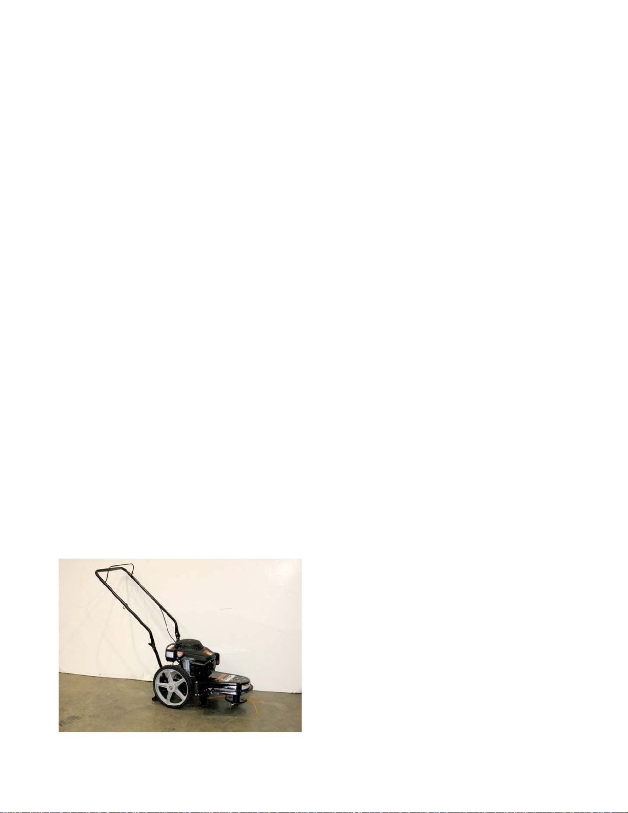
The 22” Trimmer Mower
The 22” wheeled string trimmer was intended for clear-
ing heavy growth from unimproved land. This model has a
engine brake feature. When the engagement control lever
is released, the engine will stop running. See Figure 1.
NOTE: For engine related information refer to publication
769-03354B