EXFO FLS-2600 User manual

-~
ARTISAN
®
~I
TECHNOLOGY
GROUP
Your definitive source
for
quality
pre-owned
equipment.
Artisan Technology
Group
Full-service,
independent
repair
center
with
experienced
engineers
and
technicians
on staff.
We
buy
your
excess,
underutilized,
and
idle
equipment
along
with
credit
for
buybacks
and
trade-ins
.
Custom
engineering
so
your
equipment
works
exactly as
you
specify.
•
Critical
and
expedited
services
•
Leasing
/
Rentals/
Demos
• In
stock/
Ready-to-ship
•
!TAR-certified
secure
asset
solutions
Expert
team
ITrust
guarantee
I
100%
satisfaction
All
tr
ademarks,
br
a
nd
names, a
nd
br
a
nd
s a
pp
earing here
in
are
th
e property of
th
e
ir
r
es
pecti
ve
ow
ner
s.
Find the Exfo FLS-2600 at our website: Click HERE
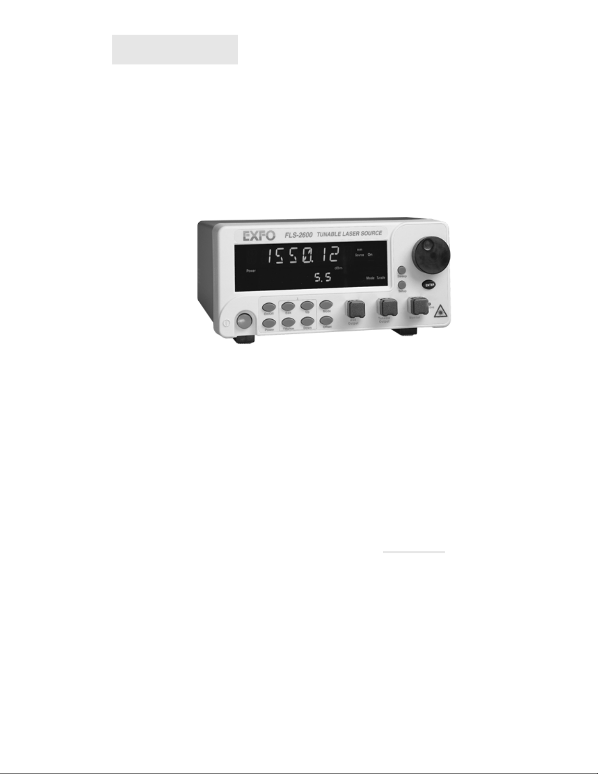
FLS-2600
Tunable Laser Source
If the equipment described herein bears the symbol, the said equipment complies with
the European Community Directive and Standards found in the Declaration of Conformity.
If the equipment described herein bears an FCC statement, the said equipment complies with
the relevant Federal Communications Commission standards.
Instruction Manual
Second Edition
P/N: MAN-141-I .2ACE
Artisan Technology Group - Quality Instrumentation ... Guaranteed | (888) 88-SOURCE | www.artisantg.com

All rights reserved. No part of this publication may be reproduced, stored in
a retrieval system, or transmitted in any form or by any means, be it
electronic, mechanical, photocopying, recording, or otherwise, without the
prior written permission of EXFO Electro-Optical Engineering Inc. (EXFO).
Information provided by EXFO is believed to be accurate and reliable.
However, no responsibility is assumed by EXFO for its use nor for any
infringements of patents or other rights of third parties that may result from
its use. No license is granted by implication or otherwise under any patent
rights of EXFO.
EXFO’s Commerce And Government Entities (CAGE) code under the North
Atlantic Treaty Organization (NATO) is 0L8C3.
The information contained in this manual is subject to change without
notice.
© 2001 EXFO Electro-Optical Engineering Inc.
Words which we consider as trademarks have been identified as such.
However, neither the presence nor absence of such identification affects
the legal status of any trademark.
February 2001
Artisan Technology Group - Quality Instrumentation ... Guaranteed | (888) 88-SOURCE | www.artisantg.com

Contents
Tunable Laser Source iii
Contents
Certification Information.........................................................................................................vi
1 Introduction .................................................................................................. 1
FLS-2600 General Description.................................................................................................. 1
FLS-2600 Main Applications .................................................................................................... 1
FLS-2600 Models and Connector Types ................................................................................... 2
2 Safety Information ....................................................................................... 3
Safety Conventions.................................................................................................................. 3
General Safety Information ..................................................................................................... 3
3 Getting Started ............................................................................................. 7
Hardware Description.............................................................................................................. 7
Turning the FLS-2600 On and Off............................................................................................ 9
Resetting the FLS-2600..........................................................................................................10
Accessing Menus................................................................................................................... 11
4 Using the FLS-2600 Main Menu .................................................................. 13
Setting the Wavelength......................................................................................................... 13
Setting the Output Power ..................................................................................................... 14
Activating/Deactivating the Source........................................................................................ 15
Setting the Source................................................................................................................. 16
Setting the Wavelength Display Unit ..................................................................................... 17
Activating the Wavelength Offset.......................................................................................... 17
5 Using the FLS-2600 Setup Menu ................................................................ 19
Consulting the Shortlist of Wavelengths ............................................................................... 19
Adding a Wavelength to the Shortlist ................................................................................... 19
Deleting a Wavelength from the Shortlist ............................................................................. 21
Setting the Offset Value ........................................................................................................21
Setting the Display Intensity.................................................................................................. 22
Saving a Setup Configuration................................................................................................ 23
Recalling a Setup Configuration ............................................................................................ 24
Displaying the Software Version Number .............................................................................. 25
6 Using the FLS-2600 Sweep Menu ............................................................... 27
Setting the Start Wavelength of the Sweep........................................................................... 27
Setting the End Wavelength of the Sweep ............................................................................ 28
Setting the Number of Sweeps.............................................................................................. 29
Setting the Speed of the Sweep ............................................................................................ 30
Artisan Technology Group - Quality Instrumentation ... Guaranteed | (888) 88-SOURCE | www.artisantg.com

Contents
iv FLS-2600
Starting the Sweep................................................................................................................ 31
Stopping the Sweep..............................................................................................................32
Saving a Sweep Configuration .............................................................................................. 32
Recalling a Sweep Configuration........................................................................................... 34
7 Remote Control ...........................................................................................35
Setting the FLS-2600 for Remote Control.............................................................................. 35
Communication Parameters .................................................................................................. 36
Standard Status Data Structure............................................................................................. 37
Command Structure.............................................................................................................. 40
General Commands—Quick Reference .................................................................................. 41
General Commands............................................................................................................... 42
Specific Commands—Quick Reference .................................................................................. 48
Specific Commands...............................................................................................................51
Error Messages Format.......................................................................................................... 66
SCPI Management Errors (System Errors) .............................................................................. 67
FLS-2600 Error Messages ...................................................................................................... 68
8 Technical Specifications ..............................................................................69
Optical Specifications............................................................................................................ 69
General Specifications ........................................................................................................... 70
9 Maintenance and Troubleshooting ............................................................71
General Maintenance ............................................................................................................ 71
Cleaning Optical Ports........................................................................................................... 71
Fuse Replacement ................................................................................................................. 72
Periodic Source Verification................................................................................................... 73
Software Upgrade................................................................................................................. 73
Recalibration ......................................................................................................................... 75
Transportation and Storage................................................................................................... 75
Contacting the Customer Service Group ............................................................................... 76
10 Warranty ......................................................................................................77
General Information.............................................................................................................. 77
Liability.................................................................................................................................. 78
Exclusions.............................................................................................................................. 78
Certification .......................................................................................................................... 78
Service and Repairs ............................................................................................................... 78
Glossary.............................................................................................................81
Index..................................................................................................................87
Artisan Technology Group - Quality Instrumentation ... Guaranteed | (888) 88-SOURCE | www.artisantg.com

Figures
Tunable Laser Source v
Figures
Figure 2-1. Laser Warning Label ............................................................................................ 4
Figure 3-1. FLS-2600 Front Panel ........................................................................................... 7
Figure 3-2. FLS-2600 Back Panel............................................................................................ 8
Figure 3-3. FLS-2600 Product Nameplate .............................................................................. 9
Figure 3-4. RS-232 Connector Pinout .................................................................................... 9
Figure 3-5. Menu Diagram .................................................................................................. 11
Figure 4-1. Wavelength Mode ............................................................................................. 13
Figure 4-2. Power Mode...................................................................................................... 14
Figure 4-3. Activated Source ............................................................................................... 15
Figure 4-4. ASE Mode.......................................................................................................... 16
Figure 4-5. Wavelength Unit................................................................................................ 17
Figure 4-6. Offset Activated ................................................................................................ 18
Figure 5-1. Default Wavelength Display .............................................................................. 20
Figure 5-2. Offset Value Display .......................................................................................... 21
Figure 5-3. Dimmer Status................................................................................................... 22
Figure 5-4. Current Configuration Number ......................................................................... 23
Figure 5-5. Recalled Configuration ...................................................................................... 24
Figure 5-6. Software Version Number ................................................................................. 25
Figure 6-1. Default Start Wavelength .................................................................................. 27
Figure 6-2. Default End Wavelength.................................................................................... 28
Figure 6-3. Default Number of Repetition ........................................................................... 29
Figure 6-4. Default Speed.................................................................................................... 30
Figure 6-5. Start Display ...................................................................................................... 31
Figure 6-6. Stop Display ...................................................................................................... 32
Figure 6-7. Current Configuration Number ......................................................................... 33
Figure 6-8. Configuration Number ...................................................................................... 34
Figure 7-1. Current Setting.................................................................................................. 35
Figure 7-1. Standard Status Data Structures (IEEE 488.3).................................................... 39
Figure 7-2. Error Message Format ....................................................................................... 66
Figure 9-1. Pulling Out the Fuse Holder............................................................................... 72
Figure 9-2. Replacing the Fuses ........................................................................................... 73
Figure 9-3. Software Upgrade Utility................................................................................... 74
Artisan Technology Group - Quality Instrumentation ... Guaranteed | (888) 88-SOURCE | www.artisantg.com

Certification Information
vi FLS-2600
Certification Information
F.C.C. INFORMATION TO USER
This unit has been tested and found to comply with the limits for a Class B
digital device, pursuant to Part 15 (Subpart B) of the FCC Rules. These
limits are designed to provide reasonable protection against harmful
interference in a residential installation. This unit generates, uses, and can
radiate radio frequency energy and, if not installed and used in accordance
with the instruction manual, may cause harmful interference to radio
communications. However, there is no guarantee that interference will not
occur in a particular installation. If this unit does cause harmful
interference to radio or television reception, which can be determined by
turning the unit off and on, the user is encouraged to try to correct the
interference by one or more of the following measures:
➤Reorient or relocate the receiving antenna.
➤Increase the separation between the unit and receiver.
➤Connect the unit into an outlet on a circuit different from that to which
the receiver is connected.
➤Consult the dealer or an experienced radio/TV technician for help.
WARNING
Changes or modifications not expressly approved by EXFO
Electro-Optical Engineering Inc. could void the user’s authority to
operate the unit.
➤This unit is equipped with a shielded three-wire power cord and plug.
Use this power cord in conjunction with a properly grounded electrical
outlet to avoid electrical shock and to reduce radio frequency
interference that may emanate from the power cord.
Artisan Technology Group - Quality Instrumentation ... Guaranteed | (888) 88-SOURCE | www.artisantg.com

Certification Information
Tunable Laser Source vii
➤Use of shielded remote I/O cables, with properly grounded shields and
metal connectors, is recommended in order to reduce radio frequency
interference that may emanate from these cables.
➤When the GPIB option is present, this unit is equipped with a shielded
GPIB cable.
INDEPENDENT LABORATORY TESTING
This unit has undergone extensive certification testing both
internally, at EXFO, and externally, at an independent, qualified laboratory.
All pre-qualification tests were performed at EXFO while all final tests were
performed at UltraTech Engineering Labs Inc., a renowned test laboratory
from Mississauga, Canada. This guarantees the unerring objectivity and
authoritative compliance of all test results.
INFORMATION TO USER
This unit has been tested and found to comply with the limits for a Class B
digital device. Please see the Declaration of Conformity.
Artisan Technology Group - Quality Instrumentation ... Guaranteed | (888) 88-SOURCE | www.artisantg.com

This page is intentionally left blank.
Artisan Technology Group - Quality Instrumentation ... Guaranteed | (888) 88-SOURCE | www.artisantg.com

Tunable Laser Source 1
1Introduction
FLS-2600 General Description
The FLS-2600 Tunable Laser Source combines a tunable laser with a
broadband source covering the 1520 to 1570 nm range. The FLS-2600 has
been specially designed for testing passive components. Its coherence
length is perfectly suited for detecting parasitic etalon or other interference
effects inside components. This medium coherence also avoids problems
such as connector-induced interference, which is common when using
high-coherence, external cavity lasers. Its ruggedness and immunity to
vibration make it perfect for production testing, product qualification, and
R&D use.
The 60 dB sidemode suppression ratio of the FLS-2600 Tunable Laser
Source provides a better dynamic range than what is possible with a
traditional external cavity laser, thus allowing you to measure crosstalk at
the higher level that is required for passive component testing.
FLS-2600 Main Applications
Main applications include the complete characterization or alignment of
filters, multiplexers, Bragg gratings, and other DWDM components. For
EDFA testing, use the FLS-2600 Tunable Laser Source to check
wavelength-dependent gain, noise contribution, and saturation properties.
It is also very useful for determining the spectral sensitivity of receivers and
detectors.
Furthermore, the FLS-2600 Tunable Laser Source is also equipped to
operate in amplified spontaneous emission mode as a non-coherent
broadband source with a spectrum of non-flattened erbium-doped fiber.
This operation mode is ideal for high-loss tests (isolation, directivity, and
return loss) on passive components.
The FLS-2600 Tunable Laser Source is controlled by supplied software that
offers both manual and programmed specifications of wavelength output
and power level, as well as a range of sweep options. This easy-to-use,
flexible software allows the FLS-2600 Tunable Laser Source to be
combined with a wide variety of other test equipment to perform
automated measurements.
Artisan Technology Group - Quality Instrumentation ... Guaranteed | (888) 88-SOURCE | www.artisantg.com

Introduction
2FLS-2600
FLS-2600 Models and Connector Types
The FLS-2600 Tunable Laser Source can be controlled through standard
GPIB and RS-232 interfaces from any compatible PC or test station.
The FLS-2600 is particularly well suited to the most demanding laboratory
and manufacturing qualification applications.
FLS-2600 Models and Connector Types
Model Connector Type
FLS-2600B-EA-YY EXFO APC Universal Interface
FLS-2600B-EI-YY EXFO UPC Universal Interface
Options YY
89 FC connector adapter
90 ST connector adapter (UPC only)
91 SC connector adapter
95 E-2000 connector adapter
Ta b l e 1 - 1 . FLS-2600 Model and Connector Types
Artisan Technology Group - Quality Instrumentation ... Guaranteed | (888) 88-SOURCE | www.artisantg.com

Tunable Laser Source 3
2 Safety Information
Safety Conventions
You should understand the following conventions before using the product
described in this manual:
WARNING
Refers to a potential personal hazard. It requires a
procedure that, if not correctly followed, may result in
bodily harm or injury. Do not proceed beyond a
WARNING unless you understand and meet the
required conditions.
CAUTION
Refers to a potential product hazard. It requires a
procedure that, if not correctly followed, may result in
component damage. Do not proceed beyond a
CAUTION unless you understand and meet the
required conditions.
IMPORTANT
Refers to any information regarding the operation of
the product that you should not overlook.
General Safety Information
WARNING
Do not install or terminate fibers while a laser source is active. Never
look directly into a live fiber and ensure that your eyes are protected
at all times.
CAUTION
Use of controls, adjustments, and procedures for operation and
maintenance other than those specified herein may result in
hazardous radiation exposure.
Artisan Technology Group - Quality Instrumentation ... Guaranteed | (888) 88-SOURCE | www.artisantg.com

Safety Information
4FLS-2600
General Safety Information
CAUTION
Use of optical instruments with this product will increase eye hazard.
Safety Precautions
While handling optical fibers, laser radiation may be encountered at
source output ports and at fiber ends. Avoid long-term exposure to laser
radiation.
Figure 2-1. Laser Warning Label
The following safety precautions must be observed during the operation
and servicing of the units. Failure to comply with these precautions or with
specific indications elsewhere in this manual violates safety standards of
intended use of the unit. EXFO assumes no liability for the user's failure to
comply with these requirements.
➤This unit is intended for indoor use only.
➤Unit covers can only be opened by an EXFO trained employee.
➤Before powering on the unit, all grounding terminals, extension cords,
and devices connected to it should be connected to a protective
ground via a ground socket. Any interruption of the protective
grounding is a potential shock hazard and may cause personal injury.
➤Whenever the ground protection is impaired, the unit is not to be used
and must be secured against any accidental or unintended operation.
➤Only fuses with the required rated current and specified type (IEC,
250 V, 2 A, fast blow, 0.197 in. x 0.787 in./5 mm x 20 mm) may be used
for replacement. Do not use repaired fuses or short-circuited fuse
holders.
Artisan Technology Group - Quality Instrumentation ... Guaranteed | (888) 88-SOURCE | www.artisantg.com

Safety Information
Tunable Laser Source 5
General Safety Information
➤The unit must be positioned in a way not to block the ventilation holes
located on each side of the unit.
➤Any adjustments, maintenance, and repair of opened units under
voltage should be avoided and carried out only by skilled personnel
aware of the hazards involved. Do not attempt internal service or
adjustment unless another person qualified in first aid is present. Do
not replace any components while power cable is connected.
➤Operation of any electrical instrument around flammable gases or
fumes constitutes a major safety hazard.
➤Installation of replacement parts or modification of the unit should be
carried out by authorized personnel only.
➤Capacitors inside the unit may be charged even if the unit has been
disconnected from its electrical supply.
AC Requirements
The FLS-2600 can operate from any single-phase AC power source
between 100 and 240 V (50/60 Hz). The maximum input current is 2 A.
Power Cable
The FLS-2600 uses an international safety standard three-wire power cable.
This cable serves as a ground when connected to an appropriate AC power
receptacle. The type of power cable supplied with each unit is determined
according to the country of destination.
Only qualified electricians should connect a new plug if needed. The color
coding used in the electric cable depends on the cable. New plugs should
meet the local safety requirements and include the following features:
➤adequate load-carrying capacity
➤ground connection
➤cable clamp
Artisan Technology Group - Quality Instrumentation ... Guaranteed | (888) 88-SOURCE | www.artisantg.com

Safety Information
6FLS-2600
General Safety Information
WARNING
To avoid electrical shock, do not operate the unit if there are signs of
damage to any part of the outer surface (covers, panels, etc.).
To avoid serious injury, the following precautions must be observed
before powering on the unit.
➤If the unit is to be powered via an auto-transformer for voltage
reduction, the common terminal must be connected to the grounded
power source pole.
➤Insert the plug into a power outlet with a protective ground contact. Do
not use an extension cord without a protective conductor.
➤Before powering on the unit, the protective ground terminal of the unit
must be connected to a protective conductor using the unit power
cord.
➤Do not tamper with the protective ground terminal.
Artisan Technology Group - Quality Instrumentation ... Guaranteed | (888) 88-SOURCE | www.artisantg.com
Tunable Laser Source 7
3 Getting Started
This section presents a description of the hardware, provides information
on how to turn the FLS-2600 on and off, and describes the software main
menu.
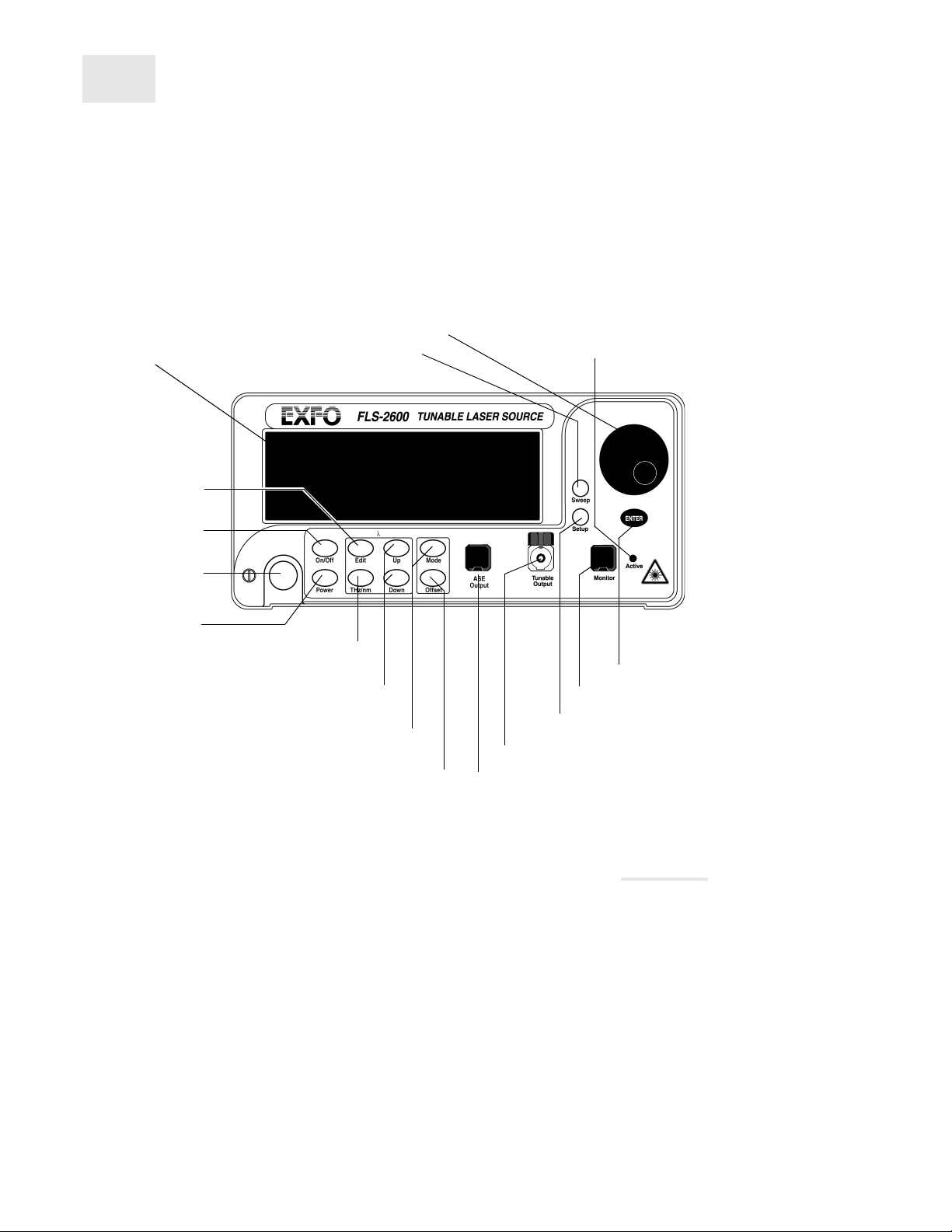
Hardware Description
Front Panel
Figure 3-1. FLS-2600 Front Panel
Note: Your FLS-2600 may slightly differ from the above illustration.
Source
control
Setup menu access
Shortlist controls
Offset control
Power
control
Sweep menu access
Confirmation button
Source mode control
(tunable/ASE)
Display unit control
Wavelength
control
Variable speed selection
knob for menu navigation
and parameter setting
Display
On/off
button
ASE output port (cap closed)
Tunable output port (cap opened)
Monitor port
LED indicating that the
tunable output is on
Artisan Technology Group - Quality Instrumentation ... Guaranteed | (888) 88-SOURCE | www.artisantg.com

Getting Started
8FLS-2600
Hardware Description
Back Panel
Figure 3-2. FLS-2600 Back Panel
Note: Your FLS-2600 may slightly differ from the above illustration.
Product Nameplate
The product nameplate, shown in Figure 3-3, provides the following
information:
➤the part number (P/N) identifying configuration and connector type
➤the serial number (S/N)
➤the product version (Ver.)
➤the date of manufacturing (Mfg. date)
GPIB port Serial port
(RS-232 DTE)
Fuse holder
Power inlet
2
Ground
FLS-2600-E
12345-2P
A-1.0
November 1998
Artisan Technology Group - Quality Instrumentation ... Guaranteed | (888) 88-SOURCE | www.artisantg.com

Getting Started
Tunable Laser Source 9
Turning the FLS-2600 On and Off
Figure 3-3. FLS-2600 Product Nameplate
RS-232 Connector Pinout
The RS-232 connector (serial port) at the back of the FLS-2600 uses a DTE
pinout configuration.
Figure 3-4. RS-232 Connector Pinout
Turning the FLS-2600 On and Off
IMPORTANT
Before turning on the FLS-2600, please read the General Safety
Information on page 3.
To turn the FLS-2600 on and off, press the red button in the lower left-hand
corner of the front panel.
Pin Description Direction
2Receive(Rc) Input
3 Transmit (Tx) Output
5 Signal ground (Gnd) —
Ta b l e 3 - 1 . RS-232 Connector Pinout Configuration
Part number
Serial number
Version number
Manufacturing date
FLS-2600-E
12345-AB
A-1.0
November 1998
P/N
S/N
Ver.
Mfg.
date
1234 5
6789
Artisan Technology Group - Quality Instrumentation ... Guaranteed | (888) 88-SOURCE | www.artisantg.com

Getting Started
10 FLS-2600
Resetting the FLS-2600
Upon startup, the unit beeps twice, performs a self-test, and then enters the
main menu (in tunable mode) with the same settings that were active
when the unit was last turned off, with the source deactivated.
When the unit is turned off, the following items remain in non-volatile
memory:
➤current power setting
➤current wavelength setting
➤current source (tunable/ASE)
➤current display mode (wavelength/power)
➤current wavelength display unit (nm/THz)
➤shortlisted wavelengths (up to 400)
➤offset setting (up to 5)
➤remote control settings
➤saved configurations (up to 10)
Note: The power cord is the most effective disconnecting device. To ensure the
power is completely turned off, disconnect the power cord.
Certain internal mechanisms can sometimes take a few seconds to adjust,
depending on the operation. If the FLS-2600 is performing internal
adjustments (for example after having changed the wavelength or the
source mode), no buttons should be pressed while data flashes on
the display.
Resetting the FLS-2600
While turning on the unit, press ENTER until the unit beeps repeatedly.
All the user-defined parameters are reset to their default values.
Artisan Technology Group - Quality Instrumentation ... Guaranteed | (888) 88-SOURCE | www.artisantg.com

Getting Started
Tunable Laser Source 11
Accessing Menus
Accessing Menus
The blue buttons to the right of the display give access to single-level
menus: Sweep and Setup. Access to these menus is possible in any
situation of the main menu in tunable operation, even while the source is
active. The following diagram shows these two menus and their items.
Figure 3-5. Menu Diagram
To move between menu items, rotate the selection knob.
To exit a menu, press the button that gave access to the menu (the
FLS-2600 will return to the state in which it was prior to entering the
menu).
It is not possible to toggle between the Sweep and Setup menus without
first exiting the active menu.
Note: The unit will beep whenever the FLS-2600 does not allow an operation.
Setup
LM-START
Sweep
LM-STOP REPEAT START STOP SAVE
SPEED
LAMBDA OFFSET DIMMER SAVE RECALL
GPIB-RS VERSION
RECALL
Artisan Technology Group - Quality Instrumentation ... Guaranteed | (888) 88-SOURCE | www.artisantg.com
Table of contents
Other EXFO Recording Equipment manuals


