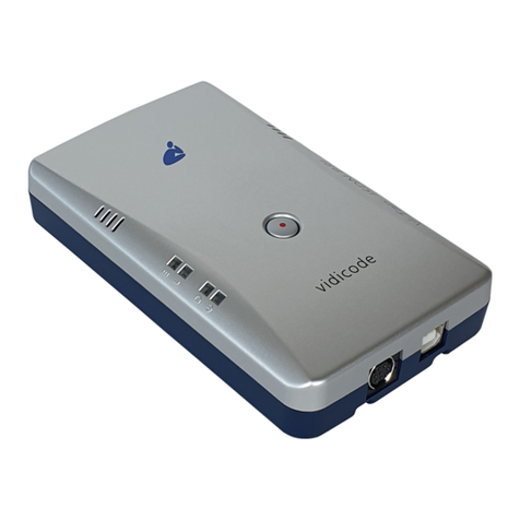
Strand Lighting 63035 Original operating instructions

0
-
-
-

Strand Lighting Offices
The material in this manual is for information purposes only and is subject to change without notice.
Philips Strand Lighting assumes no responsibility for any errors or omissions which may appear in this
manual. For comments and suggestions regarding corrections and/or updates to this manual, please
contact your nearest Philips Strand Lighting office.
El contenido de este manual es solamente para información y está sujeto a cambios sin previo aviso.
Philips Strand Lighting no asume responsabilidad por errores o omisiones que puedan aparecer. Cualquier
comentario, sugerencia o corrección con respecto a este manual, favor de dirijirlo a la oficina de Philips
Strand Lighting más cercana.
Der Inhalt dieses Handbuches ist nur für Informationszwecke gedacht, Aenderungen sind vorbehalten.
Philips Strand Lighting uebernimmt keine Verantwortung für Fehler oder Irrtuemer, die in diesem
Handbuch auftreten. Für Bemerkungen und Verbesserungsvorschlaege oder Vorschlaege in Bezug auf
Korrekturen und/oder Aktualisierungen in diesem Handbuch, moechten wir Sie bitten, Kontakt mit der
naechsten Philips Strand Lighting-Niederlassung aufzunehmen.
Le matériel décrit dans ce manuel est pour information seulement et est sujet à changements sans préavis.
La compagnie Philips Strand Lighting n'assume aucune responsibilité sur toute erreur ou ommission
inscrite dans ce manuel. Pour tous commentaires ou suggestions concernant des corrections et/ou les
mises à jour de ce manuel, veuillez s'll vous plait contacter le bureau de Philips Strand Lighting le plus
proche.
Information contained in this document may not be duplicated in full or in part by any person without
prior written approval of Philips Strand Lighting Inc. Its sole purpose is to provide the user with
conceptual information on the equipment mentioned. The use of this document for all other purposes is
specifically prohibited.
Document Number: 2-450200-020
Version as of: 04 April 2012
Vision.net RS232 Serial Interface Port Installation & Operation Guide
Strand Lighting - Dallas 10911 Petal
Street
Dallas, TX 75238
Tel: 214-647-7880
Fax: 214-647-8030
Strand Lighting - New York 267 5th
Ave, 4th Floor
New York, NY 10016
Tel: 212-213-8219
Fax: 212-532-2593
Strand Lighting - Asia Limited Unit
C, 14/F, Roxy Industrial Centre No.
41-49 Kwai Cheong Road
Kwai Chung, N.T., Hong Kong
Tel: +852 2796 9786
Fax: +852 2798 6545
Strand Lighting - Auckland
19-21 Kawana Street
Northcote, Auckland 0627
New Zealand
Tel: +64 9 481 0100
Fax: +64 9 481 0101
Strand Lighting - Europe
Marssteden 152
Enschede 7547 TD
The Netherlands
Tel: +31 53 4500424
Fax: +31 53 4500425
Website:
www.strandlighting.com

Vision.net RS232 Interface Port Installation & Operation Guide
1
Important Safeguards
TABLE OF CONTENTS
Overview ...................................................................................................................................2
Vision.net System Overview............................................................................................. 2
Vision.net RS232 Serial Interface Port Overview ............................................................ 2
Installation .................................................................................................................................3
Installation Steps............................................................................................................... 3
Operation ...................................................................................................................................4
Communication Modes..................................................................................................... 4
ASCII Codes For Vision.net Show Control Protocol ....................................................... 4
Specifications ............................................................................................................................5
When using electrical equipment, basic safety precautions should always be followed
including the following:
a. READ AND FOLLOW ALL SAFETY INSTRUCTIONS.
b. Do not use outdoors.
c. Do not mount near gas or electric heaters.
d. Equipment should be mounted in locations and at heights where it will not
readily be subjected to tampering by unauthorized personnel.
e. The use of accessory equipment not recommended by the manufacturer
may cause an unsafe condition.
f. Do not use this equipment for other than intended use.
g. Refer service to qualified personnel.
SAVE THESE INSTRUCTIONS.
WARNING: You must have access to a main circuit breaker or other power
disconnect device before installing any wiring. Be sure that power is disconnected
by removing fuses or turning the main circuit breaker off before installation.
Installing the device with power on may expose you to dangerous voltage and
damage the device. A qualified electrician must perform this installation.
WARNING: Refer to National Electrical Code® and local codes for cable
specifications. Failure to use proper cable can result in damage to equipment or
danger to persons.
CAUTION: Wire openings MUST have fittings or lining to protect wires/cables
from damage. Use 90° C copper wire only!

Installation & Operation Guide Vision.net RS232 Interface Port
2
OVERVIEW
Vision.net System Overview
The Vision.net System is designed to control architectural lighting by distributing both power
and intelligence. The system provides processing power and control at each respective Push
button, Fader or Touch Screen Station, eliminating the need for a central processor. Fader Sta-
tions provide individual control for up to 15 channels, 8 scenes plus "Off," all with adjustable
fade times. By combining Vision.net Fader Stations, Vision.net Preset Stations and Vision.net
Touch Screens, the system provides remote access to scenes, Master Raise/Lower control,
Multi-room partition control, or Master Station Lockout.
Vision.net Stations are compatible with Strand Lighting A21, R21, C21 and EC21
Dimming Cabinets.
Vision.net products are controlled by the Vision.net System protocol. All Vision.net control
devices must be connected to the Vision.net system and given a unique ID (or address) in
order to interact properly. The ID identifies the device on the network and allows the device to
avoid network collisions when transmitting data.
Vision.net RS232 Serial Interface Port Overview
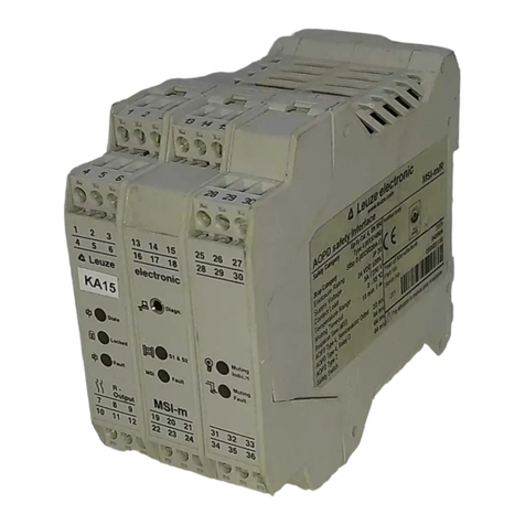
The Vision.net RS232 Serial Interface Port (Strand Part No: 63035) allows integration with the
Vision.net Network using standard RS232 communication. The RS232 Interface has the abil-
ity to receive and transmit data in two modes: Vision.net Protocol (binary) and Show Control
Protocol (standard ASCII). The unit will sense the incoming protocol and automatically
switch to the proper mode.
The RS232 Interface Port
accepts standard 9-pin
RS232 serial cable connec-
tions of up to 25 feet.
Note:
When sending/receiving
Vision.net commands, the
PC requires the use of
Vision.net Desktop soft-
ware. The Vision.net Desk-
top software (67518) is sold
separately and is available
through your authorized
dealer.
Receive Indicator - Green
LED indicates valid data
received when lit.
Transmit Indicator - Red
LED indicates valid data
transmit activity when lit.
RS232 Connector -
Standard RS232 serial
port connector for
input of ASCII or
Vision.net protocol.

Vision.net RS232 Interface Port Installation & Operation Guide
3
INSTALLATION
The Vision.net Network consists of a single CAT5e cable connecting all modules in a daisy
chain manner. All units connect to the network using a 9-pin plug-in connector (included).
Installation Steps
Step 1. Unpack unit and inspect for any signs of shipping damage. Ensure that two
mounting screws are included.
Step 2. Connect Vision.net Network Cable to 9-pin connector at back of RS232 Interface
Port.
Step 3. Insert RS232 Interface Port into standard deep rough-in box (not included). Secure
with two supplied mounting screws.
Step 4. Snap faceplate into place.
A standard Windows-compatible computer can be connected to the Vision.net Network using
the RS232 Interface Port. The port accepts a standard one-to-one 9-pin serial cable up to 25
feet in length.
RS232 Interface Port PC Computer
Pin 1 (NU) Pin 1 (NU)
Pin 2 (TX) Pin 2 (RD)
Pin 3 (RX) Pin 3 (TD)
Pin 4 (NU) Pin 4 (NU)
Pin 5 (GND) Pin 5 (GND)
Pin 6 (NU) Pin 6 (NU)
Pin 7 (CTS) Pin 7 (RTS)
Pin 8 (RTS) Pin 8 (CTS)
Pin 9 (NU) Pin 9 (NU)
9-Pin
RS232
Faceplate
Connector
Interface
Rough-In Box
(not included)
Pin Signal
1 WH/OR (+ Data)
2OR(-Data)
3SHIELD
4 WH/GN (+ Volts)
5 GN (Ground)
6WH/BL(+Volts)
7 BL (Ground)
8 WH/BR (+ Volts)
9 BR (Ground)
9-Pin Connector Wiring

Installation & Operation Guide Vision.net RS232 Interface Port
4
OPERATION
Communication Modes
The Vision.net RS232 Serial Interface Port operates in one of two modes: Vision.net (binary)
or Show Control (ASCII).
The unit will sense the incoming protocol and automatically switch to the proper mode. Note
that it may take several messages from either the third-party system or the Vision.net Designer
PC before the RS232 Interface switches modes.
ASCII Codes For Vision.net Show Control Protocol
* Sending a second <cr> after a RA or LW command will automatically send the proper ST command
Vision.net Mode Show Control Mode
8 Bit 8 Bit
1 Stop Bit 1 Stop Bit
19200 Baud 9600 Baud
Protocol: Binary Protocol: ASCII
Vision.net
Command RS232
Protocol Vision.net
Command RS232
Protocol
Start Preset
Toggle Down
Toggle Up
Learn Preset
Slider Level
Learn Submaster
Manual
Expander Group
Start Raise
Start Lower
Stop Raise/Lower
SP rrr pp tt<cr>
TD rrr ccc<cr>
TU rrr ccc<cr>
LP rrr pp<cr>
SL rrr ccc lll<cr>
LS rrr ss<cr>
MN rrr ggg lll … lll<cr>
EG rrr ee<cr>
EG rrr ee ff lll … lll<cr>
RA rrr qqq<cr>
LW rrr qqq<cr>
ST rrr qqq<cr> *
Record Blind
Lock Button
Unlock Button
Smart On
Smart Off
Define Room Link
Submaster Level
Take Control (sub)
Set Channel
Set Mode
Send Mimic
Console Button
Console LED
RB rrr pp ggg lll … lll<cr>
LB idd n<cr>
UB idd n<cr>
SN idd n<cr>
SF idd n<cr>
DR x fff rrr … rrr<cr>
SB rrr ss lll<cr>
TC rrr ggg lll … lll<cr>
SC rrr ccc lll rr<cr>
SM mm<cr>
MC idd n a<cr>
CB idd n a<cr>
CL idd n a<cr>

Vision.net RS232 Interface Port Installation & Operation Guide
5
where:
rrr Room (1 - 255) qqq Coded Channel
pp Preset (1 - 32) [0 = off] (0: Reserved
tt Rate Index 1 - 127: Channels 1 to 127
ccc Channel ( 1-127) 128: All Channels in room
lll Level (0 - 255) 129 - 255: Channel in Preset: 1 - 126
ss Submaster Index (1 - 16) 255 current preset channels)
ggg Grand Master Level (0 - 255) x 0 = Clear All Links, 1 = Do not clear
ee Expander Group (0 - 15) mm Mode (0 = All modes)
ff Index of First Channel (1 - 127) fff First Room (1-255)
n Button/LED (1-255)
a Action (0/1= Off/On or Button Up/Down for Send Mimic Command)
(0/1= Button Down/Up for Console Button Command)
(0/1= LED Off/On for Console Button Command)
SPECIFICATIONS
Electrical:
• Input Power: +18-26 VDC (powered from Vision.net network)
• Current: 20mA
• Temperature
- Storage: -25° to 85° C
- Operating: 0° to 40° C
- Relative Humidity: 30-90% (non-condensing)
Communications:
• Vision.net Protocol (binary)
•ASCII
Mechanical:
Backbox
(by others)

Part No. 2-450200-020
Table of contents
